Note: Descriptions are shown in the official language in which they were submitted.
.
. .~.., ~ . .
.,....`
Fle~lble eannula
The invention relates to a flexible cannula (trocar sleeve) ~ - ;
according to the preamble of claim 1 and the preamble of claim
2.
. .. .. , . ~ .
Conventional rigid cannulae with the features of the preamble of
claims 1 and 2 which are used in endoscopic operations consist
of a tube, whose distal zone is introducible into the inside of
the body through a trocar puncture point, and a top piece which
is attached to the proximal end of the tube. At its proximal
end face the top piece has an opening, essentially aligned with
the cross-section surface of the tube, to which is allocated a
seal engaging at the shaft of introduced operation instruments.
Located in the inside of the top piece is a closure device for
the separate closing of the opening. Additional equipment, for
example a trocar with the help of which the puncture point is
produced in the body wall and which is withdrawn from the
cannula following the in~ertion of the cannula into the body
wall, or a reduction cap with seal for the use of instruments
whose external diameter is much smaller than the internal
dlameter of the cannula, can be secured on the prox~mal end face
of the top piece with the help of coupling elements. In the case
of operatlons in the abdominal area in particular, a gas, e.g.
carbon dioxide, i8 introduced into the inside of the body at
overpressure in order that the organs detach from the body wall,
which greatly facilitates the operation. A gas connection with
': ' :
". . , ~..'~.', ~;
2 -
a valve can be provided at the top piece of the cannula for this
purpose.
If no operation instrument is introduced into the cannula, the
closure device is closed in the inside of the top piece, so that
the compressed gas cannot escape. Upon insertion of an operation
instrument, the afore-mentioned seal engages at its shaft so
that an escape of gas is prevented although the closure device
mu-~t now be opened.
A disadvantage with the previously known cannula is that it does
not permit the introduction of bent operation instruments. At
best, very thin and only slightly bent instruments could be
inserted into a large-diameter cannula. Attempts are thus being
made to develop instruments having ~oints or hinges which are
straight when guided through the cannula and whose distal zone
is then bent in the inside of the body. Instruments with hinges
are of a very costly design, however; for example, they require
internal actuation systems in order to allow movement in the
distal zone. Such instruments consequently have a larger shaft
diameter and can thus be introduced only through large cannulae
which are generally less advantageous for the patient than
small-diameter cannulae. Their elaborate design also makes them
more expensive to produce.
Cannulae with a flexible tube are known for operations in the
thorax region. Upon entry of air into the inside of the thorax,
the wings of the lung change their shape and the organs are
readily accessible for the operation; hence no compressed gas i~
required for such operations. There is thus no need for a
sep~rate closure device in the top piece of the cannula, 80 that
the top piece can be designed flat without difficulties. A rigid
design of the top piece is also possible in this case, which,
together with a flat design, does not impede the introduction of
bent operation instruments. By contrast, the top piece of the
~ 3 ~ 2 1 ~ ~ 3 ~
~ ,.,
initially de~cribed conventional rigid cannula has a substantial
structural height, so that simply replacing the conventional
rigid tube by a flexible tube would not result in a flexible
cannula which permits the insertion of bent operation
instruments.
The ob~ect of the invention is to develop the initially
described conventional rigid cannula further in such a way that
the use of bent operation instruments for endoscopic
.
applications is made possible.
- ~ ~
This ob~ect is achieved by a flexible cannula with the features
of claim 1 and al~o by a flexible cannula with the features of
claim 2. Advantageous versions result from the subsidiary
claims.
' :.'. :, :~:
In the case of the inventive flexible cannula according to claim
1, the tube is made from a flexible material, and the top piece
is designed flat when seen in the direction of the longitudinal
axis of the tube, this being achievable through a suitable
structure for the closure device and coupling elements. As a
result of the flat design of the top piece, a guiding of bent
operation instruments through the top piece is not impeded, and
the flexible tube adapts to the shape of the instrument. The
principal features of this variant are the low structural height
and favourable costs.
In the case of the inventive flexible c~nnula according to claim
2, the tube is made from a flexible material on the one hand,
and the top piece i8 80 designed on the other that it is
flexible in itself. To this end, the top piece is divided into
three parts: secured at the proximal end of the tube is a
housing, flat when seen in the direction of the longitudinal
axis of the cannula, which contalns the closure device.
Starting from the proximal end wall of the housing, a flexible
" ,,
,
~ 4 ~ 2~3~
intermediate tube extends along the longitudinal axis of the
cannula. Finally, attached to the proximal end of the flexible
intermediate tube is a coupling part which comprises the opening
and the coupling elements. The seal is preferably designed as
a flexible plastics disc surrounding the opening and is thus
also arranged in the coupling part. The accommodation of the
functional elements, namely the closure device and the coupling
elements, in separate units, namely the housing and the coupling
part, allow~ these to be de~igned flat, which does not impede
the insertion of a bent operation instrument. The flexible
intermediate tube running between the housing and the coupling
part allows a relative movement of the housing and of the
coupling part with respect to each other, as is necessary for
insertion of a bent operation instrument. The flexible cannula
according to the invention is reliable in its mode of operation
and also simple in design, i.e. inexpensive to produce. It not
only opens up application fields for bent operation instruments
in the abdominal area, but can also be of advantage when using
straight instruments, as the instrument head can be moved over
a greater action radius in the operation field because of the
flexibility of the cannula.
In an advantageous version, the closure device is designed as a
flap closure, preferably as a double flap which elastically
abuts against the distal edge of a closure sleeve essentially
aligned with the opening, the wings of which double flap come
together at their free ends on the longitudinal axis of the
cannula and are hinged at the opposed ends, the wings being able
to be forced away in distal direction upon introduction of an
operation instrument. This version leads to a low structural
height and is thus more favourable than a single flap, usual in
conventional cannulae, which must have a greater length in order
to achieve the closure effect. The closure device can also be
designed a8 a flat slide valve.
-5- 2108385 ~
There is sufficient space at the side walls of the top piece or
housing for a gas connection with a valve without impairing
flexibility. The flexible cannula according to the invention
thus also makes possible the supply of gas into the inside of
the body, and it is not necessary to switch to other cannulae
during the operation for this purpose.
The invention is described in more detail with reference to a
non-limitative embodiment.
The drawings show:
igure 1 a side view, in partial sectional view, of a flexible
cannula according to the invention,
igure 2 a side view, in partial sectional view, of the
flexible cannula from Figure 1, rotated by 90 degrees
compared with the representation in Figure 1,
igure 3 a top view onto the coupling part of the flexible
cannula represented in Figures 1 and 2, and
igure 4 a side view, in partial sectional view, from the same
direction of view as in Figure 1, in which a trocar
insert is introduced into the flexible cannula
represented in Figures 1 to 3.
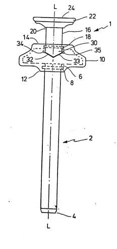
The version of a flexible cannula according to the invention
shown in Figure 1 consists of a top piece 1 and a tube 2. The
tube 2 has essentially the shape of a hollow cylinder and can be
bevelled at its distal end 4. Attached in the vicinity of its
proximal end 6, on the outside of the tube 2 is an annular
protrusion 8 with the help of which the tube 2 is secured at the
top piece 1. The tube 2 is made from a flexible material.
.',",',',
6 - ~ 1~ 8 38 ~
A hou~ing 10 with a distal end wall 12 and a proximal end wall
14 is joined to the proximal end 6 of the tube 2. The distal
end wall 12 is provided with an opening which is concentric to
the longitudinal axis L-L of the cannula and whose diameter is
the same as the diameter of the tube 2. An annular recess for
housing the protrusion 8 runs round the opening. The housing 10
preferably consists of two housing halves which are connected to
each other in gas-tight manner, for example glued, so that the
assembling of the tube 2 is unproblematical despite the
protrusion 8.
A flexible intermediate tube 16 with an annular protrusion 18 is
mounted in the proximal end wall 14, similar to the attachment
of the tube 2 to the distal end wall 12. The intermediate tube
16 is made from a flexible material and runs concentrically
relative to the longitudinal axis L-L. Its internal diameter can
be the same as that of the tube 2, but can also be greater.
The intermediate tube 16 carries a coupling part 22 at its
proximal end 20. As can be seen in Figure 3, the proximal end
face 24 of the coupling part 22 is provided with an opening 26.
The opening 26 in the proximal end face 24 is essentially
aligned with the cross-section surface of the tube 2; the
diameter of the opening 26 can be somewhat greater than the
internal diameter of the tube 2. In the embodiment, the opening
26 is surrounded by an annular seal 27 which is made from a
flexible plastics material. The internal diameter of the seal
27 is preferably smaller than the internal diameter of the tube
2. The result of this is that the seal 27 lies securely against
the shaft of an operation instrument introduced through the
opening 26, even if the diameter of the shaft should be somewhat
smaller than the internal diameter of the tube 2. On the other
hand, the somewhat greater diameter of the opening 26, acting
together with the flexible seal 27, per~lts a certain mobility
for the inserted endoscopic operation instrument. - The seal
;. ..
- 7 -
could also be designed differently, e.g. as an O-ring arranged
further inwards (i.e. displaced in distal direction).
Located at the proximal end face 24 are coupling elements 28 for
securing additional equipment (such as e.g. a trocar or a
reduction cap) which can be fitted onto the proximal end face
24. In the embodiment, the coupling elements are designed as
two recesses 28, provided with projections, in the wall of the
coupling part 22. The pro~ections are engaged by corresponding
pro~ection~ at securing clips which are attached to the
additional equipment to be fitted, so that a secure mechanical
connection results. The connection can be released in the usual
way by moving the distal end zones of the securing clips with
the corresponding projections onto the axis L-L.
A closure device is arranged in the inside of the housing 10.
A part of this closure device is a closure sleeve 30. In the
embodiment, the closure sleeve 30 is designed in one piece with
the flexible intermediate tube 16 and is thus held via the
annular protrusion 18. The closure sleeve 30 has the same
internal diameter as the flexible intermediate tube 16 and is
cut at an angle on both sides, as shown in Figure 1. The distal
edge of the closure sleeve 30 forms a sealing surface against
which two plane plates can lie, the angle between the plates
being smaller than 180 degrees, see Figure 1. Here the wings 32
and 33 of a double flap serve as sealing plates. Arranged at a
distance from the longitudinal axis L-L which is greater than
the external radius of the closure sleeve 30 are a bearing
element 34 connected to wing 32 and a bearing element 35
connected to wing 33. The ends, designed as trunnions, of the
bearing elements 34, 35 are placed in corresponding recesses in
side walls 36 and 37 of housing 10, see Figure 2. As Figure 2
also shows, the length of the wings 32 ~hatched in Figure 2) and
33 is great enough to cover the closure sleeve 30 completely,
while on the other hand there is enough play in the housing 10
83 8 ~
to allow a free swivel movement of the wings 32 and 33. The
wings 32 and 33 are pressed against the distal edge of the
closure sleeve 30 by springs which are not represented in the
Figures. In order to achieve an adequate sealing effect, the
distal edge of the closure sleeve 30 can be provided with a seal
lining; alternatively, wings 32 and 33 can also be appropriately `
equipped. At their free ends, wings 32 and 33 meet on the
longitudinal axis L-L, where they likewise form a sealing -~
surface. Upon introduction of an operation instrument into the
flexible cannula, it~ distal end pushes the two wing~ 32 and 33
against the elastic force in distal direction. When the
instrument is withdrawn, the wings 32 and 33 automatically close
under the action of the springs and thus prevent the compressed - -
gas from escapin~ from the inside of the body. ~ -~
In order that the closure device can also be actuated manually,
both bearing elements 34 and 35 can, for example, be guided
right through the side wall 36 or 37 on one side (not shown in ;~ -
the Pigures) in gas-tight manner. If a lever is attached in each ~ -
case to the outward-lying ends, wings 32 and 33 can easily be
folded away in distal direction. Alternatively, only one of the
bearing elements 34 or 35 could be passed through one of the
side walls 36 or 37 if the two wings 32 and 33 are so coupled in
the inside of the housing 10 that the swivelling of the wing
connected to the passed-through bearing element simultaneously
effects the swivelling of the other wing. The double flap can
al80 be ~o designed that the wings 32 and 33 come together at an
angle of 180 degrees, i.e. that the distal edge of the closure
sleeve 30 lies in one plane. The advantage of designing the
closure device as a double flap is the small structural height.
In an alternative version, the closure device is a flat slide
valve. Flat slide valves are known, for example from vacuum
technology. In a flat slide valve, opening or closure is
effected by moving a flat closure part in a direction which runs
':
,: 1 :.:
. .
: ..
21~38~ ~
g
.:. .~ .
essentially perpendicular to the axis of the opening to be
closed, so that a small structural height is possible in the
direction of this axis. As a flat slide valve cannot be opened
directly from the distal end of an operation instrument which is
moved essentially along said axis, it must be actuated
separately. This can take place manually, for example.
A usual gas connection with a valve or a manual actuation system
for supplying gas into the inside of the body can be provided at
the side wall 36 or side wall 37 of the housing lO.
The tube 2 and the intermediate tube 16 are made from a flexible
material suitable for medical purposes, for example silicone or
polyurethane.
The individual parts of the flexible cannula according to the
invention are so fitted together that, when the closure device
is closed, a space which is sealed off in a gas-tight manner is
formed underneath the closure device, which space communicates
with its surroundings only via the opening at the distal end 4
of the tube 2. ~hen the closure device is opened and an
operation instrument inserted, the same applies to the whole
space underneath the seal 27 which lies against the shaft of the
introduced operation instrument.
Figure 4 shows the inventive flexible cannula according to the
described embodiment together with an introduced trocar 40. The
trocar 40 has a shaft 42 whose external diameter corresponds to
the internal diameter of the tube 2 or is somewhat smaller. At
its distal end, the shaft 42 carries a trocar point 44 with the
help of which a puncture point is produced in the body wall.
Attached to the pro~imal end of the shaft 42 is a handling part
46 which serves to advance the trocar point 44. Attached to the
handling part 46 and serving as coupling elements are two
securing clips which can be pressed inwards with the help of two
~ "
.
' .. ..
-? 21~38~
. ~
: :.
push buttons 48 in order to release the connection, as described
earlier. It can be seen from Figure 4 how the shaft 42 of the
trocar 40, similarly to the shaft of another introduced
endoscopic operation instrument, opens the wings 32 and 33 of
the closure device. Where appropriate, additional equipment
other than the trocar 40 can also be connected via the coupling
part 22 to the flexible cannula according to the invention.
In an alternative version of a flexible cannula according to the
invention, the tube is made from a flexible material and the top
piece is designed flat when seen in the direction of the
longitudinal axis of the cannula. In this case, the top piece
is not divided into several components as in the previous
embodiment, but both the closure device and the opening at the
proximal end face with the associated seal and the coupling
elements are integrated in a single housing which is attached to
the proximal end of the tube. In this embodiment, there is no
flexible intermediate tube provided. In order to make possible
the flat mode of construction of the housing, the closure device
can be designed for example as a space-saving double flap of the
type described above or as a flat slide valve. Because of the
small extension of the top piece in the direction of the
longitudinal axis of the cannula, the introduction of a bent
operation instrument is not impeded, although the top piece
itself is rigid.
.. ..
' '` .','.',.
~'