Language selection

Search

Patent 2108410 Summary

Third-party information liability

Some of the information on this Web page has been provided by external sources. The Government of Canada is not responsible for the accuracy, reliability or currency of the information supplied by external sources. Users wishing to rely upon this information should consult directly with the source of the information. Content provided by external sources is not subject to official languages, privacy and accessibility requirements.

Claims and Abstract availability

Any discrepancies in the text and image of the Claims and Abstract are due to differing posting times. Text of the Claims and Abstract are posted:

  • At the time the application is open to public inspection;
  • At the time of issue of the patent (grant).
(12) Patent: (11) CA 2108410
(54) English Title: STREAMLINED AIR CONDITIONING DISCONNECT SWITCH
(54) French Title: INTERRUPTEUR PROFILE POUR APPAREIL DE CLIMATISATION
Status: Deemed expired
Bibliographic Data
(51) International Patent Classification (IPC):
  • H01H 3/02 (2006.01)
  • H01H 15/02 (2006.01)
  • H02B 1/48 (2006.01)
(72) Inventors :
  • REICHOW, MATT (United States of America)
  • OLSON, RANDALL M. (United States of America)
(73) Owners :
  • GENERAL ELECTRIC COMPANY (United States of America)
(71) Applicants :
  • GENERAL ELECTRIC COMPANY (United States of America)
(74) Agent: CRAIG WILSON AND COMPANY
(74) Associate agent:
(45) Issued: 2002-05-14
(22) Filed Date: 1993-10-14
(41) Open to Public Inspection: 1994-05-24
Examination requested: 1998-04-23
Availability of licence: N/A
(25) Language of filing: English

Patent Cooperation Treaty (PCT): No

(30) Application Priority Data:
Application No. Country/Territory Date
979,922 United States of America 1992-11-23

Abstracts

English Abstract


An air conditioning disconnect switch utilizes a
ramped movable contact arrangement for slidably opening and
closing the switch contacts without the requirement of a
removable type pull-out handle. A plastic face plate
covering the switch terminals allows the use of a metallic
case of reduced depth. The slidable contact arrangement
eliminates the bumped cover projection otherwise required
with the pull-out handle.


Claims

Note: Claims are shown in the official language in which they were submitted.


-7-


CLAIMS:

1. An electric disconnect switch comprising:
a rectangular case;
a cover hinged to said case;
a plastic terminal block within said case, said terminal block
including a plurality of busbar contacts connecting with a plurality of
terminal lugs arranged on a terminal support;
a handle operator having a plurality of contact blades
extending from a bottom surface slidably arranged on said terminal block
and a handle post extending upwards from a top surface, said contact
blades moving in and out of contact with said busbar contacts in
response to manual movement of said handle posts between ON and OFF
positions;
a plastic face plate arranged over said terminal support to
electrically isolate said terminal lugs; and
a plastic support housing arranged over said handle
operator, said support housing comprising a planar top and a central
ramp extending from said top at a predetermined acute angle, said central
ramp including a rectangular handle access slot, said handle post
extending within said handle access slot, said handle operator including
a contact spring extending from a top surface, said contact spring
interacting with a bottom surface of said support housing top to provide
contact pressure between said contact blades and said busbar contacts
when said handle post is in an ON position.

2. The disconnect switch of claim 1, wherein said handle
operator comprises a triangular body.

3. The disconnect switch of claim 1, wherein said support
housing includes a rectangular side coextensive with said central ramp,


-8-


said support housing top and said support housing side each including
integral tabs supporting one end of said face plate.

4. The disconnect switch of claim 1, wherein, said contact
spring comprises a planar end and an angulated end, said planar end
being fastened to said handle operator top surface and said angulated
end extending up-right from said handle operator top surface.

5. An electric disconnect switch comprising:
a rectangular case;
a cover hinged to salt case;
a plastic terminal block within said case, sad terminal block
including a plurality of busbar contacts connecting with a plurality of
terminal lugs arranged on a terminal support;
a handle operator having a plurality of contact blades
extending from a bottom surface slidably arranged on said terminal block
and a handle post extending upwards from a top surface, said contact
blades moving in and out of contact with said busbar contacts in response
to manual movement of said handle post between ON and OFF positions;
a plastic face plate arranged over said terminal support to
electrically isolate said terminal lugs; and
a plastic handle operator guide comprising a triangular body
having a ramped elongated rectangular handle support slot, said handle
post being arranged within said handle support slot.

6. The disconnect switch of claim 5, wherein said handle
operator further includes a planar apron supporting said handle post, said
apron defining a pair of runners extending from opposite edges and
arranged on a corresponding pair of tracks integrally-formed on opposite
sides of said handle support slot.


-9-


7. The disconnect switch of claim 5, wherein said triangular
body further includes a locking block integrally-formed on one side
thereof.

8. The disconnect switch of claim 7, wherein said terminal
support includes a plurality of terminal compartments, a central one of
said compartments receiving said locking block in press-fit relation.

9. The disconnect switch of claim 5, wherein said terminal
block further includes an upstanding perimetric wall defining a rectangular
cavity, said busbar contacts being recessed within said cavity.

10. The disconnect switch of claim 9, including a plurality of
upstanding barriers intermediate said terminal compartments electrically
isolating said terminal lugs.

11. The disconnect switch of claim 5, wherein said case is
metal.

12. The disconnect switch of claim 5, wherein said cover is
metal.
Description

Note: Descriptions are shown in the official language in which they were submitted.


41 PR07024
-1-
STREAMLINED AIR CONDITIONING DISCONNECT SWITCH
BACKGROUND OF THE INVENTION
U.S. Patent 4,675,782 entitled "Molded Plastic
Enclosure for Disconnect Switches" describes a switch
contained within a plastic enclosure wherein the plastic
multi-functionally provides support and electrical
insulation to the electrical fuses and other electrical
components contained therein. For some non-fused
applications, a less expensive disconnect switch contained
within.a metal enclosure can be employed.
U.S. Patent 4,851,963 entitled "Weatherproof Air
Conditioning Disconnect Switch" describes a simple switch
enclosed within a metal enclosure that includes a pull-out
handle that carries the movable contacts in and out of
connection with the fixed contacts arranged within the
switch housing. To prevent inadvertent replacement of the
handle when the air conditioning equipment is being
installed or repaired, the operator may retain the handle
until such repair or installation is completed. The loss
or misplacement of the handle could cause needless delay in
obtaining a replacement before the equipment could become
operational.
The use of residential type circuit breakers within
the enclosure in place of the pull-out handle insures that
the equipment can be turned on and off without removing and
perhaps misplacing the operating handle. Such circuit
breakers operate efficiently to both protect and control
the associated equipment but add to the overall cost.


~~~y~~~~ 41PR07024
-2-
One purpose of the invention is to provide an
electric disconnect switch of reduced dimensions that
operate within a metal enclosure without the requirement of
circuit breakers to turn the associated electric equipment
on and off.
SUMMARY OF THE INVENTION
An electric disconnect switch for air conditioners
and other electrical equipment that are turned on and off
from a remote location includes a plastic switch assembly
contained within a metal enclosure. A ramped movable
contact arrangement slidably moves the switch contacts
between their on and off conditions. A plastic face plate
ensures proper over-surface electrical clearance while
containing information and caution indicia
integrally-formed therein.
BRIEF DESCRIPTION OF THE DRAWINGS
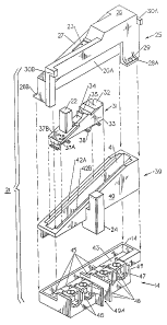
Figure 1 is a top perspective view of an air
conditioning disconnect switch according to the prior art
with the face plate removed to detail the operating
components;
Figure 2 is a similar top perspective view of an air
conditioning switch according to the invention;
Figure 3 is a top perspective view of the operating
components within the switch of Figure 2 prior to assembly;
and
Figure 4 is a side sectional view of the switch of
Figure 2.


41 PR07024
2~.~~~.
-3-
DESCRIPTION OF THE PREFERRED EMBODIMENT
An air conditioning disconnect switch l0 sirnilar to
that described within aforementioned U.S. Patent 4,851,963
is depicted in Figure 1. The switch includes a metal case
11 to which a metal cover 12 is hinged. A plastic face
plate 13 which includes indicia formed therein is
positioned over the terminal block 14 to prevent
inadvertent contact with the terminal lugs 15 carried on
the block and the ground terminal connector 17 attached
directly to the case. Electrical access with the interior
of the switch is made by means of knockouts 18 formed in
the sides of the case and clearance for the handle operator
16 is provided by means of the depression 19 formed on the
inside surface of the cover 12. As described in the
aforementioned U.S. Patent 4,851,963, the switch is turned
on and off by removal of the handle operator from the
terminal block to correspondingly make and break connection
between the terminal lugs 15.
To facilitate inventory requirements as well as to
minimize cost, the novel disconnect switch 20 depicted in
Figure 2 has common components with the switch 10 shown
earlier and cortanon reference numerals will be used where
possible. The switch 20, for example, comprises a metal
case 11 to which a similar metal cover 12 is hinged and a
plastic face plate 13 is used to protect the terminal block
14 and ground connector 17. The terminal block 14 captures
the locking block 24 integrally-formed on a side of the
switch operator assembly 21 in a manner to be described
below in greater detail. The switch operator includes a
handle post 22 extending up through a rectangular handle
access slot 23 which allows an operator to turn the switch
on and off in the manner to be described below.


~ ~ ~ ~~,a ~ ~ ~ 41 PR07024
_4_
As best seen by referring now to Figure 3, the switch
operator assembly 21 includes a support housing 25 formed
from a molded plastic composition which includes a planar
top 26 and a central ramp 27 depending down from the top at
a predetermined acute angle. A rectangular side piece 26A
coextends along the ramp and includes a support tab 30B
which cooperates with a similar support tab 30A extending
from the top to support the front plate 13 shown earlier in
Figures 1 and 2. A pair of opposing fastening tabs 28A,
288 extending from the bottom of the support housing and
include thru-holes 29 to facilitate attachment of the
support housing to the case. The handle post slot 23 is
formed within the ramp and captures the handle post 22
integrally-formed within the handle operator 31: The
handle operator is a separate element also formed from a
molded plastic material and includes a planar top 32 which
sits under the top 26 of the support housing and a camped
apron 36 which depends downward from the top 32 at the same
predetermined angle described earlier.
The handle operator 31 consists of a molded plastic
triangular body 33 to which a pair of U-shaped contact
blades 38 which comprise the movable switching contacts are
attached. A planar contact spring 34 is attached to a top
part of the apron and includes an angulated end 35 that
interfaces with the inner surface of the central ramp in a
manner to be described below. A pair of runners 37A, 37B
extend from opposite sides of the apron 36 and overlay the
tracks 42A, 428 formed on opposite sides of the camped
elongated rectangular handle support slot 41 defined within
the molded plastic triangular body 40 of the handle
operator guide 39. The locking block 24 is


41 PR07024
-5-
integrally-formed with the body 40 and extends from a side
of the body for press-fit capture within the central
terminal recess 49A formed within the terminal support 4fi
on one side of the terminal block 14. The remaining
terminal recesses 49 outboard the central recess contain
the terminal lugs 48 each of which is connected with a
corresponding planar busbar contact 45 which comprise the
stationary contacts. The busbar contacts are positioned
within the bottom of the rectangular cavity 43 surrounded
by the upstanding perimetric wall 44. The upstanding
barriers 47 integrally-formed within the terminal block
define the terminal recesses 49 formed within the terminal
support 46 and provide the requisite electrical isolation
to the terminal lugs contained therein.
The operation of the switch 21 between the "ON" and
"OFF" conditions depicted in phantom and in solid lines
respectively in Figure 4 is as follows. In the OFF
position, the handle post 22 on the handle operator 31 is
at the uppermost edge of the rectangular handle access slot
23 and the angulated end 35 of the-contact spring 34 is in
an extended relaxed condition under the inner surface 27A
of the central ramp 27 of the support housing 25. The
U-shaped contact blades 38 are above and out of contact
with the busbar contacts 45 that are recessed within the
bottom 43A of the rectangular cavity 43 defined within the
terminal block 14. Sliding the handle post downward within
the access slot 23 to the opposite edge, compresses the
angulated end 35 of the contact spring 34 against the
bottom surface 27A of the central ramp 27 and forces the
U-shaped contact blades in bridging contact with adjacent
pairs~of the busbar contacts 45 thereby turning the switch


41P 807024
-6-
to its ON condition. Moving the handle post upwardly
within the access slot to the opposite edge lifts the
U-shaped contact blades away from and out of electric
contact with the busbar contacts to return the switch to
its OFF position.
A slidabiy-operated disconnect switch has herein been
described utilizing a tamped support housing, tamped handle
operator and tamped handle guide to provide a streamlined
configuration within a switch enclosure of reduced overall
dimensions.

Representative Drawing
A single figure which represents the drawing illustrating the invention.
Administrative Status

For a clearer understanding of the status of the application/patent presented on this page, the site Disclaimer , as well as the definitions for Patent , Administrative Status , Maintenance Fee  and Payment History  should be consulted.

Administrative Status

Title Date
Forecasted Issue Date 2002-05-14
(22) Filed 1993-10-14
(41) Open to Public Inspection 1994-05-24
Examination Requested 1998-04-23
(45) Issued 2002-05-14
Deemed Expired 2010-10-14

Abandonment History

There is no abandonment history.

Payment History

Fee Type Anniversary Year Due Date Amount Paid Paid Date
Application Fee $0.00 1993-10-14
Registration of a document - section 124 $0.00 1994-05-10
Maintenance Fee - Application - New Act 2 1995-10-16 $100.00 1995-09-20
Maintenance Fee - Application - New Act 3 1996-10-14 $100.00 1996-09-19
Maintenance Fee - Application - New Act 4 1997-10-14 $100.00 1997-09-18
Request for Examination $400.00 1998-04-23
Maintenance Fee - Application - New Act 5 1998-10-14 $150.00 1998-09-16
Maintenance Fee - Application - New Act 6 1999-10-14 $150.00 1999-09-24
Maintenance Fee - Application - New Act 7 2000-10-16 $150.00 2000-09-28
Maintenance Fee - Application - New Act 8 2001-10-15 $150.00 2001-09-27
Final Fee $300.00 2002-02-14
Maintenance Fee - Patent - New Act 9 2002-10-14 $150.00 2002-09-19
Maintenance Fee - Patent - New Act 10 2003-10-14 $200.00 2003-09-22
Maintenance Fee - Patent - New Act 11 2004-10-14 $250.00 2004-09-21
Maintenance Fee - Patent - New Act 12 2005-10-14 $250.00 2005-09-21
Maintenance Fee - Patent - New Act 13 2006-10-16 $250.00 2006-09-18
Maintenance Fee - Patent - New Act 14 2007-10-15 $250.00 2007-09-17
Maintenance Fee - Patent - New Act 15 2008-10-14 $450.00 2008-09-17
Owners on Record

Note: Records showing the ownership history in alphabetical order.

Current Owners on Record
GENERAL ELECTRIC COMPANY
Past Owners on Record
OLSON, RANDALL M.
REICHOW, MATT
Past Owners that do not appear in the "Owners on Record" listing will appear in other documentation within the application.
Documents

To view selected files, please enter reCAPTCHA code :


To view images, click a link in the Document Description column. To download the documents, select one or more checkboxes in the first column and then click the "Download Selected in PDF format (Zip Archive)" or the "Download Selected as Single PDF" button.

List of published and non-published patent-specific documents on the CPD .

If you have any difficulty accessing content, you can call the Client Service Centre at 1-866-997-1936 or send them an e-mail at CIPO Client Service Centre.


Document
Description 
Date
(yyyy-mm-dd) 
Number of pages   Size of Image (KB) 
Drawings 2001-09-04 4 99
Claims 2001-07-19 3 101
Drawings 2001-07-19 4 203
Abstract 1995-03-18 1 12
Claims 1998-07-30 3 102
Cover Page 2002-04-16 2 43
Description 1995-03-18 6 188
Cover Page 1995-03-18 1 64
Claims 1995-03-18 3 156
Drawings 1995-03-18 4 233
Representative Drawing 1998-08-27 1 20
Representative Drawing 2001-08-24 1 14
Prosecution-Amendment 2001-04-26 2 63
Assignment 1993-10-14 6 230
Prosecution-Amendment 1998-04-23 8 265
Prosecution-Amendment 2001-07-19 4 132
Correspondence 2002-02-14 1 30
Fees 1996-09-19 1 52
Fees 1995-09-20 1 51