Note: Descriptions are shown in the official language in which they were submitted.
CA 02108537 2004-07-13
WEAR RODS FOR SKIS OF SNOWMOBILES AND SIMILAR VEHICLES
Field Of The Invention
The invention is directed to improvements in wear rod
design to better control the steering behaviour of snow-
mobiles and similar vehicles.
Background Art
Prior art provides very little design range to change
steering effort or control. Traditional wear rod design
consists of a round rod performing two functions - turning
and wear protection of the ski base.
The steering bias in this system is uncontrollable.
The length of wear rod in front of the turning centre of
the ski is greater than that which is behind. This allows
self energizing behaviour or wander.
The only way a traditional wear rod can increase its
turning ability is to go longer to the rear or larger
diameter. The lengthening far from the durning centre
makes extreme additions to turning effort because of the
leverage. If a larger rod is used then steering effort
again increases as does self energizing problems.
One attempt marketed today uses a separate flat
carrier with an added round conventional rod in a shortened
form. This has the obvious problem of inadequate turning
ability. It is also difficult in this system to provide
different options of round rod length with existing bolt
patterns.
All round rods have problems of penetration into hard
snow with wear because the contract width increases. It
CA 02108537 2004-07-13
2
then requires more weight to penetrate properly.
Snowmobiles are very sensitive to this problem.
Summary Of The Invention
This invention comprises improved wear rods for
snowmobiles. They consist of cross sectionally rectangular
components to separate the protective and steering
functions of the wear rods to enhance their abilities. The
horizontal component of the rod allows the protection of
the ski base without creating any steering ability and bias
problems. It allows the adaptation to any bolt pattern for
mounting to the ski. It also provides improved strength to
resist lateral bending with much better mechanical
advantage and that strength is much less affected by wear.
The horizontal component also allows the mounting bolts and
vertical component to be offset for ease of access to mount
bolts and better structural support from the ski for the
vertical component.
The vertical rectangular component of the rod allows
the contact width of the rod to remain the same with wear.
This provides consistent penetration without having to
adjust ski bearing pressure. The height and length
selections for the vertical component can be chosen based
on rider preferences and demand. The position of the
vertical component front and rear can a controlled to
achieve desired bias relationship.
Traditional skis have steering engagement surfaces
incorporated into their bases. These longitudinal keels
are un-adjustable and create bias problems for designers.
Because the mount bolt or load application point for the
ski must be to the rear to the ski centre, this keel
CA 02108537 2004-07-13
3
creates self energizing steering behaviour. A wear rod of
the present invention needs no such keel.
Greater steering control by the wear rod and not the
keel allows for a much wider range of adaptability with
simple wear rod change.
Wear resistant carbide inserts are of critical
importance to control wear rates on hard surfaces with this
design.
According to one aspect of the present invention,
there is provided a wear rod for skis of snowmobiles and
similar vehicles, comprising a generally flat horizontal
base for engaging an underside of a ski and a generally
vertical wear element projecting downwardly from the
horizontal base, wherein said base extends in a lateral
direction by a greater extent than said wear element.
According to another aspect of the present invention,
there is provided a wear rod for skis of snowmobiles and
similar vehicles, comprising a generally flat horizontal
base for engaging an underside of a ski, a generally
vertical wear element projecting downwardly from the
horizontal base, and at least one bolt upstanding from said
base forming an attachment for mounting said wear rod said
ski, wherein said base and said bolt are offset laterally
from a vertical longitudinal plane of said base on opposite
sides of said plane.
According to yet another aspect of the present
invention, there is provided a steering ski for a
snowmobile or similar vehicle having a ski element and a
wear rod attached to a lower surface of said ski element,
said wear rod comprising a generally flat horizontal base
for engaging said lower surface of said ski element and a
generally vertical wear element projecting downwardly from
CA 02108537 2004-07-13
4
the horizontal base, wherein said base extends in a lateral
direction of said ski by a greater extent than said wear
element.
According to yet another aspect of the invention,
there is provided a wear rod for skis of snowmobiles and
similar vehicles, comprising a generally flat horizontal
base for engaging an underside of a ski and a generally
vertical wear element projecting downwardly from the
horizontal base, wherein said base has dimensions of about
1/8 x 1 x 28 inches and said wear element has dimensions of
about 1/8 x 3/4 x 22 inches.
Description Of The Drawing
Fig. 1 shows a traditional ski and wear rod
configuration;
Fig. 2 is a cross section at A-A of Fig. 1;
Fig. 3 is a side elevation of a ski having a wear rod
according to one form of the present invention;
Figs. 4A and 4B are cross sections of right and left
skis of the type shown in Fig. 3 taken along line at B-B;
Fig. 5 shows a traditional wear rod cross section
provided with a carbide wear insert;
Fig. 6A is a cross section of a wear rod according to
one form of the present invention;
Fig. 6B is a cross-section similar to that of Fig. 6A
showing an alternative wear rod according to the present
invention;
Fig. 7A and Fig. 7B show cross sections of wear rods
according to the present invention in offset forms making
left and right wear_ rods; and
CA 02108537 2004-07-13
Fig. 8 is a cross-section of a traditional ski and
wear rod showing collapse above the wear rod.
Description Of The Preferred Embodiment
5
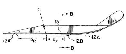
Figure 1 shows a traditional ski 10 and wear rod 12.
Dotted line C represents the turning centre of the ski with
a common caster angle. Point b is the point of contact
from which bias is measured. bf is the front length of the
wear rod and br is the rear length of the wear rod. Note
that bf can change depending on snow conditions and ski
flotation depth but it invariable changes for the worse.
In order for a ski to behave properly bf should be shorter
than br which they are not. This creates wander and
dangerous self energizing behaviour.
Figure 2 is a cross section of the ski and wear rod of
Fig. 1 taken along line A-A. Note the ski mount bolt 13
location in Figure 1 which must be to the rear of centre to
have the ski perform properly by floating up in the snow.
This requirement is a major problem with Figure 2 type
cross sections.
Figure 3 is a ski having a wear rod design according
to the present invention. Note the flat horizontal
component 12A extends to the front to the ski without
imparting any turning ability or bias problems. It serves
as a protective surface. Note also the favourable bias
relationship of bf to br.
Figure 4 is a view of the system in Figure 3 in cross
section along the line B-B. This Figure shows the cross
section of a pair of skis in their normal orientation as
seen from the rear. The wear rod mount bolts 13 are
readily accessible along the inner edge of the ski and the
CA 02108537 2004-07-13
6
vertical wear rod component 12B is well supported by the
vertical structure 15 on the top side of the ski. This is
a important feature to prevent collapse of the ski base
upwardly when hard impact forces are encountered.
Figure 5 shows a conventional wear rod.
Figures 6A shows one form of a wear rod according to
the present invention in cross section with top mount bolt
13, horizontal rectangular component 12A and vertical
rectangular component 12B. In this embodiment, the
vertical component is thin and generally rectangular. In
an alternative form shown in Fig. 6B, the vertical
component 12B is generally triangular as shown.
Figures 7A and 7B are cross sections of an opposing
pair of another form of the invention where the mount bolts
13 and vertical components 12B are offset to allow better
bolt access and better support of the vertical component.
Figure 8 shows a conventional cross section of a ski
10 and wear rod 12 showing collapse of the ski keel 18 over
the wear rod due to impact with hard objects such as rock.
This drastically reduces the wear rod's function.
The cross sectional dimensions of the components of
the wear rod of the invention are preferably: horizontal
1/8 x 1 x 28 inches and vertical 1/4 x 3/4 x 22 inches with
2 inches of rear bias.