Note: Descriptions are shown in the official language in which they were submitted.
210862~
~TI~OD ~OR I~I~ATINa A ROLL AND A B~A'rA~L~ R45.L,
IN ~?!R~ICUI~R A PR~58ll R,O~Q~AI~ER IIACIIINIS
BAC~GROUND OF T~IE INVENTION
The invention relates to a heatable roll, in partlcular a
press roll or equivalent for a paper machine, which directly
contacts a paper web running in the press section of a paper
machine.
The invention also relates to a method for heating a roll
located in a press section in which a heat transfer medium
circulates through the roll.
In the prior art, a rock roll made of granite is frequently
1~ used in the press section of a paper machine. Granite is usQd
because of its advantageous surface properties which provlde
controlled detaching of the paper web from a face of the rock
roll. Moreover, granite has a high resistance to the wearing
_ ef~ect of a doctor used in the press section.
However~ the use of granite for a roll in a press section
has certain drawbacks. One drawback is that because granite is a
natural material, its material properties vary. Thus, internal
flaws in the granite, combined with a tendency to crack partly as
~, a result of the internal flaws, form serious obstacles for using
25`` granite in some press section applications, particularly
applieations at high temperatures. In addition, a granite roll
is heavy and comprises an inhomogeneous material, both factors
which increases the tendency of oscillations of the roll
eonstruetions which is another significant drawbaek reducing the
~` .
210~62~
operating efficiency of the press section. The heavy weight o a
rock roll made of granite is also con~idered when selecting the
dimensions of the lifting equipment and foundations required for
the paper machine.
In other prior art constructions, synthetic rock rolls are
also known. These synthetic rock rolls are in principle
polymer-coated rolls in which a rock powder, such as quartz sand,
iB mixed into hard rubber or polyurethane to thereby form a
synthetic rock roll. Drawbacks of these rolls include excessive
adhesion of the paper web to the roll face inhibiting detachment
as well as poor mechanical strength and limited heat tolerance.
In prior art paper machines, a process called hot pressing
is known in which the temperature of the web is raised in order
to achieve a higher dry solids content in the pressing stage. In
this manner, significant savings can be obtained with respect to
the drying requirements in the drying section of the paper
machine.
The heating of a press roll in a press section takes place
most advantageously from the interior of the roll. Drawbacks of
an external heating methods, such as induction-infrared heating,
include the high cost of acquisition and operation of devices to
provide such external heating, and the requirement of space for
~ the devicGs.
~eatable extended-nip presses have been described earlier,
e.g., in U.S. Patents 4,738,752 and 4,874,469, whose drawbacks
include high consumption of power as a result of the heating of
the rolls in the extended-nip.
When heating rolls in press sections, it is also known in
the prior art to introduce heat into the roll through bores
formed into the roll mantle. In these bores, a heating medium,
~uch as hot oil, water or steam, is circulated. A solution of
this type is described, e.g., in Canadian Patent CA 1,233,763.
21~862~
However, a drawback of this solution of heatinq the roll i~ the
high consumption of power required to produce the heat, as well
ns local deformations in the roll mantle because of the
differences in temperature in the roll face in the
circumferential direction.
From published European Patent Application EP 0 471 655, a
heatable roll is Xnown in which the roll mantle is heatèd by
means of electric resistors arranged in ducts formed in the roll
mantle. In the embodiment described therein, it possible to make
the variations in temperature in the roll face quite low in order
- to avoid local deformations.
With regard to heating a roll in a drying section from the
'_ interior, it is known in the prior art to heat the roll mantle by
means of steam (e.g. Yankee cylinder, Tem Sec~). However, in
such a case the heat transfer that takes place through the roll
mantle restricts or hampers the attempt to provide an efficient
heating effect, which results, e.g., in a need to increase the
diameter of the roll.
Differences in the temperatures of the incoming paper web or
2A fQlt, as well as transverse air flows in the press section, tend
to produce an uneven distribution of temperature in the roll
face, in particular when the temperatures are high. Uncontrolled
differences in temperature produce undesirable deformations in
the roll and, further, problems in controlling the transverse
as profiles of the web. This phenomenon is particularly detrimental
in ro~ 18 whose coatings have a low capacity of thermal
insulation, such as in the case of non-porous metallic coatings.
In addition, polymer coatings are unsuitable for rolls heated
from inslde because they have a limited heat tolerance and their
heat transfer capacity is inadequate.
In heatable rolls, in particular in rolls substituted for
earlier rock rolls in the press sections of paper machines, it is
` ` ` 210862~
known to provide the roll face with a coating Or a ceramic
material. Such solutions are described, e.g., in U.S. Patent
4,704,776 and in published Finnish Patent Applicatlon No. FI
84,506. ~owever, a method of heating the rolls i8 not described
in these publications.
0BJ~CT8 AND 8UMMARY OF THB ~NV~N~ION
An object of the present invention is to provide a heatable
roll, in particular a press roll for a paper machine, by who~e
means the drawbacks related to the prior art rolls are
eliminated.
It i5 another ob~ect of the present invention to provide a
~_ new and improved heatable roll by whose means an improvement is
provided over the heatable rolls currently in use.
It is yet another ob~ect of the present invention to heat
press rolls in an efficient and improved manner by circulating a
heat transfer medium through the rolls in proximity to the outer
face of the rolls.
In view of achieving these objects and others, in the
ao preBent invention a roll is heated by flowing a heat transfer
medium into the roll so that the roll is heated from its
interior. An outer face of the roll is provided with a coating
~ made of ceramic, a metal-ceramic mixture, a porous metal or an
equivalent material whose thermal conductivity and modulus of
elasticity are lower than the corresponding properties of the
material of the roll body.
By means of the present invention, a number of advantages
are obtained as compared with the prior art, of which advantages,
e.g., the following should be stated in this connection. In the
invention, a circulating heat transfer medium, such as hot water,
oil or steam, is used for the heating of the roll. The constant
clrculation of the heat transfer medium equalizes the temperature
.f~
210862~
differences between different polnts on the roll and reduces the
ri~k of thermal crown formation.
In a roll in accordance with the invention, the heating of
the roll is carried out from inside the roll by introduclng the
heat as close as possible to the outer face of the roll. The
transfer of heat ta~ing place through a wall of the roll and the
coating on the roll, and the capacity of heat delivery, wlll not
be equally decisive as in prior art constructions.
Further, by introducing the heat in proximity to the roll
lo face, an advantage is obtained in that the temperature of the
heat transfer medium does not need to be raised to an equally
high level as compared to the situation where the heat is
introduced by means of a heat transfer medium onto an inner face
of the roll mantle. In addition, it is possible to use low-cost
energy for heating, so that the heat transfer medium is heated by
means of waste steam.
The roll in accordance with the invention is heated by means
of ducts formed in the interior of the walls of the roll mantle
and by means of a heat transfer medium (preferably water) flowing
an in the ducts. As a result of this arrangement, the roll does not
become a pressure vessel, which is the case, e.g., in rolls
heated by means of steam from inside the roll mantle. In
addition, the roll of the present invention is constructed
simpler than in the case of a pressure vessel, and does not
as require approval by the appropriate authorities or aompliance
with spplicable regulations.
In the roll in accordance with the invention, large flows of
heat ~re easily produced. Ducts in the roll mantle are placed
close to the roll face so that the thermal resistance of the
material of the roll mantle is lower and a larger amount of heat
can be transferred with the same temperature difference within
the ~ame unit of time than if the ducts were placed further apart
~:`
. . 210862~
from the roll face. Owing to the low thermal resistance, the
temperature difference in the roll mantle i~ little, 80 that the
thermal stresses arising from it ars also lower. ~he ease Or
manufacture may also be considered as an advantage over prior art
constructions.
The coating used in a roll in accordance with the invention
is preferably a thermally sprayed ceramic, metal-ceramic coating
or porous metallic coating, whose composition, thickness, and
porosity are selected so that a sufficient insulating effect is
produced on the roll body. A coating having the desired
properties is selected to equalize the differences in temperature
(i.e. reduce thermal deformations) without excessive
deterioration of the heat transfer capacity and to make the
adhesion of the web to the roll face sufficiently low.
In the method in accordance with the invention, a heat
transfer medlum is caused to flow into a roll. The medium
circulates in the roll in proximity to an outer face of the roll.
A coating is provided on an outer surface of the roll. The
coating comprising a material whose thermal conductivity and
modulus of elasticity are lower than the corresponding properties
of the material of the roll mantle.
In other embodiments of the method, the medium is circulated
~- in bores located in the roll mantle. The coating may also be
sprayed onto the outer surface of the roll and crown-variation
means may be arranged in the roll.
Further advantages and characteristic features of the
invention come out from the following detailed description of the
invention.
21~862~
~RIEP DE8C~ DN O~ LD~lNG8
The following drawings are illustrative of embodiments o
the inventlon and are not meant to limit the scope Or the
invention as encompassed by the claims.
Figure 1 is a schematic longitudinal sectional view of an
embodiment of a roll in accordance with the invention used ln a
method in accordance with the invention.
Figure 2 is a schematic transverse sectional view of the
roll in accordance with the invention illustrated in Fig. 1 taken
along the line II-II in Fig. 1.
Figures 3 and 4 illustrate effects obtained by means of a
roll in accordance with the invention, wherein Fig. 3 illustrates
a roll without a coating, and Fig. 4 illustrates a roll provided
with an insulating coating in accordance with the present
invention.
Figure 5 illustrates a schematic sectional view of an
embodiment of a roll having crown variation means in accordance
with the invention used in a method in accordance with the
invention.
Figure 6 illustrates a schematic sectional view of another
embodiment of a roll having crown variation means in accordance
with the invention used in a method in accordance with the
~ invention.
as DBTAILED DE8C~IPr~ON OF THB INVENTION
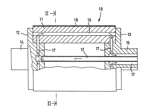
In Figs. 1 and 2, a roll is denoted generally with the
reference numeral 10. The roll 10 comprises a roll mantle 11,
and roll ends 12, 13 attached to both ends of the roll 10. Roll
ends 12, 13 are prov~ded with axle journals 14, 15. The roll 10
of this embodiment is a so-called "drilled roll" in which the
roll mantle 11 is provided with bores 16, or equivalent ducts,
passing from one end of the roll to the other end. A heat
` ` 210862~
tran~fer medium is circulated in these bores or ducts. For this
purpose, the roll lo is provided with the necessary duct sy~ten~
17 for the circulation of the heat transfer medium. In additlon,
a coating i8 is arranged on an outer surface of the roll mantle
11.
In the embodiment shown in Figs. 1 and 2, the bore~ 16
formed into the roll mantle 11 are illustrated. It is preferable
to place the bores as close as possible to the outer face of the
` roll mantle ll.
lo In another embodiment, grooves (not shown) are machined into
~_ the outer face of the roll mantle 11, onto which grooves a
separate mantle (not shown) is arranged. The coating layer 18 i8
arranged on this mantle.
An important feature of the construction and the operation
of the roll 10 in accordance with the invention is that the roll
mantle 11 i9 heated from inside the roll by flowing a heat
tran~fer medium which is passed as close as possible to the roll
face. It is preferable to use hot water or oil or steam as the
heat transfer medium. Since the heating is applied in proximity
to the roll face (via bores 16 or equivalent ducts placed near
the roll face), the thermal resistance of the roll mantle is low,
and a larger amount of heat can be transferred to the roll face
~ with the same temperature difference in the same unit of time.
This produces a limiting factor in the operation and construction
of the roll because a large flow of heat produces a high
temperature difference in the roll mantle 11 which in turn
produces a high thermal stress.
When high temperatures are employed in the roll heating
process, large temperature differences are formed in the roll,
i.e. a considerable temperature profile is formed in the
transverse direction of the machine. This produces a thermal
crown formation in the roll. The bores 16, or equivalent duct~,
- ' ' '
210862~
also produce temperature differences in the roll face in thQ
circumferential direction. ThesQ differences in temperaturQ
further produce local deformations in the roll which unfavorably
affect the operation of the roll in the press section.
In the invention, in order to rsduce the problems described
above, i.e. the drawbacks arising from thermal stresses, ther~al
crown formation, and local deformations, in the invention, the
roll is provided with an insulating coating 18. Owing to the
insulating effect of the coating 18, the temperature differences
are equalized and, as a result, the tensile stres6 and the
thermal deformations in the mantle 11 are reduced. As an
alternative, if it were desirable to keep these factors at the
previous level, the heat flow through the roll face might be
increased.
The following preferences are imposed on the coating 18 of
the roll in the invention to achieve advantageous heat transfer
to the roll face. First, the insulating capacity of the coating
18 must be within certain limits. If the coating material has a
high in~ulating capacity, only a very thin layer is required.
However, generally such materials do not have a good resistance
to wear, and therefore the layer must be thick. Therefore, these
materials are not suitable for use in the invention. As an
~-~ example of such materials, polymers should be mentioned.
On the other hand, if the insulating capacity of the
material is low, a thick layer of the material is needed.
However, a thick layer produces stresses in the roll mantle, so
that such materials are not suitable either. Non-porous, "pure"
metals might be mentioned as an example of such materials.
Besides having a suitable insulating capacity, the coating
layer preferably should have a sufficiently small thickness.
This desired property of a thin coating arises from the fact that
the force with which the coating layer 18 attempts to change the
210862~
form of roll mantle ll is proportional to the thickness of the
coating layer. However, the coating layer must have good
resistance to wear even though it will preferably be relatively
thin. Moreover, the coating layer must have a low modulus of
elasticity which contributes to a reduction in the force~ applied
by the coating layer to the roll mantle ll.
In addition, since one of the functions of the roll lO in a
press section may be to transfer the web, the layer must have
qood web detaching properties when operating both in cold and hot
web transfer operations.
_ These requirements and properties of the insulation coating
layer 18 are most advantageously provided for by a coating made
of a ceramic material, a mixture of ceramic and metal (CERMET) or
a metal containing pores ~a porous metal). The coating is
preferably produced by means of thermal spraying. The thermal
conductivity of such a coating material is substantially lower
than that of the metallic body material of the roll lO. Further,
the modulus of elasticity of such a coating material is lower
than the modulus of elasticity of the roll mantle 11. In the
lnvention, a suitable thickness of the layer of the insulation
material is from about 0.03 mm to about 6 mm, preferably from
about 0.05 mm to about 2 mm.
~~ In a preferred embodiment, the ceramic may be an oxide
ceramic, for example Zr-, Al-, Si-, Ti-, Y-, Cr-oxide or carbide
ceramic, for example Cr-, W-, Ti-, Ni-carbide or a mixture or
aompound of same. With the above ceramics, it is possible to mix
metals, such as Cr, Ni, Co. Preferably, the type of porous metal
metallic coating 18 used in the invention might be e.g. stainless
steel, stellite, bronze, or any other of the metals Ni, Cr, Co,
Fe, Al, Cu or a mixture or mixtures thereof. If the metallic
coating is provided with even a small porosity, typical of
thermally sprayed coatings, the thermal conductivity and modulus
21~862~
of elasticity of the porous metals will be substantially lower.
In porous metallic coatings, for example, the thermal
conductivity may be as low as about 1/5th and the modulu~ o~
elasticity may be as low as about 1/2 of that of co~monly u~ed
structural materials (i.e. cast iron, steel).
In view of providing an insulating effect by means of the
surface layer, it is not advantageous to use a tight, non-porous
and substantially metallic material, because, as was stated
above, to obtain an adequate insulating effect, it would be
necessary to use very thick layers of such a metallic material.
The rigidity of such a thick metallic layer is considerable, the
temperature differences formed in the layer would tend to
increase the thermal deformations in the roll.
In another embodiment, one or more so-called adhesion layers
are provided under the ceramic, metal-ceramic coating or porous
metallic coating, and against the roll body to guarantee good
adhQsion of the ceramic, metal-ceramic layer or porous metallic
layer to the roll body. Corrosion of the material of the roll
body 1~ also prevented in this manner. The adhesion layer is
preferably a thin, thermally sprayed metal layer, which is as
~ free as possible from pores and which does not have a substantial
effect on the thermal conductivity either. In such a case, the
"~ thic~ness of the ceramic, metal-ceramic coating or porous
metallic coating is from about 0.03 mm to about 6 mm, preferably
from about 0.05 mm to about 2 mm.
At least a part of the pores in the coating 18 may be filled
with a sealing material, preferably polymers. Alternatively, all
~` of the pores may be filled with polymers. Polymers which might
be used to fill the pores include epoxy resins, phenolic resins,
polytetrafluoethylene (PTFE) or other equivalent materials which
have good thermal insulation properties and a low modulus of
elasticity. These are advantageous properties for the material
11 ' ,
. " . ,,, " ,
` 2108624
to fill the pores of the coating. Such materials al80 have an
advantageous effect on the detachinq properties of the web.
The porosity of the ceramic, metal-ceramic or porous
metallic coating layer 18 is æelected so that good web detaching
properties are obtained both with and without heating. When the
web runs along the roll, water passes from it into the pores of
the roll. In particular, at high temperatures, the vapor
pressure of the water present in the pores rises and the adheQion
of the web to the roll is lowered. Owing to the insulating
properties of the coating 18, the tendency of the thermal crown
formation in the roll is substantially reduced. Also, the
coating provides a substantial equalization of the temperature
variations especially in the heat transfer medium that runs in a
_.~
drilled roll. For this reason, the ducts or bores 16 may be
lS placed as less densely spaced or, alternatively, be placed closer
the outer face of the roll.
Another advantage of a ceramic, metal-ceramic or porous
mQtallic coating 18 is the suitable heat delivery rate to prevent
burning onto thQ paper. The heat delivery rate is substantially
slowQr on a face of a ceramic, metal-ceramic or porous metallic
¢oating than on a ~ace made of a non-porous metallic coating.
Referring to Figs. 3 and 4, the advantages obtained by means
~_ of the invention as compared with prior art rolls are
lllustrated. Fig. 3 shows a prior art roll without an insulation
as coating layer, whereas Fig. 4 shows a roll in accordance with the
invQntion provided with a coating layer. With regard to the
~ymbols used in Figs. 3 and 4, it should be stated for the saXe
of clarity that, in Fig. 3, ~T refers to the reduction in
temperature in the roll mantle, and, in Fig. 4, ~Tt refers to the
reduction in temperature in the roll mantle, and ~T2 refers to
reduction in temperature in the insulation coating layer.
~` ` 210862~
Fig. 3 shows the transfer of heat in a roll mantle 11' from
a transfer duct 16' into a face 18'. In the following, the
situation in respect of the ducts 16' will be examinQd. In the
area of the roll mantle between the ducts, the situation ls, in
principle, equal. The heat flow ~ that passes through the mantle
11' is proportional to the difference in temperature dT, to the
distance dx across which the difference in temperature is
effective, and to the thermal conductivity a and area A through
which the heat flows. Thus, the equation for the heat flow is:
~ = -a A dT
dx
In Fig. 3, the difference in temperature and the
distribution of temperature are indicated, the distribution being
~ linear in the roll mantle 11'. The thermal stress o produced on
lS the roll face 18' is proportional to the tharmal conductivity ~,
to thQ modulus of elasticity E, and to the difference in
temperat~ure dT. Thus, the equation for the thermal stress is:
o = a E dT
The force F' that produces deformations, per unit of length
t, is stress (average stress a is half the stress at the surface)
time~ distance from the duct to the surface. The equation for
strQss is:
F - 1/2 X o = 1/2 X . a . E dT
~_ t
as
Fig. 4 shows the same reduction in temperature achieved by
adding the insulation layer 18 to the roll face while placing the
heat transfer duct 16 closer to the roll face. Also, the force F
that deforms the mantle 11 has been reduced substantially. The
f`orce arising from the insulation 18 is disregarded because the
modulus of elasticity of the insulation coating layer is
typically only from about 10% to about 30% of the modulus of
Qlasticity of the roll mantle, and the thickness of the coating
layer is small.
210862~
In the embodiments illustrated in Figs. 5 and 6, a roll 10
a8 shown in Figs. 1 and 2 may also be equipped with
variable-crown means to form a variable-crown roll. In thls
embodiment, the roll mantle 11 is arranged to revolve around a
stationary axle of the roll, and the necessary crown varlation
means are arranged between the roll axle and the roll mantle 11.
In Fig. 5, a roll in accordance with the lnvention i8
denoted qenerally with the reference numeral 30. The roll 30
comprises a roll mantle 32, and roll ends 39 attached to both
ends of the roll 30. The roll ends 39 revolve with the roll
mantle 32 about a stationary roll axle 31. The roll 30 is
provided with bores 38, or equivalent ducts, passing from one end
of the roll to the other end.
A heat transfer medium is circulated in these bores or
ducts. For this purpose, the roll end 39 is provided with an
axial bore or duct 40 through which the medium flows. The medium
flows from the axial bore 40 to a radial bore 41, then through
annular grooves 42 formed in the roll 39 to radial bore 43 which
open through a face of the roll axle 31. The annular grooves 42
ao open radially towards the roll axle 31. Radial bore 43 connects
`` the annular grooves 42 to axial bores 44. Axial bores 44
correspond to the amount of bores 38 in the roll mantle and
rQferably align therewith. Annular seals 45,46 are provided
between roll axle 31 and the roll end 39. In addition, a coating
as 37 i8 arranged on an outer surface of the roll mantle 32. The
roll mantle is also provided with end bearings 33.
A~ illustrated in Fig. 5, the roll is provided with crown-
variation means 34 (hydraulic loading means). The hydraulic
loading means 34 are arranged in cylindrical bores 35 and are
regulated by hydraulic pressure. A glide shoe 36 contacts an
inner face of the roll mantle 32 by means of a hydraulic fluld
: 14
. ~ 210~62~
film. Hydraulic fluid is supplied to the crown variation ~ean~
34 via hydraulic pressure fluid supply duct~ 47.
In Fig. 6, another embodiment of a roll in accordance with
the invention is illustrated and denoted generally wlth the
reference numeral 130. The roll 130 comprises a roll mantle 132,
and roll ends 139 attached to both ends of the roll 130. The
roll ends 139 revolve with the roll mantle 132 about a stationary
roll axle 131. The roll 130 is provided with bores 138, or
equivalent ducts, passing from one end of the roll to the other
end. A heat trans~er medium is circulated in these bores or
~- ducts. In addition, a coating 137 is arranged on an outer
surface of the roll mantle 132. The roll mantle is also provided
with an end bearings 133.
A body 140 is attached to the stationary roll axle 131. An
lS annular groove 142 which opens axially towards the roll 130 i~
arranged in the body 140. The medium flows from a heat transfer
medium supply hose or pipe 148 through a bore 141 into the
annular groove 142. From the annular groove 142, the medium
flows through axial bores 144 formed in the roll end 139 to the
bores in the roll mantle 138. Axial bores 144 correspond to the
amount of bores 138 in the roll mantle and preferably align
therewith. Annular seals 145 are arranged between roll axle 131
~ and the roll end 139 and annular seals 146 are arranged between
the roll end 139 and the body 140 attached to the stationary roll
as axle 131.
As illustrated in Fig. 6, the roll is provided with crown-
variation means 134 thydraulic loading means). The hydraulic
loading means 134 are arranged in cylindrical bores 135 and are
regulated by hydraulic pressure. A glide shoe 136 contacts an
inner face of the roll mantle 132 by means of a hydraulic fluid
~`~ film. Hydraulic fluid is supplied to the crown variation means
134 via hydraulic pressure fluid supply ducts 147.
210862~
In the embodiments illustrated ln Figs. S and 6, the heat
transfer medium flows into the roll 30,130 through one ot lts
ends (e.g. as illustrated in Figs. S and 6) and 1~ removed tro~
the roll through its other end ~not shown). The other end is
similar to the first end, however, the fluid flow i~ ln an
opposite direction.
The examples provided above are not meant to be exclusive.
Many other variations of the present invention would be obvious
to those skilled in the art, and are contemplated to be within
the scope of the appended claims.
16
,