Note: Descriptions are shown in the official language in which they were submitted.
0~32
SUCTION CAT~IETER ASSEMBLTES
:~ Back~round of the Invention
. :~
;-~ This invention relates to suction catheter assemblies.
,.-,~
~ 3
`, '~
- . The invention is more particularly concerned with assemblies of the kind having an
:, aspirating catheter enclosed within a protective, flexible sleeve and which can be advanced
. j
. :. through a coupling at one end of the assembly. The coupling has one port connected to a
. tracheal tube and two further side ports by which ventilation of the patient can take place. In
use, the machine end of the catheter is connected to a suction source via a valve. Secretions
; i . .
. that build up on the inside of the tracheal tube, the trachea and bronchi can be periodically
.i removed by opening the valve and advancing the catheter through the coupling and down the
tracheal tube. The coupling enables ventilation of the patient to continue while suctioning
;~ takes place.
:.~
One problem with this kind of assembly is that air may enter the sleeve causing it to
~ inflate which can make subsequent use of the assembly more difficult. A small amount of air
i~ l will be present in the sleeve as a result of assembly and additional air can be pulled into the
sleeve during the negative pressure cycle of sterilization. Air from the ventilation system, during
` . use, can also be forced back into the sleeve. Although a sliding seal can be provided in the
..,1
~1 coupling with the outside of the catheter, this does not provide a total air seal. Attempts to
- improve the seal by making it a tighter fit tend to cause an indentation in the catheter,
`~; especially when it is stored for prolonged periods or subjected to elevated temperature, such as
during sterilization. One way of preventing the accumulation of air in the sleeve is to provide a
small vent that allows air to escape to atmosphere. This, however, is not desirable because it
' can allow the escape of contaminated material from the assembly onto the user.
. ~
:,,
.,
,
.
. ~ , . . .. .
. ~ . ,, ,:, , . : - .. .. : . . ..... ..
-2~ 2 ~L n ~ 3 ~
Exalnples of caeheter assemblies having an aspirating catheter which is contained
within a sleeve and which can be pushed through a sliding seal on a coupling are described in
several patents, such as US 3,991,752 to Radford; US 4,569,344 to Palmer; US 4,638,539 to
Palmer; US 4,696,296 to Palmer; US 4,825,859 to Lambert; US 4,834,726 lo Lambert; US
4,836,199 to Palmer; US 4,838,255 to Lambert; US 4,872,579 to Palmer; US 4,938,741 to
Lambert; US 4,967,743 to Lambert; US 4,981,466 to Lambert; US 5,025,806 to Palmer; US
S,029,580 to Radford; US 5,060,646 to Page; US 5,065,754 to Jensen; US 5,073,164 to
Hollister; and GB 2207736 to Hollister. Suction catheter assemblies ofthis kind are also
available from Smiths Industries Medical Systems Inc under the trade mark STERICATH and
from Ballard Medical Products Inc under the trade mark TRACHCARE.
i
- Summarv of the Invention
,
It is an object of the present invention to provide a suction catheter assembly in
which there is a reduced risk of inflation of the sleeve and in which the user is protected from
3 contact with contaminated material.
~ 1
., According to one aspect of the present invention there is provided a suction
~ catheter assembly for use in removing undesirable fluid from a patient, the catheter assembly
.i comprising: an aspirating catheter having a proximal end and a distal end, said distal end being
suitable for insertion into a patient; a vacuum connecting member located in the vicinity of the
proximal end of the aspirating catheter; a patient connecting member mounted to surround the
aspirabng catheter in the vicinity of the distal end of the aspirating catheter, the patient
~` connecting member having a sliding seal with the outside of the aspirating catheter; a protective
.,
; sleeve surrounding at least the majority of the length of the catheter and extending between the
~` vacuum connecting member and the patient connecting member, the protective sleeve being
` adapted to permit the distal end of the catheter to be extended from the protective sleeve into
the patient and to be withdrawn from the patient; and one way valve means within the patient
connecting member, the one-way valve means permitting gas flow through it out of the
,. .
,., :
.'3 .3 2
-3 -
intel ior of the sl~cvc an(l into tlle patient connecting member but preventing any substantial gas
flow through the valve member into the sleeve such that any gas trapped in the sleeve can
escape into the patient connecting member through the one-way means.
The one-way valve means may take various different forms. In one form, the
. , valve means is a duck-bill valve. The patient connecting member may include a main passage
~ ' through which the aspirating catheter is advanced and a by-pass channel, the one-way valve
-~ . being located in the by-pass channel. The by-pass channel may be substantially parallel with the
main passage and may communicate with the main passage at one end at a location facing the
' sleeve and the rear ofthe sliding seal and at the other end at a location facing the front ofthe
~:- sliding seal. Alternatively, the sliding seal and one-way valve means may be provided by a
1. resilient tubular member having a flange at its proximal end and an internal wiper seal with the
.. catheter at its distal end, the flange having a proximal surface and a distal surface, the assembly
;., including a shoulder that faces distally of the assembly, the proximal surface of the flange Iying
; ~ ~ against the shoulder and the distal surface of the flange being exposed to gas pressure in the
`: ~
`~, patient connecting member distally of the one-way valve means such that the flange is forced
into closer contact with the shoulder by gas pressure on the distal side of the one-way valve
` ~ means and is lifted away from the shoulder by gas pressure on the proximal side of the one-way
valve means.
~.~, ''j'
"."~
.' Alternatively, the one-way valve means may have a disc with a central aperture
through which the catheter extends and makes a sliding seal. The disc preferably has at least
one peripheral aperture therethrough, and a displaceable member such as a flexible diaphragm
which overlies a distal face of the disc in the region of said peripheral aperture such that gas
' pressure on the proximal side of the disc is effective to displace the diaphragm away from the
~` peripheral aperture so as to allow gas flow through the peripheral aperture.
i.,
i In another form of assembly, the one-way valve means may include a porous disc
-~ with an aperture through which the catheter extends, and a flexible diaphragm which overlies
, .
3 '' 2
a distnl filcc of tllc di~c sucll tl1llt ~a~ prcssure on the pro~imal side of the disc is efFective to
displace a part of the diaphragm away from the disc so as to allow gas flow therethrough, and
such that gas pressure on the distal side of the disc is effective to urge the diaphragm against
the disc and prevent any substantial gas flow therethrough.
The patient connecting member preferably includes a patient end coupling alignedwith the aspirating catheter, the patient end coupling being adapted to be coupled with a
tracheal tube, the patient end coupling having two side ports which communicate with the
interior of the patient end coupling on the distal side of the one-way valve means, and the two
side ports being adapted for connection to ventilation apparatus such that the patient can be
aspirated without interruption of ventilation. The vacuum connecting rnember may include a
manually-operable valve, the manually-operable valve normally blocking fluid flow along the
aspirating catheter but can be manually opened to permit fluid flow along the catheter
....
::; According to another aspect of the present invention there is provided a method
.
of suctioning undesirable fluid from a patient in which the patient cormecting member on the
.,
,. assembly is connected to a tracheal tube and the vacuum connecting member is connected to a
,,
suction source. The patient is ventilated via the patient connecting member such that the one-
` way valve means prevents any substantial gas flow into the sleeve and the aspirating catheter is
j . ,j
advanced through the sliding seal so as to aspirate the patient without intersuption of
ventilation and such that the one-way valve means allows any trapped air in the sleeve to be
forced into the patient connecting member as the aspirating catheter is advanced.
' Subsequently, the aspirating catheter is withdrawn through the sliding seal.
, j -
,,~
Several suction catheter assemblies according to the present invention, will now
` ~ be described, by way of example, with reference to the accompanying drawings.
., .
',''';
: . -` 2 ll)89~2
--5--
icrl)cscril~tion ofthc Dr~lwilll~s
`
:
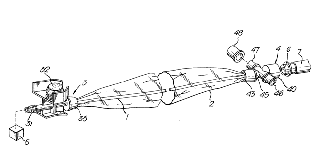
: ~ . Figure 1 is a perspective view of the assembly;
'`
Figure 2 is a sectional side elevation of the patient
. connecting member;
,
Figure 3 is a transverse section along the line III-III of
Figure 2;
,
Figures 4 are sectional views of an alternative patient
and 5 connecting member;
Figures 6 are enlarged sectional views of alternative
to 8 valves;
. .,
A
.~ Figure 9 is a transverse section along the line IX - IX
.
of Figure 8;
.: :
;-.~',
Figure 10 is an exploded, perspective view of still
: another embodiment of the patient connecting
` member; and
.
Figure 11 is a transverse section taken along the line
XI-XI of Figure 10.
.
,.
.,.
2 1 ()~
--6--
:Dcscril)tioll Ortllc rrcrellell Embodiments
With reference first to Figures 1 to 3, the suction catheter assembly comprises an
aspirating catheter 1 that extends within a flexible, protective sleeve 2 between a vacuum
connecting member 3 and a patient connecting member 4.
~ '
. The aspirating catheter 1 is of conventional construction having an outside
~; diameter of about 4-5mm and a length of about 55cm. In the illustrated example, the catheter
1 has a single lumen 10 although catheters with multiple lumens for use in irrigation and/or
. oxygen supply could be used. At its machine or proximal end, the catheter 1 is secured to the
.. ~ vacuum connecting member 3.
~ . .
The vacuum connecting member 3 is moulded from a rigid plastics material and
" has a bore (not shown) extending along it into one end of which the catheter 1 is bonded. The
` ~ opposite end of the bore extends through a spigot 31, which, in use, is connected to tubing (not
shown) extending to a vacuum or suction source 5. The vacuum connecting member 3 includes
. a conventional manually-operated valve 32, which norrnally prevents flow through the
i:,
,~ connecting member 3 and catheter 1 but which can be pressed down by the user to open the
valve and connect the lumen 10 of the catheter to the suction source 5.
:
. . .
~ The proximal end of the sleeve 2 is secured to the vacuum connecting member 3
: .. beneath a collar 33 secured to the distal end of the vacuum connecting member. The distal end
'. b. of the sleeve 2 is similarly secured to the patient connecting member 4 by means of a collar 43
: which is secured on a proximal extension piece 44 that is in turn joined to the main body 45 of
;.' the patient connecting member.
,,~ , ~,
The patient connecting member 4 is of generally cruciform shape, having a female
luer coupling 40 at its distal or patient end, which is aligned with the ax;s of the connecting
..,
,
., ~
2 tO~2
--7--
lnclllber an(l witll tlle proximal extension 44. '['he coupling 40 is adapted to be connected to a
cooperating coupling (not shown) on the end of a tracheal tube. Two side ports 46 and 47
extend at right angles to the axis of the connecting member, directly opposite one another,
about midway along the length of the coMecting member. These two side ports 46 and 47
communicate directly with the interior of the coupling 40 and are used in the conventional
manner to coMect with ventilation apparatus. One port may be used for inhalation gas and
the other port used for exhalation gas. Alternatively, one of the ports 47 may be closed by a
cap 48 and inhalation and exhalation both be effected through the other port 46.
Within the patient connecting member 4 there is a novel sealing device and one-
way valve 50. This takes the form of a resilient, generally tubular member having a flexible,
external, aMular flange 51 at its proximal end that is trapped between the main body 45 and a
shoulder 49 in the proximal extension piece 44. The shoulder 49 faces distally of the assembly
and is contacted by the proximal surface of the flange 51. The proximal end of the main body
45 has one or more cut-away portions 55 so that the flange 51 can be lifted away from the
shoulder 49, into these portions, by elevated gas pressure on the proximal side of the flange. At
its distal end, the valve 50 has an internally-extending wiper seal 52 defining a circular aperture
53 through which the catheter 1 extends and to which a sliding seal is formed. Externally, the
valve 50 has a shallow taper of about 2-3, so that it has a smaller diameter at its distal end.
The distal surface of the flange 51 is exposed to gas pressure on the distal side of the valve by
means of the cut-away portions 55 and passages 54 formed around the inside of the proximal
end of the main body 45 of the patient connecting member. Internally, the valve 50 has a
steeper taper of about 13-14 so that it has a smaller internal diameter and a greater wall
thickness at its distal end. The interior of the valve 50 is exposed to gas pressure on the
proximal side of the valve.
"^,'
:i
~ In operation, the coupling 40 of the coMecting member 4 is secured to a
; coupling 6 on the end of a tracheal tube 7 and its side ports 46 and 47 are connected to a
: ventilator. The vacuum coupling member 3 is connected to the suction source 5 but, as long as
~',
., ~,, ,
,. .: ~ ,;. . :
2~ ~)8~32
-3 -
thc Ill~lllllnl V-IIVC 32 ICltl-lillS UrlllCt~latC~, no suction is applied to the catheter 1. While
mechallical vetltilation takes place, there is raised, positive pressure within the patient
connecting member 4 (on the distal side of the valve 50) which forces the distal side of the
flange 51 against the shoulder 49, thereby improving the seal of the flange on the shoulder and
.
blocking gas flow into the sleeve 2.
When aspiration of fluid from the trachea or bronchi is required, the user grips the
catheter 1 through the sleeve 2 and pushes it forwardly so that the distal, patient end of the
catheter is advanced through the connecting member 4 and into the tracheal tube 7. When the
catheter 1 has been inserted to the desired depth, the wser depresses the valve 32 so that the
catheter is connected to the suction source 5 and fluid in the vicinity of the tip of the catheter is
sucked into the catheter and removed. During aspiration, ventilation of the patient occurs
normally. When aspiration is complete, the catheter 1 is pulled back into the sleeve 2, the
assembly remaining attached to the tracheal tube connector 6 so that it can be reused when
.
~I necessary.
. . .
, Although the sliding seal of the valve 50 with the catheter 1 is effective to prevent
any significant flow of gas into the sleeve 2, there may be some seepage of gas around the
., catheter, especially when the catheter is being manipulated during aspiration. The valve 50 is,
', however, effective to allow any gas trapped inside the sleeve 2 to escape when pressure on its
' proximal side exceeds that on the distal side. The action of gripping the sleeve 2 and advancing
;, the catheter 1 has the effect of compressing any trapped gas in the sleeve, thereby increasing its
.. pressure and allowing it to open the valve by forcing the flange 51 away from the shoulder 49
'`I
in the cut-away portions 55. The valve 50, therefore, acts as a one-way valve, allowing flow
'` only distally of the valve. In this way, build-up of gas in the sleeve 2 is prevented since the
sleeve 2 can vent at relatively low pressure. Because the venting occurs into the connecting
member 4, the vented gas is carried to the ventilation system without any risk of cross
contamination to the clinician.
: ,.
..,~
,
~ .
~9.- 210~932
Various modifications are possible to the embodiment described. For example,
the valve could be of the form shown in Figures 4 and 5. In this arrangement, the sealing device
and one-way valve 60 takes the form of a disc 61 of a stiff but resilient material, such as a
plastics, which is about 5mm thick and is bonded to the inside of the connecting member wit'nin
the proximal extension 44 or at some other point proximally of the ventilation side ports 46 and
47. The disc 61 has a circular central aperture 62 which is a close sliding fit about the outside
of the catheter 1 so as to form a sliding seal with its surface. The disc 61 is also provided with
several smaller peripheral apertures 63 which extend through its thickness. The sealing device
60 is completed by a displaceable member in the form of a thin annular diaphragm 64 of a
flexible gas-impervious plastics material. The diaphragm 64 is slightly smaller in external
diameter than the disc 61 and has a central aperture that is slightly larger than the aperture 62
of the disc. The diaphragm 64 is bonded, such as by welding, solvent or adhesive, around its
central aperture to the distal face of the disc 61 to form an annular bond 65. Outwardly of this
bond 65, the diaphragm 64 overlies the peripheral apertures 63 and is unattached to the disc 61.
The nature of the diaphragm 64 is such that it will remain flat against the surface of the disc
for any orientation of the assembly but it can be deflected readily away from the disc by
positive gas pressure through the apertures 63.
The one-way valve 50 or 60 could be provided in one part of a patient connectingmember, with the side ports 46 and 47 and the ~emale luer coupling 40 being provided in a
separate part that is coupled together with the first part during use.
The one-way valve and the sliding seal with the catheter could be formed by
separate components, as shown in Figure 6. In this arrangement, the sliding seal with the
, 1
catheter 1' is provided by a gasket 70 secured to one side of a rigid valve disc 71. The valve
-;i disc 71 is similar to the disc 61 but has a larger central aperture 72 to allow freer movement of
the catheter. A diaphragm 74 covers peripheral apertures 73 through the disc and seals them
closed in the same way as described above.
~o 2:1 08~32
-
Another modification is shown in Figure 7. In this, a disc 81 is made from a
material that is porous through its thickness. A non-porous film 82 may be provided through a
. -.' central aperture 83 to form an effective sliding seal with the catheter 1 ". A flexible annular
J
.: diaphragm 84 is attached only around its inner edge to the distal face of the disc 81 so that gas
can flow through the disc in the distal direction but is impeded in a proximal direction.
.
:~ In the arrangement shown in Figures 8 and 9, a diaphragm 94 acts as both a valve
member and as a sliding seal with the catheter 1"'. The diaphragm 94 has a central aperture 95
.; that is a sliding seal with the outside of the catheter, the diaphragm being supported centrally by
a skeletal support 96 that is secured to the housing of the patient connecting member 4 by
. means of radially extending arms 98. An internal annular step 99 is formed around the inside of
. the housing, the step facing distally of the assembly and the outer peripheral region of the
diaphragm 94 being seated on this step. The edge of the diaphragm 94 is deforrned away from
the step 99 by pressure from within the sleeve but, in normal use, the pressure from the
- i respiration system forces the edge of the diaphragm in a proximal direction, more firmly against
~1 the step so that air can only flow in one direction.
. 1
Figures 10 and 11 show another modification of the patient connecting member 4'. The
housing of the patient connecting member 4' includes a small by-pass channel 104 in addition to
a main passage 103 through which the aspiration catheter is advanced. A stationary sliding seal
or wiperlseal member 101 is provided in the main passage 103 sealingly engaging the outer
surface of the aspirating catheter 1. A one-way, V-shape check valve, such as a duck-bill valve
102 is mounted in the patient connecting member 4' to allow passage of entrapped air from the
protective sleeve 3 into the patient connecting member 4'. The one-way valve 102 is located in
the by-pass channel 104 so that air from the sleeve flows along a path defined by the by-pass
channel 104 and into the patient connecting member 4'. The by-pass channel 104 is formed
between the outer wall of the housing (main body 45 and extension 44) and an inner wall 105
substantially surrounding the seal 101 and coaxial with the outer wall ofthe housing. As shown
' .
210~9.32
in Figure l l, the one-way valve 102 positioned in the by-pass channel 104 is substantially
parallel with the wiper/seal 101. The rear ends 106 and 107 ofthe wiper seal 101 and the one-
way valve 102 respectively are substantially aligned with each other. The by-pass channel 104
comrnunicates with the main passage 103 at one end at the location facing the rear end 106 of
the wiper/seal member 101 and at the other end at the location facing the front end 108 ofthe
wiper/seal.
In operation, advancing the catheter 1 into the patient compresses the protective sleeve
3. This compression pressurizes the air inside the sleeve caush1g the one-way valve 102 to
open and allow air to flow out of the sleeve into the T-piece and ventilation circuit. A certain
amount of residual air will remain in the sleeve at atmospheric pressure so that the sleeve does
not cling to the catheter when it is withdrawn from the patient. This is an important advantage
over prior valves and facilitates manoeuvring of the catheter. The one-way valve prevents air
from the ventilator entering the sleeve, thereby reducing the risk that the sleeve will be inflated.
.,,
,i,
:"1
!`..,
.~
.
. i 'i~ .
.t
','i' .~ '