Note: Descriptions are shown in the official language in which they were submitted.
WO92/19335 PC~/GB92/0~7X~
21~8973
. . --1--
"Ground Cover"
This invention relates to a ground cover, for
example (but not exclusively) one which can be used to
protect the grass of sports fields.
A number of air supported structures have been
- used in the past or protection of sports fields in
connection with a variety of different sports.
These have included covers for cricket squares,
tennis courts and football pitches. However, in many
cases, the ground covers are somewhat cumbersome and
easily fall into a state of disrepair. In addition,
7' ' ground covers presently available tend to be relatively
I expensive, especially since many require permanent
'r foundations.
1~ 15 Other covers require a large underground trench,
i preferably with an artificial grass cover, to store the
ground cover when it is not in use. In addition,
permanent anchor points for securing the erected cover to
the ground are often required.
Other forms of ground cover presently available
are simple plastic sheets laid on the ground and rolled up
to one side of the ground to be protected when not in use.
These have the disadvantage that they do not throw
rainwater clear, and they also cannot be used for
extensive periods since they are likely to cause grass
disease.
The present invention attempts to overcome these
problems since it does not require e~tensive permanen_
i; : ~ '
, .
, .
i
WO92/1933~ pcr/G~2/~u1~
. . .
21Q8~ 2- ~
securing means, can be easily stored, is relatively
inexpensive and, in certain of its arrangements, is less
likely to cause grass disease when in use.
According to the present invention, there is
5 provided a ground cover comprising:
a main sheet; and
means for creating a sub-atmospheric pressure
beneath the sheet.
Preferably, the sheet is hollow and divided into
10 zones, and there is also provided means for creating a
super-atmospheric pressure in the hollow zones wlthin the
sheet.
The majority of the ground cover can be formed
of a robust plastics material, but other robust materials
15 could also be used.
The ground cover can have any desired shape, but
conveniently is rectangular, for example square.
The main sheet is preferably in the form of a
~ plurality of zones or compartments in the form of inflated
3 20 tubes joined to each other. A positive pressure is
maintained in these tubes whilst the ground cover is in
use, for example by means of an attached fan pumping air
i into the tubes. Each tube may be joined to an adjacent
i~
tube by seams which may act as gutters on the outside of
j` 25 the sheet for rainwater, or the like. Preferably, the
~; tubes taper and become smaller in height from one end to
? the other such that rainwater may travel along the seams
which act as gutters from the larger end ~o tne smaller
... .
.;, .
., . ,~
:,. . . . . . ..... ..
, ' . , , , '
WO92/19335 PCT/GB92/007X~
210~73
-3-
end of the tubes to a collection point, from where it may
be pumped away from the surface to be protected.
The tubes may be in any position relative to
each other but are preferably parallel.
The walls between the tubes may be solid, in
which case each is inflated by passage of air around the
perimeter of the cover into each tube separately, or may,
for example, comprise netting thus allowing passage of air
; between the walls of adjacent tubes. If the walls between
the tubes are solid, passage of air may be allowed into
either end or both ends of the tubes.
Underneath the ground cover there is provided a
reduced air pressure, which draws the cover downwardly
towards the ground, thus opposing wind forces which may
tend to lift the cover due to the "vacuum effect" induced
by the movement of the wind at speed ove- the upper
surface of the cover, and also due to the wind getting
under the edge of the cover and then lifting it.
In preferred embodiments of the cover of the
present invention, the likelihood of grass disease is
reduced due to the passage of air under the region of the
seams between adjacent tubes making up the ground cover.
In particularly windy conditions the fan speed can be
adjusted to increase the sub-atmospheric pressure beneath
the ground cover and therefore to increase the downward
force. The fan speeds may also be adjusted in order to
ease the movement of the cover from one part of a surface
to be protected to another part of tha. surrace.
~ .,
, ,
. . .
WO92/19335 PCT/GB92/0~7~4
~8973 -4-
The air pumped into the tubes may be warm in
order to protect the ground from the cold due to frosty or
snowy conditions, and to melt snow for removal. The
introduction of warm air may enhance growing conditions
under the cover, which could preferably be further
improved by the secondary infiltration of warm air through
perforations in any or all of the tubes, preferably only
the outermost tubes, or similar means, to the underside of
the cover which is at sub-atmospheric pressure.
lOIn addition, a simple guy rope and peg system
may be provided as emergency backup in the event of power
failure.
:
`~ Although a wide variety of shapes and sizes of
cover can be manufactured and used, very large areas may
,15 be protected by joining two or more ground covers to each
,other in order achieve the desired degree of protection.
By way of example, the typical size of a single cover may
;be 22m x 44m and is suitable for covering, for example,
.the main area of wear on football pitches, that is the
¦20 penalty area or centre circle.
Preferably, the super-atmospheric pressure for
the inflation of the tubes is of the order of lS00 Pa
gauge, and the sub-atmospheric pressure used beneath the
ground cover is of the order of -356 Pa gauge.
25When not in use, the ground cover is deflated
and, for convenience, a trailer can be provided, which can
, support the fan unit and the deflated cover for easy
-~ storage.
',~
, .
s
.,
~. .
. .
.,~, , : .
. .
. ..... .
WO92/1933~ PCT/GB92/~X4
,, ,"".~, 21~897~
For a better understanding of the present
invention, and to show how the same may be carried into
effect, a preferred embodiment of the invention will now
be described, by way of example, with reference to the
S accompanying drawings, in which:
. Figure l is a plan view OI the cover;
. Figures 2 and 5 are respectively side views in
the directions of the arrows II-II and V-V in Figure l;
and
Figures 3, 4, 6 and 7 are respectively cross-
; sections taken along the lines III-III, IV-I~', VI-~'I and
VII-VII in Figure 1.
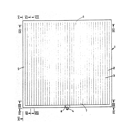
~Referring firstly to Figure 1, the cover
.3~.includes a plurality of tubes 2 joined together along
.15 seams 3 and having open ends 6 and partially closed ends
~,7, the ends 7 having end walls which are perforated and
are formed of netting, for example. In use, air is pumped
into the cover 1 through an inflation inlet 4 and then
passes around a peripheral distributing tube ~ of the
~20 cover entering the tubes 2 at both their partially closed
'J.ends 7 and their open ends 6. The air is pumped into the
cover 1 until the desired degree of inflation is achieved.
. "
.,In the embodiment shown in Figure 1, the ends ç
~of the tubes 2 are greater in hei~ht than the ends 7 of
;:25 the tubes 2, and, as a result, there is a slope from the
;3ends 6 to the ends 7 down which rainwater or the like may
fall. There may additionally be a gutter in the vicinity
of the ends 7 of the tubes which ccllects the rainwater
. .
`i .
;!
.' ~
~; ' ,
,
;`' ' ,
W092/19335 PCT/GB92/0~784
' .
2 1 Q 89 7 3 -6-
and from which the water can be pumped away.
A sub-atmospheric pressure is achieved beneath
the cover 1 by extracting air through an outlet 8. The
resulting reduced air pressure draws the cover 1 onto the
ground, thus opposing wind forces which may lift the cover
due to the "vacuum effect" induced by the movement of the
wind at speed over the upper surface of the cover, and
also due to the wind getting under the edge of the cover
and then lifting it. The presence of the seams 3, as well
as the provision of inflatable projections lO (see Figure
6) on the bottoms of the tubes 2, means that the area of
the underside of the cover in contact with the ground is
relatively small, and thi.s, in combination with the
. passage of air under the cover, reduces the likelihood of
,15 significant grass disease.
As may be seen in the view of the cover taken at
the inlet/outlet end shown in Figure 2, as hell as in the
side view of Figure 5, the distributing tube 5 is itself
.provided with an inflatable lower rib ll extending about
the periphery.
The cross-sectional view in Figure 6 shows the
slope of the tubes 2 from the larger ends 6 of the tubes
to the smaller ends 7 of the tubes, whereas the cross-
sectional view in Figure 7 shows the joining walls 9 at
the seams 3 between the tubes 2.
-Referring now to Figure ~, the cross-sectional
view at the larger ends 6 of the tubes 2 is shown in which
~,the seams 3 are formed by the joining walls c between the
.5
~,,
~,',' ' ~: '
(' , :
r' ~ ' , : , ,
:
WO92/19335 PCT/GB92/~07X~
2~0897~
-7-
tubes. ~he walls 9 may be solid, in which case the tubes
2 are inflated by passage of air into one or both ends of
the tubes, or may comprise netting thus allowing passage
of air between adjacent tubes.
Referring now to Figure 3, the cross-sectional
view at the smaller ends 7 of the tubes 2 is shown. In
this embodiment, the area of contact between adjacent
; tubes is small at the ends 7. Thus, the area of contactbetween adjacent tubes tapers from a r,aximum at the larger
ends 6 of the tubes to a minimum at the smaller ends 7 of
the tubes.
~ '
;i
.. ..
., .
.
: .
.
,, ~ ' ' .
. - :