Note: Descriptions are shown in the official language in which they were submitted.
- D-20009
210~038
CRyQ~T'NIC RTi`CTIFI~ATION. SYSTF~
WITH THT~RMAT,T,y INTEC.RATEn ARGDN COLUMN.
Technical Field
This invention relates generally to cryogenic
rectif ication and more particularly to cryogenic
rectif ication employing an argon column .
Backqro~nr7 ,Art
Argon is ~eC~rin~ increasingly more important
for use in many industrial applications such as in the
production of stainless steel, in the electronics
industry, and in reactive metal production such as
titanium processing.
Argon is generally produced by the cryogenic
rectif ication of air. Air contains about 78 percent
nitrogen~, 21 percent oxygen and less than 1 percent
argon. Because the argon concentration in air is
rel2tively low, it has the highest per unit value of
the major ai _~ ^ric gases. However, conventional
cryogenic air separation proces6es can recover only
about 80 to 90 percent of the argon in the feed air.
Thus it is desirable to increase the recovery of argon
produced by the cryogenic rectification of air.
S~lr~~rv of the Invention
The above and other objects which will become
' apparent to one skilled in the art upon a reading of
this disclosure can be attained by the present
invention, one aspect of which i5:
A cryogenic rectification method for
producing argon comprising:
(A) providing a feed comprising argon into a
main column system and carrying out cryogenic
- ~ D-20009
--
2 21~9038
rectification within the main column system;
(B) withdrawing argon-containing vapor from
the main column system and condensing said argon-
containing vapor;
(C) reducing the pressure of the resulting
argon-containing liquid;
(D) proYiding reduced pressure argon-
containing liquid as feed into an argon column at an
intermediate point of the argon column and separating
the feed by cryogenic rectification into argon-richer
fluid and argon-leaner fluid;
tE) withdrawing argon-leaner fluid from the
argon column, increasing its pressure, and passing
increased pL~s~,uL~ argon-leaner fluid into the main
column system; and
(F) recoYering argon-richer fluid as product
argon .
Another aspect of the invention i6:
A cryogenic rectification apparatus for
producing argon comprising:
(A) a main column system and means for
providing feed into the main column system;
(B) an argon column, a condenser and means
for passing fluid from the main column system to the
c~n~l~n- er;
(C) means for passing fluid from the
c~n~l~nc~r into the argon column at an intermediate
point of the argon column;
(D) means for reducing the plesD,,Le of fluid
passed from the condenser into the argon column;
(E) means for withdrawing fluid from the
lower portion of the argon column, means for increasing
the ~L~S~uL~ of the withdrawn fluid, and means for
passing the increased E"es~uL~ withdrawn fluid into the
_
D-20009
3 ~9038
main column system; and
(F) means for recovering fluid taken from
the upper portion of the argon column.
As used herein the terms "upper portion" and
"lower portion" mean those sections of a column
respectively above and below the midpoint of a column.
As used herein the term "feed air" means a
mixture comprising primarily nitrogen, oxygen and
argon, such as air.
As used herein the term "Lu,},oex~ansion"
means the f low of high pressure gas through a turbine
to reduce the pressure and the temperature of the gas
thereby generating refrigeration.
As used herein the term "column", means a
distillation or fractionation column or zone, i.e., a
contacting coluDm or zone wherein liguid and vapor
phases are countercurrently contacted to effect
separation of a fluid mixturef as for example, by
contacting or the vapor and liguid phases on a series
of vertically spaced trays or plates mounted within the
column and/or on packing elements which may be
structured packing and/or random packing elements. For
a further discussion of distillation columns, see the
Chemical Engineers' ~n~lho~k fifth edition, edited by
R. H. Perry and c. H. Chilton, NcGraw-Hill Book
Company, New York, Section 13, The cont~ n~
Distillation Process. The term, double column is used
to mean a higher pressure column having its upper end
in heat exchange relation with the lower end of a lower
p~.,6DULe column. A further discussion of double
columns appears in Ruheman "The Separation of Gases"
Oxford University Press, 194g, Chllpter VII, Commercial
Air Separation.
Vapor and l~quid contacting separation
=
- D-20009
--
4 2109~38
processes depend on the difference in vapor ~Les.uL~:s
for the _ nn~nts. The high vapor ~1~52jUL~ tor more
volatile or low boiling) c ~ r.L will tend to
conce"Ll-te in the vapor phase whereas the low vapor
~es .u. e (or less volatile or high boiling) c ~ ont
will tend to concentrate in the liquid phase. Partial
co~nC2ltion is the separation process whereby cooling
of a vapor mixture can be used to concentrate the
volatile component(s) in the vapor phase and thereby
the less volatile ~ nt(s) in the liquid phase.
Rectification, or continuous distillation, is the
separation process that combines successive partial
vaporizations and condensations as obtained by a
count~ uLLellL treatment of the vapor and liquid
phases. I'he counteL~;u~L~:"~ contacting of the vapor and
liquid phases is adiabatic and can include integral or
differential contact between the phases. Separation
process arrangements that utilize the principles of
rectification to separate mixtures are o~ten
interchangeably termed rectification columns,
distillation columns, or fractionation columns,.
Cryogenic rectification is a rectification process
carried out at least in part at temperatures at or
below 123 degrees ~Celvin.
As used herein the term "indirect heat
exchange" means the bringing of two fluid streams into
heat exchange relation without any physical contact or
intermixing of the f luids with each other .
As used herein the term "argon column" means
a column which processes a feed comprising argon and
produces a product having an argon concentration which
exceeds that of the feed and which may include a heat
exchanger or a top con-l~nc~r in its upper portion.
As used herein the term "equilibrium stage"
- ~ D-20009
_
5 21~9038
means a contact process between vapor and lilauid such
that the eYiting vapor and liguid streams are in
equilibrium .
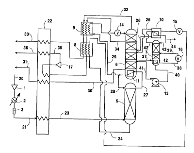
Brief Descri~tion of the Drawinas
The sole Figure is a schematic f low diagram
of one preferred ~"~ho~ t. of the cryogenic
rectification ~ystem of this invention.
Det~ i l ed Descri~tion
In conventional cryogenic rectif ication
practice employing a main column system and an argon
sidearm column, the argon column is generally coupled
to the upper column of a double column system 50 that
they operate at about the same pressure. This
invention includes the partial uncoupling of the argon
column from the main column system so that it may
operate at a lower p~s~u~e than would otherwise be
possible. The lower pres6ure increases the relative
volatilities between argon and the other major
_~ ,onents of the feed undergoing separation in the
argon column thus enabling a greater amount of the
argon fed into the column to be recc,~ere~ and reducing
the amount of argon passed out of the argon column with
the other c Jl~el~ts. The argon column is thermally
integrated with the main column system in a manner
which create6 a small stripping section in the argon
column which reduces the argon content of ~pcc~n~l i n~
liquid within the argon column resulting in a large
increase in argon recovery.
The invention will be described in detail
with reference to the Figure which illustrates the use
of the invention to produce product crude argon from a
feed comprising oYygen, nitrogen and argon, e.g. air,
.
D-2 0009
6 2109038
.
wherein the main column system is a double column.
Referring now to the Figure, feed air is
compressed by passage through ~SSuI 1, cooled by
passage through cooler 2 to remove the heat of
_ : ession, and cleaned of high boiling impurities
such as water vapor, carbon dioxide and hydrocarbons by
passage through purifier 3. Cleaned, cooled,
es~ied feed air 21 is then cooled by passage
through main heat exchanger 22 by indirect heat
exchange with return streams and the resulting cooled
feed air 23 is passed into column 5 which is the higher
pressure column of a double column system which is the
main column system in the practice of this embodiment
of the invention. Column 5 is operating generally
within the range of from 65 to 220 pounds per square
inch absolute (psia).
Within column 5 the f eed air is separated by
cryogenic rectification into oxygen-enriched liquid and
nitrogen-enriched vapor. oxygen-enriched liquid is
withdrawn from the lower portion of column 5 in stream
24, ~ubcooled by passage through heat exchanger 8 by
indirect heat exchange with return streams and then
passed through valve 15 and into argon column top
co~ ncer 10 wherein it ic partially vaporized by
indirect heat ~YrhAn~e with argon-richer vapor as will
be more fully d;.sc-l~s~d later. ~he resulting vapor and
in;n~ liquid are passed from top con~l~nc~r 10 in
streams 25 and 26 respectively into column 6 which is
the lower pressure column of the double column system.
Column 6 is operating at a pressure less than that at
which column 5 is operating and generally within the
range of from 14 . 7 to 75 psia .
~itrogen-enriched vapor is passed from the
upper portion of column 5 in stream 27 into main
D-20009
7 2109038
con~l~nC~r ll wherein it i6 con~ need by indirect heat
exchange with oxygen-rich bottoms of lower ~es~uLc!
column 6. Resulting nitrogen-enriched liquid is passed
as stream 28 into column 5 as reflux. A portion of the
nitrogen-enriched liquid ls passed in stream 29 through
heat ~yrhAnqer 9 wherein it is subcooled by indirect
heat exchange with return 6treams, and passed through
valve 14 and into column 6 as reflux. If de6ired, a
portion of the nitrogen-enriched liquid may be
recovered as product liquid nitrogen.
Within column 6 the feeds are separated by
cryogenic rectification into nitrogen-rich fluid and
oxygen-rich fluid. Oxygen-rich vapor is withdrawn from
the lower portion of column 6 in stream 30, warmed by
passage through main heat exchanger 22 and may be
recovered as product oxygen gas 31. If desired,
oxygen-rich liquid may be withdrawn from column 6 in
the area of main con~ nc~r 11 and recuv~L ed as product
liquid oxygen. Nitrogen-rich vapor is withdrawn from
the upper portion of column 6 in stream 32, warmed by
passage through heat exchangers 9 and 8 and main heat
exchanger 22, and may be recovered as product nitrogen
gas 33.
For product purity control purposes a waste
stream 34 is withdrawn from the upper portion of column
6 below the withdrawal point of stream 32. Stream 34
is warmed by passage through heat exchangers 9 and 8
and partially traverses main heat exchanger 22.
5tream 34 is then expanded through turboexpander 17 to
generate refrigeration and resulting tur~o~An~
~tream 35 is warmed by passage through main heat
~ rhAn7Dr 22 whereby refrigeration is put into the
process by transfer to the feed air. Resulting waste
stre~m 36 is then removed from the system.
- ~ D-20009
--
8 ~I09~38
Refrigeration may be put into the system in other ways
well known to those skilled in the srt such as by
expansion of a portion of the feed air followed by
passage into the lower pressure column, the expansion
of nitrogen from the higher pressure column, the
expansion of a product stream, or the expansion of the
entire feed air 6tream.
A~yc"l containing vapor is withdrawn from the
main column system. In the ~mho~ ?nt illustrated in
the Figure, argon-containing vapor is withdrawn as
stream 37 from column 6 at a point at least one
equilibrium stage above the area of main c~n~l ~n~r ll
where nitrogen-enriched vapor is con~i~n~P~ against
oxygen-rich fluid. Preferably this withdrawal i5 at a
point within the range of from lO to 40 equilibrium
stages above the described heat exchange. The argon-
containing vapor generally comprises from about 5 to 20
mole percent argon with the r~ ; ndPr comprised mostly
of oxygen.
2 0 At least some of the a. ~ col~taining vapor
is passed into latent heat exchanger or c~nrl~nC~r 12
wherein it is condensed. Con~F~n~r 12 may be within
argon column 7 as illustrated in the Figure, or it may
be outside argon column 7. The resulting argon-
containing liquid 38 is reduced in ~Les~,u-e by passage
through valve 16 and the reduced pressure argon-
containing liquid 39 passed as feed into argon column
7. If desired, a portion of the argon-containing vapor
or a second argon-containing vapor stream may be
3 0 reduced in pressure and passed directly into the argon
column as feed without undergoing con~Pn~ation.
The reduced pressure argon-containing liquid
is passed into argon column 7 as feed at an
intermediate point, i . e. above the lowermost
D-20009
9 2las~3s
equilibrium stage and below the ~rr~ equilibrium
stage of argon column 7. Argon column 7 is operating
at a pressure less than that at which column 6 is
operating. Preferably the operating pres6ure of argon
column 7 is at least 3 psi below that of column 6 and
generally is within the range of from 10 to 70 psia.
If desired, the operating pressure of argon column 7 at
least within its upper portion may be below the ambient
pressure . This lower pressure is a ma j or advantage of
the uncoupling of the argon column from the main column
system by virtue of the cond~ncAtion of the argon-
containing vapor in stream 37 at a higher pressure and
the return of pl ~S~ul ized argon-leaner f luid back to
the main column system as will subsequently be
described.
Within argon column 7 the f eed is separated
by cryogenic rectification into argon-richer fluid and
argon-leaner fluid. Preferably the argon-containing
vapor is condensed in c~n~ ~nC-~r 12 by indirect heat
~YrhAn~e with argon-leaner fluid. The argon-leaner
fluid comprises mostly oxygen. Generally the argon-
leaner fluid comprises from about 82 to 97 mole percent
oxygen with the r~-- i n~r being argon . Argon-leaner
fluid is withdrawn from the lower portion of argon
column 7 in stream 40, is increased in pressure such as
by passage through pump 13 and i6 passed as stream 41
into column 6 of the main column system. If the argon
column is at a sufficient elevation relative to the
other columns, the pressure of the argon-leaner fluid
may be increased by liquid head y~sDule thus
eliminating the need for mechanical pump 13. In this
case a mechanical pump may be nF'C~CFAry to pass oxygen-
enriched fluid from column 5 to top con~l~n~r 10.
Argon-richer fluid generally comprises at
D-20009
2109038
.
least 80 mole percent argon. Argon-richer fluid i6
passed as stream 42 from the upper portion of argon
column 7 into con~lPncPr 10 wherein it is cooled by
indirect heat exchange with partially vaporizing
oxygen-enriched liquid. The resulting argon-richer
rluid is passed back into the upper portion of column 7
as stream 43 while a portion 44 of the argon-richer
fluid is recovered as product argon.
The invention ~nh~n~-ec the argon recovery by
means of thermal integration of the overall column
arrangement while uncoupling the ples~,uLe re~uirement
of the argon column from that of the other columns in
the arrangement. Several aspects of the invention act
synergistically to improve the recovery of argon. The
relative volatility of the argon/oxygen binary
increases with decreasing ~L-25~UL~. The invention
advantageously conducts the argon oxygen separation at
lower pressures. The elevation in ~les,-uL~ of the
lower pressure column of the double column system does
not necessitate the operation of the argon column at
the same ~L~S~ULe.
The invention employs the use of an ;~llY; 1 i Ary
condenser, preferably located in the base of the argon
column. The feed to the argon column is condensed
prior to its i--~Lolu-:~ion to the argon column. Since
this G~ndPncation occurs preferably at the base of the
argon column a small stripping ~ection within the argon
column is created. This small stripping section
further reduces the argon content in the enriched
oxygen cleccen~ing the argon column and returning to the
lower pL~=s--u~e column. Consequently, the argon column
recovers a greater fraction of the argon fed to it.
Additionally, the feed to the argon column is reduced
in }L~s-ule prior to entry into the argon column. The
D-20009
.
21~9038
reduced pres6ure of operation further facilitate~ argon
recovery due to the increased relatiYe volatilities of
the argon/oxygen binary.
A computer simulation of the invention was
carried out employing the ~mho~ of the invention
illustrated in the Figure. The pressure at the top of
lower pressure column 6 was 27 . 3 psia while the
e5DùLe at the top of argon column 7 was 23.7 psia and
the pressure at the base of higher ~L-~s~uLe column 5
was 102, 6 psia. The resultant argon recovery was 92 . 7
percent. Argon recoveries with comparable conventional
systems would typically be only about 86.5 percent.
Now by the use of this invention one can
iDprove the ~ ecuv~Ly of argon from an aL4u~ _ol.Oaining
feed without requiring the input of additional energy
into the system such as by using additional compression
equipment. While the invention has been de6cribed in
detail with reference to a certain preferred
embodiment, those skilled in the art will recognize
that there are other ~nho~l;r~rts of the invention
within the spirit and the scope of the claims. For
example, other fluids such as liquid oxygen, liquid
nitrogen or liquid air may be employed in the condenser
of the argon column.
-