Note: Descriptions are shown in the official language in which they were submitted.
~r~
~1 C) C,
i ^` 2~090
/~Ch~
Related Applicat ion4
There are no application~ in the United States
Paten~ Office currently on file by the inventor which
~hould be con~idered with regard to the prosecution of
this application.
Federal Sponsorshi~
Thi5 invention has not been made under any federally
sponsored research and development arrangement nor under
~ 10 any other reQearch and development program.
¦ Field of the Invention
This invention relat~q to a tool directed to
¦ ~he removal of reQist material from the surfaces of oonductive
boards such as circuit boards where it is nece~sary to
remove/~resist material which ~urrounds or covers passages
through the board without invasion of the surfac~e of the
,
` board.
Summary of the Invention
A tool for the removal of resist material from
conductive boards sueh as circuit boards in areas covering
and surrounding pasqages through the board.
A board supporting sur~ace i9 provided with
' the surface having an aperture therethrough to allow a
trimming tool to pa~s upwardly for removal of the resist
material. Upward travel of this tool i~ precisely controlled
~ c`) ~ ~ ~
2~0~56
, .i to correspond to the thickne~s of the re~i~t ~aterial
on the aide of ~he board being trimmed. Re~ist trimming
operation~ are performed on one side of the board and
. the board thereafter turned over or removal ~f re~ixt
~rom the other side.
~urrounding the supporting ~urface aperture
, i~ a light 30urce directed to shine upwardly through the
aperture to pass through the :re~ist material and the located
:1 ~ pascage .
Located above the 3upport surface is a manual
and electronic unit viewing ~ection to receive the light
¦ which pas~s through a located board pa~sage for po~itive
¦. location of such passage and centering of the passage
in vertical alignment with the trimming tool located below
. 15 the sup~port surface. A clamp device i~ provided above
. ~ : .
the support surface which iB engaged to the board following
paa~age location. This clamp device eliminates any
possible shifting of board during the resist trimming
operation.
Vacuum cleaning means are also provided adjacent
the cutting tool for removal of cut and trimmed re~ist
material.
The provided structure ma~es provi~ion for hole
location, cen~ering of the hole over a trimming and cutting
tool, clamping the board in proper trimming posieion and
l .'`
~1
.
` ~ 21~90~
limiting travel of the trimming tool to the thickness
of the re~ist material to prevent any inva~ion of the
conductive board.
ackground and Obje~ts of the Invention
~:
.
In the manufacture ~f conductive board~ such
as circuit boards it i~ well known in the art that various
passages are initially provided through the board for
various reasons. These passages may include registration
openings and electrical component connection openings.
After the~e openings are formed, both ~ides of the board
i are coated with photo re~ist material onto which the
circuit board pattern will be photographed and the board
and resist will be subjected to chemical milling operation~.
It is necessary to insure that the resi~t material i~
remov,e~ from the actual board passages and from an area
circumscribing the passages.
In the past the removal of this resiQt material
has been accomplished only through manual operations.
To date, applic~nt i9 not aware of any mechanical devices
that will accomplish proper location of the board pa~sages
and mechanical removal of the passage covering re~i~t
including a clearance area of the re8i8t material ~urr~unding
the passage.
Appllcant's device accomplishe~ all of these
`~ 25 required function~.
'~
.~. ,~' ;
. ' ~
~ 3
r~
`~~ ~10
.
It is therefore an object of the 2pplicant~'
invention to provide n re~i~t trim tool which ~ill afford
proper location of pas~age~ in conductive boards 3uch
~8 circuit boards in position to ~ trim tool for operation
~ 5 of the tool to remove the resiiat that ha~ been applied
; to the board.
It is a further object of the applicants' invention
to provide a tool for the removal of resi~t material from :i~
~, areas surrounding pasisages in a conductive board ~uch
as a circuit board by providing a light ~ource to pass ~:~
through the resist material and the board passage to locate
the passages and thereafter cut and trim the material
. from the passage area.
It is a further object of the applicants' invention
to pro~ide a tool for the removal of re~i~t from areas
1 .1' . ' '
.1 ~ ' ~' '' .
surrounding paqsages through a conductive board ~uch as
a circuit board by providing a light ~ource visible through
the resist material and the board passage with visual
inspection mean~ to determine proper location of the circuit
board passage over a cutting tool.
It is yet a further obiect of the applicants'
invention to provide a re~iist removal tool having light
means for po~itive location o~ circuit board pas~sage~
over a cutting tool with manual, visual and electronic
~5 monitoring meanis for inspection of the board paq3age location.
. , .
: '' . ' .
-` 2109~6
.......
It i~ yet a further object of ~he applicants'
invention to provide a resist tri~ tool wherein a cutting
and trimming tool i~ provi~ed and controlled for limited
cutting travel coordinated to the thickness of the resi~t
S material on ~uch board ~uch that the board i~ not invaded
by the tool and only the applied re3ist is removed.
:~ Theqe and other objects and advantages of the --~
applicant~' invention will more fully appear from a consideration
of the accompanying description and drawings.
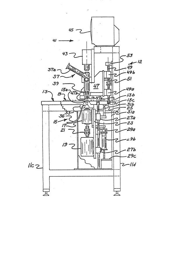
Description of-the Drawings
¦ Figure 1 i~ a perspective view of a resi~t trim
¦ tool embodying the concept~ of the applicants' invention;
Figure 2 i8 a front elevation of the re~i~t
trim tool as illu~trated in Figure l;
., ~
~'l r'FigUre 3 i9 a vertical section taken ~ubstantially
along line 3-3 of Figure 2;
Figure 4 i9 an enlarged view taken from a portion
of Figure 3 particularly illustrating the cutting, trimming
; tool, the board 3upport surface, lighting arrangement,
a manual viewing device and a bo~rd clamping device:
Figure 5 illustrate~ a cros~ section of a typical
cu~cuit boar~ wherein resi~t material i8 illu~trated covering
both ~ide~ of the board;
~igure ~ i8 a view ~imilar to Figure S wherein
. 25 the re~i~t materi~l ha~ been removed rom one ~urface
~ .
. .
.,: .
, ~ 5
2 ~ ~ 9 0 ~ 6
~f the board:
Figure 7 i~ a view ~hat would appear ~or visual,
m~nual viewing and also upon the ~lectronic ~onitor ecreen
particularly illustrating a board passage in non-centered
-position; and,
~ Figure 8 i~ a view similar to Figure 7 illustrating
; the view with a board pa-Q~age in centered position.~ De~cription of a Preferred Form of the Invéntion
~: .
In accordance with the accompanying drawings
the re~i3t trim tool is generally de~ignated 10. The
unit includes a lower framewor~ 11 having le~ lla, llb,
llc, lld and cros~ supports such a-R lle, llf. An upper
framework ic de3ignated 12 and again include~ vertical
ll uprights 12a, 12b and at least one horizontal croqs member
12c. .~he lower framework 11 provide~ a ~upporting ~tructure
j . for a ~oard 3upport ~urface 13 which, as illustrated,
i8 arranged in horizontal relationship to provide a planar
supporting ~urface for the carrying and placement of conductive
boardA which are to be resi~t trimmed.
As best illu~trated in Figure 3, the lower framework
~tructure 11 includes a vertically ~hiftable cutting and
resi~t trim tool arrangement 15 consi~ting o' a cutting
_~
, tool adaptor 17 and a drive motor 19 connected through
a clutch device 21. ~his cutting tool arrangement 15
is mounted on ramework 23 which ~ramework 23 is arranged
..
6 .
.....
C! O
.`. 21~9~6
, ~ .,
: or vertical movemen~ upon a po~itioning shaft 25 through
at lea~t a pair of bearings 27a, 27b. A drive meehanism
for ahifting the cutting tool a~sembly 15 i9 provided
and connected to the mounting plate 23 and con~iRt~ of,
in the form shown, a first elevating ~ection 29a and a
Recond elevating section 29b both of which are attached
: to a frame portion 29c associated with frame 11. The
a pect of a dual elevating mechanism 29a, 29b iB to allow
initial distance positioninq of the cutting unit 15 at
a predetermined distance from board B carried on surface
13 and allows a predetermined drive depth between a stop
31a carried by the first guide member 27a and a stop 31b
¦ on the under side of surface 13. The initial di~tance
¦ i,8 determined and ~et by the thickness of the resist material
on the board B.
A typical board from which resist material i9
to be removed i~ illustrated in Figure 5. As illustrated
, in Figure 5, the conductive portion of the board B i8
designated C and the resi~t material on the respective
sides thereo i~ designated ~1, R2. As illustrated in
Figureq 5 and 6, this resist material may be of different
thicknessse~ although it i~ standardly uniform in thickness
,_
, on each respective side. Figure 5 illu~trates a board
passage P with the resist material covering the passaye
in comparison to Figure 6 ~hich illustrates the boara
: ` :
1 0 9 0 5 6
..
: B with a trimmed ~rea T. A~ illustrated, area T iB of
~reater diameter than passage P and this view also illu~trate3
that the tool that has provided the trimmed area has not
penetrated the conductive portion C of the board B.
As particularly illu3trated in Figure 4 the
; cutter aQsembly 15 includes ~ cutting tool 15a which i~
¦;~ selected in relationship to the pa~sage P through board
a, A chuck 15b i~ provided for interchangement of ~ariou~
I sized cutting tool~ 15a~ Elevating mechanism 29b not
only allow~ for upward movement of cutter as~e~bly 15
but al~o allow~ for complete lowering of the cutter as~embly
15 f~r interchanging of cutting tools 15a.
~l As particularly illustrated in Figure 4, an
aperture 13a is provided through the support surface 13
! 15 eO allq~ the cutting tool assembly 15 to be driven upwardly
through the combined operation of the first 29a and ~econd
29b elevating mechanisms ~or resist cutting ~nd removal.
Again, as particularly illustrated in Figure 4 the stop
devices 31a, 31b control the vertical movement of the
i 20 cutter asqembly 15 such that only photo resist material
i8 cut from the board, again making reference to Figures
5 a~d 6.
As best illu.~trated in Figures 3 and 4 an illuminating
device such as a ring light 33 is provided to circumscrib~
aperture 13a and this light 33 is shielded to direct light
~ ~'~''`,:'.`'; `."''~,'~'~.,'`"`~''."''
i ~
21090~
upwardly through ~perture 13a.
a board B i~ moved ~nto position for trimming
9f the resi~t it ~hould be obviou~ that light will not
pa~ through the resist coated board ~xcept at those areas
: 5 where a pa3sage P eXi8tg in the board. ~8 the boar~ B
i8 po3itioned and properly located over the ~perture 13a
~ of 3urface 13 light will pass through the recist material
; and through the paAsage P of the board to ac~ a8 a locator
~: of the pa~Qage P. Obviously the light will be directed
concentrically with the cutting tool 15a and when the
passage P is properly centered over aperture 13a the operator
i9 insured that the cutting and trimming operation may
be initiated.
As also illustrated in Figures 3 and 4, a vacuum
may be,directed adjacent cutting tool 15a through a vacuum
line genérally designated 35. Applicants have found that
the reci~t material a~ cut by tool 15a must be removed
to maintain proper operation of the cutting tool 15a and
thus insure a properly defined trim area T in the re~ist.
Although the applicants illustrate two individual
elements 17, 19 connected through clutch 21 for cutting
and trimming operations, it should be obviou~ that this
combination only provides a driving, ~otating source or -
operation of the cutting tool 15a and this could be a
~ingle rotative source ~ithout departing from the ~copé
~""'""'~'`'`'"'
! . C) ~-'
` 21090~6
~i
of the inventionD ~pplicant~ ~ave aluo ound tha~ for
preciQeness of cut of the trim area T that the cutting
unit ~hould be relatively hig~ speed and axial alignment
iB be~t ~fforded through a combination of the drive and
~ driven elements 17, 19.
; As par~icularly illu~trated in Figure ~, variou~
stop~ such as 13b may be provided on the upper surface
.,
of support ~urface 13 for regiqtrati~n o~ identical boards
B having identically located pa~sage~ P such that each
board will not require an individual viewing to determine
proper aliynment of board passageq P ~ith the cutting
ool 15a. The ~ettable Rtop~ 13b provide for re~et placement
¦ of boards ~ once a pattern has been established.
¦ The upper a~sembly of the unit including theframework 12 combineq two individual meann for determining
proper location of the cutting areas of the board B with
respect to the cutting tool 15a. A first of theqe mean~
i5 designated 37 and includeQ manual, ~isual lenq mean~
39 which i~ vertically adju~table for specifically locating
the emitted li~ht with regard to a target passage area.
The ~econd of such viewing means is generally
de~ignated 41 and include~ an electronic camera 43 and
monitor 45. Camera 43 and the monitor 45 are electronically
connected and, as ~llustrated in Figure 3 the camera i8
: 25 aligned ~ith the ~ir~t viewi.ng system 37 such that either
.
.
;.~., '~!. .... '`' '
¦ ~ C?
i` - 21090~6
manual, vi~ual inspection may be made through an eye piec~
37a or electronic viewing as provided by the camera 43
and monitor 45.
The re3ult~ of either viewing technique are
illustrated in Figures 7 and 8. The target ~ection 39
~;~ may, a~ illu~trated, include a plurality of concentric
rings 39a with a croQs hair configuration 39b, 39c. Thi~
configuration will allow the operator to move and adjust
the po~iti~n of the board B ~uch that the passage P of
the board, which i8 light passing i~ precisely cantered
and this preciQe centering will be in alignment with the
cutting tool 15a.
¦ As also best illu~trated in Figure 3~ a clamp
~¦~ unit 47 i~ provided on the upper frameworX 12 and i~ guided
for verti:cal movement on stationary shaft 49. Shaft 49
i~ illustrated a3 being mounted in mounting block 53 and
pas~age 13c in plate 13. Clamp 47 i8 driven on ~haft
49 driven through a drive mechani~m 51. Variou~ drive
methods for shifting of clamp 47 are available and, for
~; 20 example, shaft 49 may be in the form of a ball ~crew with
drive mechani3m 51 providing rotative power to the ball
screw ~haf~ 49 with ball housing~ 49a, 49b moving the
,
:~ clamp 47 upon rotation of ~ha~t 49.
~: Clamp unit 47, in the form ~ho~n, include3 a :~
lower clamping plate 47a having an aperture 47b therethrough
,
: :
;` ~ 21099~6-- .
:
which allow~ for light passage through surface aperture
13a, the located board B and into the vi~wing ~ystem3
37, 41. After a board B is properly locat~d, preferrably
~ .
: into the position a~ illu3trated in Figure 8 the entire
clamping unit 47 i8 driven downwardly to clamp the board
; B onto the ~upport ~urface 13. Thi~ clamping arrangement
. prevents p~ssible chattering of the board B during the
'. trimming operation as aaccompli~hed through cutting tool
15a.
,1 10 It ~hould be obvious ~hat the vacuum line 35
¦ could also be utilized to hold the board B positively
¦ again~t the support 13 to prevent chattering or poissible
movement of the board 8 after the lighting alignment ha_
been accomplished.
, ~ As illustrated in Figures 5 and 6 the resiæt
material Rl, R2 i~ applied to both Aides of the conductive ~:
: member C. The resi~t material thicknesise~ may vary and
it should be obvioui~ that the setting of movement for
the cutter assembly 15 must be modified to in~ure that
only the resiist material i3 removed and there i8 no invai~ion
of the conductiv~ member C.
~ Obviou~ly, in uAe, accomodation i~ made for
changing of the cutting toolæ 15a for trimmin~ of the
resist material overlying any pai~sage and an area surrounding
3uch paissage or pa~sageQ. This i9 accompli~hed without
l ~ .
:
~,
l . 12
CJ ~!
~, .'t,`,',~,`. ' ' 21~9~5
inva~ion of the conductive board to maintain the integrity
of the board. l`he a3pect of board passage location iB
of prime i~por~ to the invention and the method of accompli~ihing
; ~uch location i~ depende~n'c only upon true location of
~ 5 the pa~sage rather than through mechanical mea~uring technique~i.
:
. :
:
.r .,
. ,`.
.
~t :
: 25