Note: Descriptions are shown in the official language in which they were submitted.
2~3~
,~0 g2/19310 PCr/US92/034i81
R~NOVABLE ~EAT-RBCOVERAB~E TI88U~ 8UPPORTING D~VICE
BACKGROUND OF THE INVENTION
Field of the Invention
This invention relates to tissue supporting
devices, preferably vascular stents for repairing blood
vessels and, more particularly, to removable devices
w~ich will temporarily and, if desired, permanently
support a dilated stenosis of a tubular organ (hollow
viscus) such as a blood vessel.
;~
Description of the Prior Art
In the past, permanent or biodegradable
devices have been developed for implantation within a
body passa~eway to maintain vascular patency. These
devices are typically characterized by the ability of
such an intravascular device to be enlarged radially
after having been introduced percutaneously, to be
transported transluminally, and to be positioned in a
desired location. These devices are either expanded
mechanically, such as by the expansion of a mandrel
positioned inside the device, or are capable of
releasing stored energy to expand themselves upon
actuation within the body.
1 ` . i ! ~
Biodegradable stent-like members using suture
materials in braided tubing or the like have been used
as vascular stents. Unfortunately, such devices are
limited in strength and application and require a
~. relatively long period of time to dissolve.
:; .
2 i ~
WO92/19310 PCT/US92/0~81
U.S. Patent Nos. 4,739,762, 4,776,337 and
4,733,665 disclose expandable and deformable
intraluminal vascular grafts in the form of thin-walled
, tubular members which are expanded radially outwardly
into contact with a body passageway, the members being
- plastically deformed beyond their elastic limit and the
members being permanently fixed within the body.
Suitable materials for the fabrication of these
tubular-shaped members would include silver, tantalum,
stainless steel, gold, titanium, or other suitable
plastic materials which may be permanently deformed.
Permànent deformation is achieved when the material is
subjected to a force which is greater than the elastic
limit of the material which is utilized to make the
tubular member. The open-mesh configuration of such
devices is soon encapsulated by body tissue and cannot
be removed. The exceeding of the elastic limit of the
material used in such devices is also believed to
compromise the performance of the devices in situ.
U.S. Patent No. 4,969,458 discloses a
vascular stent formed from a wire component made of
material, such as copper alloy, titanium, or gold,
wherein the wound configuration unwinds upon expansion
and becomes a permanent prosthesis stent, similar to
prior art devices disclosed above, and is,
unfortunately, not removable.
U.S. Patent No. 4,969,890 discloses various
configurations of shape-memory alloy members which have
been ~reviously radially compressed and which, upon
positioning within the body and thermal activation,
expand by themselves to become a permanent prosthesis
within the body. In this regard, the reference teaches
a device which operates in a similar fashion to the
device disclosed in U.S. Patent No. 4,485,816. U.S.
'092/19310 ~1 ~ ) 3 1 2 PCT/US92/0~81
Patent No. 4,485,816 discloses a shape-memory alloy
staple which, when heated, penetrates and cinches
tissue together. Shape-memory alloy historically has
been used to perform work in such a fashion wherein the
component remains in a strong austenitic state after
- temperature activation. That is, above its transition
temperature from martensite to austenite, and as the
references above disclose, the shape-memory alloy
either dilates an incompetent blood vessel or holds
segments of tissue together. Unfortunately, neither of
these devices is practically removable.
It would therefore be advantageous to have a
tissue supporting device that could be inserted into
the body while in a dimensionally compact configuration
and deformed mechanically and elastically into position
while remaining in that deformed configuration to
perform a function such as radial support, engagement
with a thrombus, etc., the device remaininq somewhat
flexible to accommodate movement of soft tissue, the
de~ice further being subsequently removable. The
subject invention provides such a device using shape-
memory alloy in ways different, essentially the
opposite, from those ~ught in the prior art.
SUMMARY OF THE INVENTION
The purpose of the invention is to provide
tissue supporting devices that are readily insertable
in a first configuration and then elastically
deforma~le into a second configuration wherein the
device exhibits a high degree of flexibility, the
device being subsequently readily removable at will.
To accomplish this purpose, there is provided a heat-
recoverable tissue supporting device of nickel-titanium
shape-memory alloy having a martensitic state, an
.
~9~
WO92/19310 . PCT/US9~/0~81
austenitic state, and a transition temperature
therebetween wherein the device is elastically
deformable from a first configuration to a second
configuration while in its martensitic state increasing
the martensite fraction of the alloy, the device being
- recoverable to the first configuration upon heating of
the device above the transition temperature to the
austenitic state for subsequent removal of the device.
By way of illustration but not limitation, a tissue
supporting device includes members which support,
filter, clamp, staple or the like which hold tissue
together or separate tissue, etc.
,
In one aspect of the invention there is
provided a tissue supporting device comprising a
recoverable member of generally tubular shape of
nickel-titanium shape-memory alloy, said alloy having
martensitic and austenitic metallurgical states and a
transition temperature therebetween, said recoverable
member being insertable within a patient while in said
martensitic state and being elastically deformable from
a first configuration while in said martensitic state
to a second configuration, increasing the martensite
fraction of the alloy, said recoverable member
providing tissue support while in said second
configuration and being recoverable to said first
configuration upon heating of said recoverable member
above said transition temperature to said austenitic
state for removal of said recoverable member from a
patient.
_
In yet another aspect of the invention there
is provided a composite tissue supporting device
comprising:
a recoverable member of nickel-titanium
shape-memory alloy, said alloy having martensitic and
~092/19310 2 1 0 ~ 3 1 ~ PCT/US92/0~81
austenitic states and a transition temperature
therebetween, said recoverable member being insertable
into a patient while in said martensitic state and
being elastically deformable while in said martensitic
state from a first configuration to a second
configuration, increasing the martensite fraction of
the alloy, said recoverable member providing tissue
support whilQ in said second configuration and being
recoverable to said first configuration upon heating
above said transition temperature to said austenitic
state; and -
a reinforcing member connected to said
recoverable member, said reinforcing member supporting
said recoverable member when both of said members are
deformed from a first configuration to a second
configuration, said reinforcing member preventing
springback of said recoverable member, the support of
said reinforcing member being overcome upon recovery of
said recoverable member to its austenitic state for
removal of both of said members from a patient.
In yet again another aspect of the invention
there is provided a tissue supporting device comprising
a recoverable member of nickel-titanium shape-memory
alloy, said recoverable member having a first
configuration and a second, deformed configuration,
said alloy having martensitic and austenitic states and
a transition temperature therebetween, said recoverable
member being deformable from said first configuration
! ' ' ! to said second configuration, increasing the martensite
fract~on of the alloy, said recoverable member
providing tissue support while in said second
. configuration and being recoverable to said first
configuration upon heating above said transition
temperature to said austenitic state.
-
21~331 )
WO92/19310 PCT/US92/0~81
DESCRIPTION OF THE DRAWING
FIG. 1 is a partial cross-sectional view of
, an embodiment of a tissue supporting device in the form
of a stent-like member positioned over a deforming
device, shown to be an angioplasty balloon, within a
partially occluded artery.
FIG. 2 is a partial cross-sectional view of
the stent-like member shown in FIG. 1 after expansion
of the angioplasty balloon which has caused elastic
deformation of the stent-like member.
FIG. 3 is a partial cross-sectional view of
the stent-like member shown in FIGS. 1 and 2 wherein
the angioplasty balloon has been contracted and removed
leaving ~he stent-like member to support the expanded
blood vessel.
FIG. 4 is a partial cross-sectional view of
the stent-like member shown in FIGS. 1-3 wherein said
stent-like member has subsequently been heated above
its transition temperature and has recovered from its
deformed configuration, as shown in FIGS. 2 and 3, to
its original configuration, as shown in FIG. 1.
FIG. SA is a perspective view illustrating an
alternate embodiment of a tissue supporting device in
the form of a stent-like member having a plurality of
longitudinal slots in a first, non-deformed
config~ration. FIG. SB is a perspective view
illustrating the stent-like member of FIG. SA after
def`ormation (shown in this case to be expansion)
creating a lattice-like structure of expanded material.
FIG. 13 discloses yet another embodiment of a stent~
~ like member in the form of a corrugated wire spring
:
:
2 ~ 3 1 ~?
`'092/19310 PCT/US92/0~81
which also provides enhanced recovery, as will be
discussed later in the specification.
FIG. 6A is a perspective view showing yet
another embodiment of a tissue supporting device in the
-5 form of a stent-like member in the form of an elongated
wire wound spring in a first configuration prior to
deformation. FIG . 6B is a perspective view showing the
stent-like member of FIG. 6A after deformation to a
second configuration, in this case through radial
expansion, the configuration of FIG. 6B ~being
recoverable to the first configuration of FIG . 6A.
FIG. 7A is a perspective view of yet another
embodiment of a tissue supporting device in the form of
a recoverable member in a first configuration. FIG. 7B
is a perspective view of the recoverable member of FIG.
7A wherein the member has been deformed longitudinally
and placed in the region of a thrombus. FIG. 7C is a
perspecti~e view similar to FIGS. 7A and 7B wherein the
member has been recovered axially to the first
configuration, shown in FIG. 7A, and in so doing has
trapped the thrombus enabling it to be removed when the
member is removed.
FIG. 8 is a perspective view of a composite
tissue supporting device in the form of a stent-like
member having a recoverable member (such as any one of
those shown in FIGS. 1-6) and a reinforcing member
:.~ i connected and concentrically mounted within the
recoverable member, both the recoverable member and the
reinforcing member being deformable from the
configuration shown in FIG. 8 to another configuration
wherein the reinforcing member supplements the strength
of the deformed recoverable member to counteract any
springback that may be experienced by the deformed
21093 1 ~
WO92/lg310 PCT/US92/0~81
recoverable memb~r when the means (not shown) for
deforming the recoverable member is removed.
FIG. 9 is a perspective view of a tissue
supporting device in the form of a stent-like member
- 5 which, for purposes of illustration, is shown to be an
elongated wire wound spring, similar to that disclosed
in FIGS. 6A and 6B, further including a retrieval
portion which can be captured by a removal tool after
the stent-like member has been inserted, deformed, and
subsequently recovered to its original configuration
for purposes of removal.
.
FIGS. lOA and lOB are perspective views
similar to FIG. 9 of alternate embodiments of a tissue
supporting device in the form of a stent-like member
illustrated as elongated wire wound springs wherein the
general shape of the stent-like member in its original
configuration facilitates the capture and removal of
the stent-like member. FIG. lOA ill11strates a "wish-
bone" configuration capable of recovering onto a
removal tool (not shown) having a detent complementary
with the center portion of the stent-like member. FIG.
lOB illustrates a stent-like member having an enlarged
center section which can recover onto the bulbous
portion of a removal tool (not shown).
FIGS. llA and llB illustrate in perspective
view yet another embodiment of a tissue supporting
device in the form of a stent-like member wherein the
first~configuration of the stent-like member is shown
~;~ in FIG. llA, and the deformed configuration is shown in
FIG. llB. This embodiment can generally surround and
compress the body portion and can be subsequently
removed upon expansion from its original configuration,
~ ' .
:::
~092/19310 2 1 ~ ~ 3 1 C~ PCT/US92/0~81
FIG. 12 illustrates in exploded perspective
view another embodiment of a tissue supporting device
in the form of a stent-like member. In FIG. 12A the
stent-like member is in its first configuration. In
FIG. 12B the member is deformed, for example, into a
coil shape outside of the body. In FIG. 12C the
deformed stent-like member is inserted within a duct in
the body, for example, a tube that has been previously
severed and is sewn together around the deformed stent-
like member, a portion of the stent-like member
extending through the wall of the tube for subsequent
retrieval. In FIG. 12D a removal tool has captured the
end of the deformed stent-like member and progressively
heats portions of the stent-like member, such as by the
application of a hot fluid, the stent-like member
recovering to its first configuration, as shown in FIG.
12A. FIG. 12E shows the duct and the recovered and
removed stent-like member.
FIG. 13 is a perspective view showing another
embodiment of a tissue supporting device in the form of
a stent-like member in the form of a corrugated wire
spring.
DESCRIPTION OF THE PREFERRED EMBODIMENTS
With continued reference to the drawing, FIG.
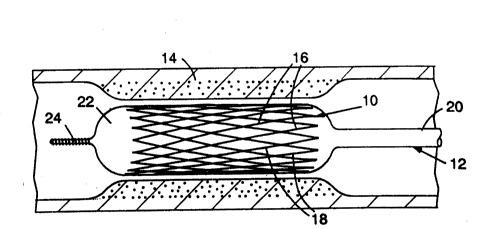
l illustrates a tissue supporting device in the form of
a stent-1ike member shown as recoverable member l0
carried by angioplasty device 12 and positioned within
a part~lly or totally occluded artery 14 or other
hollow viscus. Recoverable member l0 is radially
deformable having a plurality of wire portions 16 and
18 that are at an angle to each other and to the
longitudinal axes of tube-like recoverable member l0.
It is understood that wire portions 16 and 18 are
:
WO92/19310 PCT/US92/0~81
--10--
connected together, as appropriate, to provide the
degree of support necessary for recoverable member lO.
Recoverable member lO is made of shape-memory
alloy, preferably nickel-titanium shape-memory alloy,
the alloy having a martensitic metallurgical state, an
austenitic metallurgical state, and a transition
temperature therebetween. Wire portions 16 and 18 may
have various cross-sectional shapes, as required.
Shape-memory alloys, i.e., memory metals, are
alloys which manifest the shape-memory effect. Such
alloys are well known, and they and the shape-memory
effect are discussed, for example, in "Shape-Memory
Alloys", Scientific American, Vol. 281, pages 74-82
(November, 1979). The shape-memory effect can actually
15 constitute two separate phenomena, one generally -
referred to as heat-recoverability, and the other
phenomenon generally referred to as pseudoelasticity.
In reality, the two phenomena are intertwined, and the
subject invention takes advantage of each.
Shape-memory alloys are disclosed in U.S.
Patent Nos. 3,012,882 and 3,174,851. As made clear in
these patents, these alloys undergo a transition
between an austenitic state and a martensitic state at
certain temperatures. When they are deformed while in
the martensitic state they will retain this deformation
as long as they are maintained in this state but will
revert to their original configuration when they are
heate~ to a transition temperature, at which time they
~; transform to their austenitic state. The temperatures
at which these transitions occur are effected by the
nature of the alloy and the conditioning of the
material. Nickel-titanium based alloys wherein the
transition temperature is slightly higher than body
92/19310 ~1 ~ 3 31~ PCT/US92/0~81
temperature are preferred for the subject invention.
It is desirable to have the transition temperature hi~h
enough so that the transition temperature will not be
, reached upon exposure of the body to ambient
temperature increases, but low enough such that the
alloy can be heated without causing significant damage
to the tissues of the body.
The heat-recoverability of recoverable member
lO is illustrated in FIGS. 1-4 wherein recoverable
member lO is deformed while in its martensitic
metallurgical state and is subsequently recovered ~y
heating recoverable member lO through its transition
temperature into its austenitic metallurgical state.
In FIG. l, recoverable member lO is inserted by means
lS of angioplasty device 12 having lumen portion 20,
balloon portion 22 and guide portion 24. Recoverable
member lO is positioned about balloon portion 22.
In FIG. 2, balloon portion 22 has been
expanded, thus deforming recoverable member lO radially
outwardly against occluded artery 14. The cross-
section of wire portions 16 and 18 may be optimized to
assist in the angioplasty procedure - such as by the
use of a wire with a sharp outer edge to pre-incise the
tissue thus causing a more uniform dilatation.
Although the subject invention is initially being
described as a part of an angioplasty procedure, it is
understood that the invention is not limited to such a
procedure or to the use of a stent-like member in an
artery-. It should be apparent to one skilled in the
art that the subject invention is useful in supporting
body issue in general as well as various arteries
besides a coronàry artery, e.g., in saphenous vein
grafts, the vena cavae, the aorta, the renal artery,
the iliac artery, the femoral artery, the popliteal
2 1 ~
WO92/19310 PCT/US92~0~81
-12-
artery, the carotid artery, the cranial arteries,
pulmonary arteries, etc. The various embodiments of
the invention are also useful with other tubular organs
, including but not limited to the prostate, the biliary
tract, the esophagus, the trachea, the fallopian tubes,
- the vas deferens, the ureters, the tear ducts, the
salivary ducts, etc.
In FIG. 3, angioplasty device 12 (not shown)
has been removed by collapsing the balloon portion, and
recoverable member lO is left in place to support
artery 14. After a suitable period of time, as
determined by the physician, recoverable member lO may -
be removed (unlike the prior art devices discussed
earlier~. As seen in FIG. 3, the alloy of recoverable
member lO remains in the martensitic metallurgical
state to support healing artery 14. Recoverable member
lO has been elastically deformed increasing the
martensite fraction of the alloy. The devices ;
disclosed in U.S. Patent Nos. 4,739,762, 4,776,337 and
20 4,733,665 exceed the elastic limit of the material of
the thin-walled tubular members in the deformation
process and consequently destroy material properties.
Recoverable member lO of the subject invention is not
permanently deformed and therefore provides improved
support to the supple tissue that is being assisted
during the healing process.
In FIG. 4, removal means 26 is introduced to
! ~ i recover and capture recoverable member lO. For purpose
of illustration, removal means 26 is shown to have tube
30 portion 28 and gripping portion 30. Removal means 26
is introduced by a catheter or the like such that
gripping portion 30 engages a portion of recoverable
member lO. Subsequently, a warm fluid 31 is pumped
through tube portion 28 to heat recoverable member lO
Y092/19310 2 ~ ~ 9 3 1 ~ PCT/US92/0~81
-13-
above the transition temperature of the alloy to
elevate the alloy to its austenitic metallurgical
state, thus recovering recoverable member lO from its
second configuration, as shown in FIG. 3, to its first
configuration, shown in FIG. l. Recoverable member lO
is shown in FIG. 4 to have recovered from the deformed
second configuration t~ its first configuration, as
shown in FIG. l. Recoverable member lO may then be
removed.
Another method of obtaining a deformed
martensitic state in recoverable member lO is to cool
an appropriately "trained" recoverable member lO below
its martensitic transformation temperature within the
body without using an angioplasty device having a
balloon portion, as described earlier. Some heat-
recoverable alloys after repeated cycling become
"trained". This procedure is known to those skilled in
the art and can be performe~ on recoverable member lO
outside of~the body. An external mechanical means for
expansion is no longer required, and the "trained"
recoverable member will spontaneously expand. The
trained recoverable member is introduced into the body
on a warm catheter device which maintains the member in
its recovered austenitic metallurgical state. The
member is then allowed to cool and expand. The member
can subsequently be retrieved, as described earlier.
Such a phenomenon is discussed in Treatises in
M_ allurqv edited by J.F. Tien and J.F. Elliott, 1981,
in the chapter entitled "Fundamentals of Martensite
Reaction" by M. Cohen and C.M. Wayman. This chapter is
incorporated herein by reference. This behavior of the
material is often referred to as its "two-way" shape-
memory effect.
21~3~
WO92/19310 PCT/US92103481
An alternate embodiment of the subject
invention is also illustrated by recoverable member lO,
as seen in FIG. 4, wherein recoverable member lO
fabricated from a trained alloy in a first
configuration is introduced into the body by a tool
similar to removal means 26 and is subjected to warm
fluid 31. When recoverable member lO cools it expands
to do work similar to the work performed by the devices
disclosed in U.S. Patent Nos. 4,739,762, 4,776,337 and
4,733,665. However, this is accomplis~ed without the
use of an expansion-member and, again, with the
capability of subsequently being removed completely
(unlike the prior art devices) by heating recoverable
member lO through the introduction of a warm fluid to
- 15 heat the device above the transition temperature of the
alloy, as described earlier with regard to FIGS. 1-4.
FIG. 5A illustrates an alternate embodiment
of a tissue supporting device in the form of a stent-
like member in the form of recoverable member 32 having
~0 a plurality of longitudinal slots 34 (which are
perforations.that are of a particular range) that is :
generally rectangular and is arranged in a particular
pattern that is in the form of a rhombic lattice. FIG.
5B illustrates the expansion of recoverable member 32,
, 25 which may be referred to as a slotted tube, from its
first configuration, shown in FIG. 5A, to its second
configuration, shown in FIG. 5B. A rhombic lattice is
created by the interconnection of the geometric centers
! i~ of perforations 36, as clearly seen in FIG. 5B. The
rhombi~c lattice clearly allows expansion or contraction
of the grid-like structure. ~ecoverable member 32,
shown in its first configuration in FIG. 5A, is
deformed to the second configuration, shown in FIG. 5B,
and may be subsequently recovered to the first
configuration upon heating recoverable member 32 above
2 i ~31~
'092/19310 PCT/US92/03481
the transition temperature of the shape-memory alloy
from which it is fabricated. The lattice-like
- structure disclosed in FIGS. 5A and 5B provides
, enhanced recovery beyond the 4-9~ heat recovery
inherent in the shape-memory alloy. U.S. Patent No.
4,390,599, which is incorporated herein by reference,
discloses the enhanced recovery of such a structure.
The subject invention is an improvement over that
disclosed in the aforementioned patent in that the
subject invention applies such a structure to the
unique medical application for the clearly advantageous
purpose of removing a deformed supporting element using
heat recovery of shape-memory alloy. -
FIG. 6A discloses yet another embodiment of a
tissue supporting device in the form of a stent-like
member in the form of heat-recoverable member 38 which
is an elongated wire wound spring-like member including
what can be described as a serpentine coil (not shown)
which, analogous to the description of the subject
invention above, is in a first configuration in FIG. 6A
and is in a deformed, second configuration in FIG. 6B.
FIG. 7A is a perspective view of yet another
embodiment of a tissue supporting device in the form of
a stent-like member in the form of recoverable member
40 which is an elongated helically wound wire-like
member of shape-memory alloy which is deformable, as
shown in FIG. 7B, longitudinally and which when placed
proximate to thrombus 41 and recovered from the second
config~ration, shown in FIG. 7B, to the first
configuration, shown in FIG. 7A, captures thrombus
material 4l, as seen in FIG. 7C.
FIG. 8 illustrates yet another embodiment of
a tissue supporting device in the form of a stent-like
wo s2~lg3l~ 1 0 ~
PCT/US92/03481
-16-
member comprising recoverable member 4~ of shape-memory
alloy and reinforcing member 44 concentrically mounted
within recoverable member 42. Both recoverable member
~ 42 and reinforcing member 44 are deformable from a
first configuration to a deformed, second configuration
and are recoverable, as discussed above, to the first
configuration for removal of the stent-like member.
Recoverable member 42 may be similar in structure to
any of the recoverable members shown in FIGS. 1-6 and-
may be deformed by means of expansion within the bodyby mechanical means to a second configuration and
subsequently-recovered to its first con~iguration by
elevating the temperature of the device above the
transition temperature of the shape-memory alloy. Upon
deformation, specifically expansion, of recoverable
member 42, some springback to a smaller configuration
may be experienced by recoverable member 42 when
mechanical deforming means, such as a balloon portion
of an angioplasty device (not shown), is removed.
Reinforcing member 44 is made from a more ductile
material and may be crimped while in the unexpanded
state by recoverable member 42 when it is transformed
to the austenitic state. It is within the scope of the
invention to connect reinforcing member 44 to
recoverable member 42 by various means such as
laminating, cladding, etc. Suitable materials for
reinforcing member 44 are stainless steel, gold,
tantalum, etc.
It is understood that it is within the scope
of the invention to use various mechanical means to
deform the shape-memory alloy recoverable members.
FIGS. l and 2 illustrate the balloon portion of an
angioplasty device being used to expand the deformable
member. Other mechanical means such as expandable
braided members, a plurality of thin metallic members
!o g2/193lo 2 ~ 3 1 ~ PCT/US92~0~81
actuated mechanically to expand in diameter, etc. are
considered to be within the scope of the invention.
FIG. g illustrates recoverable member 46
having retrieval portion 48 shown to be a hook- or
eyelet-shaped portion of recoverable member 46. It is
within the scope of the invention to provide other
apertures or extensions such as a tether wire or the
like which may comprise a retrieval portion.
~ FIGS. lOA and lOB illustrate recoverable
members 50 and 52-, the overall first configurations of
which provide means for retrieval of the members
subsequent to heat recovery to their first
configurations. Recoverable member 50 is shown to be a
wire wound member having a wish-bone configuration
which can cinch down on a removal tool having a detent
or the like. FIG. l0B illustrates recoverable member
52 having an enlarged center portion which can likewise
recover on top of a bulbous portion of a removal tool
(not shown) when recovered.
Heat recovery of the various embodiments of
recoverable members can be accomplished by a variety of
means known to one skilled in the art. FIG. 4
illustrates means to introduce a warm fluid which
elevates the temperature above the transition
25 temperature of the alloy. Other means of locally `
applying heat, such as magnetic inductance, electrical
resistance, etc., are considered to be within the scope
of the~~invention.
.
FIGS. llA and llB illustrate the concept of
recoverable member 54 having a first configuration, as
shown in FIG. llA, which is deformed to a second
configuration 56, as shown in FIG. llB, which is
Wo92/l93lo ~ 1 0 9 31~ PCT/US92~0~81
-18-
radially smaller to support a component externally
rather than internally.
FIG. 12 illustrates yet another embodiment of
a tissue supporting device in the form of a stent-like
member wherein recoverable member 58 is shown in FIG.
12A to be generally straight in a first configuration
and is shown in FIG. 12B to have been deformed outside
of the body into a coiled second configuration 60
having a retrieval portion 62~ In FIG. 12C-coiled
second configuration 60 is introduced into the body,
such as at the joining of previously severed tubes of
the body, e.g., reconnection of the vas deferens
previously severed in a vasectomy, and retrieval
portion 62 is permitted to extend through the wall of
15 the tube, or vas deferens, 64 during the healing `
period. -In FIG. 12D, recoverable member 58 is shown
being removed with the assistance of removal tool 66
shown to be a tube into which retrieval portion 62 has
been drawn while warm fluid 67 is pumped through the
20 tube. The result is the progressive recovery of
recoverable member 58 from its coiled second
configuration 60, shown in FIG. 12B, to its first
configuration, as shown in FIG. 12A, while it is being
drawn into removal tool 66 through the small opening
25 remaining in the tubular portion of the body~ FIG. 12E
shows the healed tubular portion of the body with
recoverable member 58 fully contained within removal
tool 66.
^ FIG. 13 illustrates yet another stent-like
30 member in the form of recoverable member 68 which is a
corrugated wire which has been wound into a coil, the
corrugations of the wire allowing enhanced recovery
c when the wire has been deformed by straightening beyond
092/19310 21~ t~ 3 ~ ~t PCT/US92/0~81
--19--
the point of the overall recovery of the coils which
have themselves been deformed by means of expansion.
All of the above-described tissue supporting
devices may also be used to deliver drugs or other
-5 physical or chemical agents, e.g., electric charge
radioactive materials, etc. by either coating any of
the recoverable members with drug releasing materials
or by providing a separate layer of drug releasing
materials. The materials are released by means of
contact, dissolution, pressure, etc. See optional
coating or layer 70 shown in phantom in FIGS. 5A and
5B. All of the above tissue supporting devices may be
coated with biologically inert coatings to improve
their biological compatibility, if desired.
l5While the invention has been particularly
shown and described with reference to the preferred ;
embodiments thereof, it will be understood to those
skilled inrthe art that the foregoing and other changes
in form and details may be made therein without
departing from the spirit and scope of the invention,
limited only by a just interpretation of the following
claims.
.