Note: Descriptions are shown in the official language in which they were submitted.
- 1 -
TITLE OF THE INVENTION
A MULTILAYER INSULATED WIRE AND
A MANUFACTURING METHOD THEREFOR
BACKGROUND OF THE INVENTION
Field of the Invention
The present invention relates to a multilayer
insulated wire having three or more insulating layers
and a manufacturing method therefor, and more
particularly, to a multilayer insulated wire, which
enjoys a high coilability and is adapted for use as a
winding or lead wire of a transformer incorporated in
electrical or electronic equipment, and in which
separability between insulating layers is so good that
the insulating layers can be removed, and solder is
allowed to adhere to a conductor in a short period of
time when they are dipped in a solder bath, so that
the solderability is high, further the insulation
properties of the insulating layers cannot be easily
lowered with time, and a manufacturing method for the
multilayer insulated wire.
Prior Art
The construction of a transformer is prescribed
by IEC (International Electrotechnical Communication)
standards Pub. 950, 65, 335, 601, etc. These
standards provide that an enamel film which covers a
conductor of a winding be not authorized as an
insulating layer, and that at least three insulating
layers be formed between primary and secondary
windings or the thickness of an insulating layer be
0.4 mm or more. The standards also provide that the
creeping distance between the primary and secondary
- 2 -
windings, which varies depending on the applied
voltage, be 5 mm or more, that the transformer
withstand a voltage of 3,000 V applied between the
primary and secondary sides for a minute or more, and
the like.
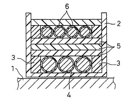
Accordingly, a currently prevailing transformer
has a profile such as the one illustrated in Fig. 1.
Referring to Fig. 1, a flanged bobbin 2 is fitted on a
ferrite core 1, and an enameled primary winding 4 is
wound around the bobbin 2 in a manner such that
insulating barriers 3 for securing the creeping
distance are arranged individually on the opposite
sides of the peripheral surface of the bobbin. An
insulating tape 5 is wound for at least three turns on
the primary winding 4, additional insulating barriers
3 for securing the creeping distance are arranged on
the insulating tape, and an enameled secondary winding
6 is then wound around the insulating tape.
Recently, a transformer which includes neither
the insulating barriers 3 nor the insulating tape 5,
as shown in Fig. 2, has started to be used in place of
the transformer having the profile shown in Fig. 1.
The transformer shown in Fig. 2 has an advantage
over the one shown in Fig. 1 in being able to be
reduced in overall size and dispense with the winding
operation for the insulating tape.
In manufacturing the transformer shown in Fig. 2,
it is necessary, in consideration of the aforesaid IEC
standards, that at least three insulating layers 4b
(6b), 4c (6c), and 4d (6d) are formed on one or both
of conductors 4a and 6a of primary and secondary
windings 4 and 6 used, and that the individual
t.~ k
- 3 -
insulating layers can be separated from one another.
One such known winding is described in Jpn. UM
Appln. KOKAI Publication No. 3-106626. In this case,
an insulating tape is first wound around a conductor
to form a first insulating layer thereon, and is
further wound to form second and third insulating
layers in succession. Thus, three insulating layers
are formed so as to be separable from one another. In
another known winding disclosed in Jpn. UM Appln.
KOKAI Publication No. 3-56112, a conductor enameled
with polyurethane is successively extrusion-coated
with fluoroplastics, whereby extrusion-coating layers
composed of three layers structure are formed for use
as insulating layers.
In the former case, however, winding the
insulating tape is an unavoidable operation, so that
the efficiency of production is extremely low, thus
entailing increased manufacturing cost.
In the latter case, the insulating layers, which
are formed of fluoroplastics, enjoy a satisfactory
thermal resistance. Since the adhesion between the
conductor and the insulating layers and between the
insulating layers is poor, however, the resulting
insulated wire lacks in reliability.
In coiling the insulated wire, it is guided
through a guide nozzle as it is wound around a coil
bobbin. During this operation, the insulating layers
may be easily separated from the conductor as the
insulated wire rubs against the guide nozzle, or the
insulating layers may be separated from one another.
If the wire in this state is wound around the coil
bobbin, the insulating layers are torn by the
- 4 -
friction between the adjacent turns of the insulated
wire or the like. In this situation, the electrical
properties, e.g., dielectric breakdown properties, of
the resulting coil are spoiled.
The insulating layers cannot be removed by being
dipped into a solder bath. In processing terminals
for the connection between the insulated wire and lead
pins, for example, therefore, the insulating layers at
the terminals must be removed by some low-reliability
mechanical means.
In order to solve such problems as aforesaid, an
investigation is being made into an arrangement such
that a conductor is extrusion-coated with a
polyethylene terephthalate (PET) resin, which enjoys
high electrical insulation properties and thermal
resistance and easily decomposes at the melting
temperature of solder, to form an insulating layer.
However, this PET resin cannot fulfill its proper
thermal resistance and mechanical properties until it
is crystallized under appropriate conditions which
make that resin orientate. Therefore, a highly
crystallized insulating layer cannot be obtained by
extrusion-coating, so that the dielectric strength
requires improvement.
In the case of a wire in which all three
insulating layers are formed of the PET resin, there
is room for improvement in the insulation properties
of a coil formed by coiling the wire.
This problem may be attributable to the following
circumstances. Since the surface of each PET resin
layer, formed as an insulating layer, has a high
coefficient of friction, the insulating layers are
?2465-56
liable to cracking or damages as they rub against the guide nozzle
of a coiling machine during coiling operation. Moreover, the
adhesion between the insulating layers, formed the PET resin, is
so good that cracks and the like in the outermost layer easily
affect the lower insulating layers due to a notch effect.
Also known is an insulated wire, though not multilayer,
in which a bondable layer is formed as the outermost layer by
coating a resin such as polyamide on the surface of an enameled
wire by baking.
The insulated wire is wound into a coil. As a high-
intensity current is passed through the coiled wire, the coiled
wire generates heat, whereby the polyamide forming the bondable
layer melts and adjacent turns of the coiled wire become bonded to
each other (usually called electric heating method).
Alternatively, When the insulated wire is coiled, the polyamide
forming the bondable layer may be melted by blowing hot air toward
the coiled portion of the insulated wire, thereby bonding the
coiled wire (usually called hot air blowing method). Further, the
turns of the insulated wire can be bonded together by using a
solvent.
Thus, since the adjacent turns of the bondable-type
insulated wire are bonded to each other, the coil is prevented
from being loosened. Accordingly, the reliability of the coil
produced is enhanced, and also the productivity is increased.
Usually, the bondable layer of the above-described
insulated wire is formed by applying a paint, which is composed of
a bondable resin dissolved in a solvent, to the surface of an
enameled wire and then baking the resulting structure.
5a 72465-56
Accordingly, the wettabilitY of the interface between the bondable
layer and an insulating film covering the enameled wire is
improved, so that the bondable layer can firmly adhere to the
insulating film with ease. Thus, various materials can be
utilized for the bondable layer.
If a multilayer insulated wire, like the insulated wire
described above, is formed having the bondable layer outside the
triple insulating layers, the resulting coil can be prevented from
loosening by
~ 1~~~~
- 6 -
the high-bonding strength of the bondable layer during
the coiling operation, and the reliability of the
coiling operation can be improved.
However, no solvent is used for the manufacturing
of the bondable multilayer insulated wire in which the
individual insulating layers and the bondable layer on
the outermost insulating layer are formed by
extrusion-coating. Unlike the enameled wire,
therefore, this insulated wire cannot enjoy the effect
of the solvent to improve the wettability of the
interface between the bondable layer and the outermost
insulating layer positioned under the bondable layer.
Accordingly, the force of adhesion between the
bondable layer and the outermost insulating layer
cannot be very great.
When the bondable multilayer insulated wire is
coiled, therefore, the outside bondable layer
sometimes may be separated from the insulating layer
thereunder or scraped off by friction with the guide
nozzle. Thus, even if the bondable layer remains on
the outermost insulating layer, its adhesiveness is
lowered considerably.
In the case of a multilayer insulated wire which
complies with the aforementioned IEC standards,
interlaminar separation between at least three
insulating layers is in the state of being possible.
If the bondable layer, the outermost layer, is
separated or scraped off and adheres to the inner
surface of the guide nozzle, therefore, the following
awkward situations are liable to be entailed.
First, a tension which acts on the insulated wire
being wound increases, so that snapping of the wire is
PJ
caused between the guide nozzle and the coil bobbin.
Further, the constituent resin of the bondable layer
adhering to the inner surface of the guide nozzle rubs
against the insulating layers, thereby tearing the
insulating layers, and moreover, causing the
insulating layers to be separated from one another.
If the insulated wire is wound around the coil bobbin
in this state, the insulating layers are torn by the
friction between the adjacent turns of the wound wire.
If the insulating layers are torn in this manner,
the electrical insulation properties, e.g., dielectric
breakdown properties, of the coil are ruined.
SUMMARY OF THE INVENTION
An object of the present invention is to provide
a multilayer insulated wire, which complies with the
IEC standards, enjoying good solderability and high
coilability, and in which the electrical insulation
properties of insulating layers lower less with time,
and a manufacturing method for the wire.
Another object of the present invention is to
provide a bondable multilayer insulated wire, which
complies with the IEC standards, enjoying good
solderability, and can be coiled with high reliability
without entailing separation of a bondable layer from
the insulating layer, and a manufacturing method for
the wire.
In order to achieve the above objects, according
to the present invention, there is provided a
multilayer insulated wire comprising a conductor and
three or more insulating layers covering the
conductor, in which each of first and second
8 72465-56
insulating layers, as counted from the conductor side, is (a) an
extrusion-costing layer (hereinafter referred to as extrusion-
coating layer a) of an intimate resin mixture compounded so that
an ethylene-based copolymer, having a carboxylic acid or a metal
salt of the carboxylic acid on the side chain thereof, accounts
for 5 to 40 parts by weight compared to 100 parts by weight of a
thermoplastic straight-chain polyester resin formed by combining
an aliphatic alcoholic constituent and an acid constituent, (b) an
extrusion-coating layer (hereinafter referred to as extrusion-
coating layer b) consisting mainly of a thermoplastic straight-
chain polyester resin, the whole or a part of which is formed by
combining a cycloaliphatic alcoholic constituent, preferably
cyclohexanedimethanol, and an acid constituent, or (c) an
extrusion-coating layer (hereinafter referred to as extrusion-
coating layer c) of an intimate resin mixture compounded so that
the ethylene-based copolymer, having a carboxylic acid or a metal
salt of the carboxylic acid on the side chain thereof, accounts
for 50 parts or less by weight compared to 100 parts by weight of
a thermoplastic straight-chain polyester resin, the whole or a
part of which is formed by combining a cycloaliphatic alcoholic
constituent preferably cyclohexanedimethanol, and an acid
constituent, and a third insulating layer is an extrusion-coating
layer of a thermoplastic polyamide resin or a intimate resin
mixture consisting mainly of the thermoplastic polyamide resin.
According to the present invention, moreover, there is
provided a manufacturing method for a multilayer insulated wire,
comprising cooling the surface of a first and/or second extrusion-
coating layer to 100°C or below when extrusion-coating of three or
9 ~ ~ ~ 3 ~ ~ 72465-56
more insulating layers is finished, in forming the insulating
layers on the surface of a conductor by extrusion-coating.
According to the present invention, furthermore, there
is provided a bondable multilayer insulted wire comprising a
conductor, three or more insulating layers covering the surface of
the conductor, and a bondable layer covering the outermost one of
the insulating layers, in which each of first and second
insulating layers, as counted from the conductor side, is (a) an
extrusion-coating layer (hereinafter referred to as extrusion-
coating layer a) of a intimate resin mixture compounded so that an
ethylene-based copolymer, having a carboxylic acid or a metal salt
of the carboxylic acid on the side chain thereof, accounts for 5
to 40 parts by weight compared to 100 parts by weight of a
thermoplastic straight-chain polyester resin formed by combining
an aliphatic alcoholic constituent and an acid constituent, (b) an
extrusion-coating layer (hereinafter referred to as extrusion-
coating layer b) consisting mainly of a thermoplastic straight-
chain polyester resin, the whole or a part of which is formed by
combining a cyloaliphatic alcoholic constituent, preferably
cyclohexanedimethanol, and an acid constituent and an alcoholic
constituent the whole or a part of which is cyclohexanedimethanol,
or (c) an extrusion-coating layer (hereinafter referred to as
extrusion-coating layer c) of an intimate resin mixture compounded
so that the ethylene-based copolymer, having a carboxylic acid or
a metal salt of the carboxylic acid on the side chain thereof,
accounts for 50 parts or less by weight compared to 100 parts by
weight of the thermoplastic straight-chain polyester resin, the
whole or a part of which is formed by combining a cycloaliphatic
72465-56
alcoholic constituent, preferably cyclohexanedimethanol, and an
acid, a third insulating layer is an extrusion-coating layer of a
thermoplastic polyamide resin or a intimate resin mixture
consisting mainly of the thermoplastic polyamide resin, and the
bondable layer is an extrusion-coating layer of an interpolyamide
resin.
BRIEF DBSCRIPTION OF THE DRAWINGS
Fig. 1 is a sectional view showing an example of a
10 transforrner having a conventional construction; and
Fig. 2 is a sectional view showing an example of a
transformer in which three-layer insulated wires are used as
windings.
DETAILED DESCRIPTION OF THE INVENTION
In a multilayer insulted wire or bondable multilayer
insulted wire according to the present invention, first and second
insulating layers, as counted from the conductor side, may be
formed of layers of only one type selected from extrusion-coating
layers a, b and c or of different types individually.
In this case, the wire whose first and second insulating
layers are formed of the extrusion-coating layer a each is an
insulated wire which enjoys a particularly high solderability.
On the other hand, the wire whose first and second
insulating layers are formed of the extrusion-coating layer b or c
each is an insulated wire which enjoys a particularly high thermal
resistance.
In each of the wires described above, resins or
y
- 11 -
intimate resin mixtures used to form the first and
second insulating layers may be different in
compositions.
In the case of forming the first and second
insulating layers such that one layer is formed by the
layer ~ and another layer is formed by layer li or
then the resulting multilayer insulated wire is well-
balanced in solderability and thermal resistance.
The intimate resin mixture which constitutes the
extrusion-coating layer r~ contains a thermoplastic
straight-chain polyester resin and an ethylene-based
copolymer as essential ingredients.
Available examples of the thermoplastic straight-
chain polyester resin are materials which are obtained
by an esterification reaction between aliphatic diol
and an aromatic dicarboxylic acid or a dicarboxylic
acid obtained by replacing part of the aromatic
dicarboxylic acid with an aliphatic dicarboxylic acid.
Typical examples include polyethylene terephthalate
(PET) resin, polybutylene terephthalate (PBT) resin,
polyethylene naphthalate resin, etc.
Available aromatic dicarboxylic acids for the
synthesis of the thermoplastic straight-chain
polyester resin include, for example, terephthalic
acid, isophthalic acid, terephthal dicarboxylic acid,
diphenylsulfone dicarboxylic acid, diphenoxyethane
dicarboxylic acid, diphenylether dicarboxylic acid,
methyl terephthalic acid, methyl isophthalic acid,
etc. Among these acids, terephthalic acid is
particularly appropriate.
Available aliphatic dicarboxylic acids for the
partial replacement of the aromatic dicarboxylic acid
v
- 12 -
include, for example, succinic acid, adipic acid,
sebacic acid, etc. Preferably, the displacement of
these aliphatic dicarboxylic acids is less than 30
mol% of the aromatic dicarboxylic acid, and more
preferably less than 20 mol$.
Available aliphatic diols for the esterification
reaction include, for example, ethylene glycol,
trimethylene glycol, tetramethylene glycol, hexane
diol, decane diol, etc. Among these materials,
ethylene glycol and tetramethylene glycol are
appropriate. The aliphatic diols may partially
contain oxy glycols, such as polyethylene glycol,
polytetramethylene glycol.
Other essential ingredients of the intimate resin
mixture which constitutes the extrusion-coating layer
~ may, for example, be an ethylene-based copolymer
having a carboxylic acid or its metal salt on the side
chains of polyethylene.
This ethylene-based copolymer serves to restrain
the thermoplastic straight-chain polyester resin from
crystallizing, thereby inhibiting deterioration of the
electrical properties of the formed insulating layers
with time, and contributing to the security of good
separability between the first and second insulating
layers.
Available carboxylic acids to be bonded include,
for example, unsaturated monocarboxylic acids, such as
acrylic acid, methacrylic acid, crotonic acid, etc.,
unsaturated dicarboxylic acids, such as malefic acid,
fumaric acid, phthalic acid, etc. Further, available
metal salts include zinc, sodium, potassium,
magnesium, etc.
- 13 -
Available ethylene-based copolymers include, for
example, resins (e. g., HI-MILAN (trademark) produced
by Mitsui Polychemical Co., Ltd.) containing
carboxylic metal salts as a part of an ethylene-
methacrylate copolymer and generally referred to as
ionomers, ethylene-acrylate copolymers (e.g., EAA
(trademark) produced by Dow Chemical, Ltd.), and
ethylene-based graft polymers (e. g., ADMER (trademark)
produced by Mitsui Petrochemical Industries, Ltd.)
having a carboxylic acid on their side chains.
This intimate resin mixture is compounded so that
the ethylene-based copolymer accounts for 5 to 40
parts by weight compared to 100 parts by weight of the
thermoplastic straight-chain polyester resin.
If the loading of the ethylene-based copolymer is
less than 5 parts by weight, the thermal resistance of
the formed insulating layers is satisfactory, but its
effect of restraining the crystallization of the
thermoplastic straight-chain polyester resin is
reduced. Accordingly, the so-called crazing is caused
by coiling such that the surface of the insulating
layers suffers micro-cracking. Also, degradation of
the insulating layers advances with time, thereby
considerably lowering the dielectric breakdown
voltage. If the loading of this copolymer exceeds 40
parts by weight, on the other hand, the thermal
resistance of the insulating layers is inevitably
lowered to a substantial degree. Preferably, the
ethylene-based copolymer should account for 7 to 25
parts by weight compared to 100 parts by weight of the
thermoplastic straight-chain polyester resin.
The material of the extrusion-coating layer li is
- 14 -
a thermoplastic straight-chain polyester resin having
the following composition.
This material is a straight-chain polyester resin
which is formed by combining an acid constituent and
an alcoholic constituent the whole or a part of which
is cyclohexanedimethanol, an alicyclic alcohol.
~~ Specifically, polycyclohexanedimetY~ylene terephthalate
(PCT) resin may be used for this purpose. This resin
has a higher thermal resistance than the aforesaid PET
resin and the like.
In consideration of the requirement that the.
dielectric breakdown voltage should be restrained from
being lowered by the degradation of the insulating
layers, moreover, a modified resin should preferably
be formed by blending 10 to 100 parts by weight of,
e.g., a polyamide resin, polycarbonate resin, or
polyurethane resin with 100 parts by weight of the
thermoplastic straight-chain polyester resin.
Preferred PCT resins include, for example, EKTAR-
DN, EKTAR-DA, and EKTAR-GN (trademarks; produced by
Toray Industries, Inc.).
The intimate resin mixture which constitutes the
extrusion-coating layer ~. is an intimate mixture of
the aforesaid PCT resin and the ethylene-based
copolymer as an essential ingredient of the intimate
resin mixture used for the formation of the extrusion-
coating layer sZ.
This intimate resin mixture is compounded so that
the ethylene-based copolymer accounts for 50 parts or
less by weight compared to 100 parts by weight of the
PCT resin.
If the loading of this copolymer exceeds 50 parts
- 15 -
by weight, the PCT resin cannot exhibit its high
thermal resistance, so that the resulting insulating
layers cannot enjoy a good thermal resistance.
Preferably, the ethylene-based copolymer should
account for 5 to 30 parts by weight compared to 100
parts by weight of the PCT resin.
A third insulating layer of the multilayer
insulated wire according to the present invention is
formed of a thermoplastic polyamide resin or an
intimate resin mixture consisting mainly of this
resin.
Since the third insulating layer has a relatively
low coefficient of friction on its surface and a good
mechanical strength, damage such as cracking of the
outermost layer of the wire during the coiling
operation can be minimized. Since the adhesion of
this layer to the second insulating layer (polyester
resin layer) is poor, moreover, damage, if any, to the
outermost layer can be restrained from affecting the
second insulating layer. Thus, the insulating
characteristics of the whole resulting coil can be
prevented from lowering.
Moreover, the third insulating layer serves to
restrain lowering of the dielectric breakdown voltage
with time, which is liable to be caused if the loading
of the ethylene-based copolymer for the formation of
the extrusion-coating layer a or ~ is too low, or if
cyclohexanedimethanol, as the alcoholic constituent
for use in the synthesis of the PCT resin for the
extrusion-coating layer h or ~, is too little.
Available thermoplastic polyamide resins for the
formation of the third insulating layer include, for
~z~~~~a~~~
- 16 -
example, nylons 4, 6, 10, 11, 12, 46, 66, 610 and
612, and a copolymer of these nylons. The nylon 46 is
particularly appropriate on account of its high
thermal resistance.
Moreover, these polyamide resins may be
incorporated with one or more of resins including, for
example, ethylene-methacrylate copolymer, ethylene-
acrylate copolymer, polyethylene, thermoplastic
straight-chain polyester resin (mentioned before),
polyurethane resin, polycarbonate resin, etc. In the
resulting intimate mixture, the incorporated material
or materials should account for 3 to 50 parts by
weight compared to 100 parts by weight of the
polyamide resin.
In the wire according to the present invention,
each of the first and second insulating layers may be
formed of an intimate resin mixture containing 20
parts by weight of a ethylene-based copolymer having
zinc salt of a carboxylic acid at its side chain
compared to 100 parts by weight of a PCT resin being
condensated with cyclohexane dimethanol in the degree
of 60 mol% or more, and the third insulating layer may
be formed of nylon 46. In this case, the level of the
thermal resistance of wire can be improved from class
E ( 120°C ) to class B ( 130°C ) , thus increasing
usefulness.
The above-described multilayer insulated wire is
manufactured in the following manner. First, a
conductor is extrusion-coated with the resin or
intimate resin mixture for first layer to form the
first insulating layer of a desired thickness. Then,
the first insulating layer is extrusion-coated with
2~~a~~~~
-1~-
the resin or intimate resin mixture for second layer
to form the second insulating layer of a desired
thickness, and moreover, the second insulating layer
is extrusion-coated with the polyamide resin for third
layer to form the third insulating layer of a desired
thickness. If necessary, an additional insulating
layer a.s formed on the resulting structure.
The intimate resin mixtures used for the
extrusion-coating with the first and second layers may
be of the same composition or of different
compositions which are compatible with the aforesaid
permissible range of percentage composition.
Preferably, the overall thickness of the three
layers thus formed is restricted to 100 um or less.
If the thickness of the second insulating layer is
twice the respective thicknesses of the other
insulating layers or more, the electrical properties
prescribed by IEC standard No. 950. can be obtained
with ease.
In forming the extrusion-coating layers which
constitute the insulating layers, furthermore, if the
second extrusion-coating layer is formed after water-
or air-cooling the surface of the first extrusion-
coating layer to 100°C or below on finishing the
extrusion-coating with the first layer, the
separability between the upper and lower extrusion-
coating layers can be improved.
In the case of the multilayer insulated wire
described above, each of the three or more insulating
layers is formed by the extrusion-coating with the
intimate resin mixture, so that the productivity for
its manufacture is very high. Also, the interlaminar
- 18 -
separability between insulating layers is
satisfactory, and direct soldering can be conducted
during terminal processing. In the first and second
insulating layers, the PET or PCT resin for use as a
base resin is restrained from crystallizing, so that
the electrical properties and other characteristics of
the insulating layers are very unlikely to be lowered.
Since the outermost layer of the multilayer
insulated wire is formed of the polyamide resin or the
intimate resin mixture consisting mainly of polyamide
resin, moreover, the coefficient of friction of its
outer surface is so low that the layer can be
restrained from being damaged during the coiling
operation. Also, the degree of degradation of the
first and second insulating layers can be lowered.
Meanwhile, the bondable multilayer insulated wire
according to the present invention is obtained by
forming a bondable layer as an extrusion-coating layer
on the outermost insulating layer of the above-
described multilayer insulated wire.
Available resins for the formation of the
bondable layer include, for example, copolymerized-
polyamide resins, such as PLATAMID M1186, M1422 and
M1276 (trademarks; produced by Nihon Rilsan Co., Ltd.)
and VESTAMELT X7079 (trademarks; produced by Daicel-
Huls Ltd.).
In the case where the outermost insulating layer
of the multilayer insulated wire is formed of the
thermoplastic polyamide resin or the intimate resin
mixture consisting mainly of this resin, both this
resin material and the copolymerized-polyamide resin
constituting the bondable layer thereon have amide
f~ E <~ -
~ .~. c.? ~_i
- 19 -
bonds, respectively, so that they form strong
intermolecular hydrogen bonds between each molecular,
thus enjoying satisfactory adhesion properties. In
other words, the bondable layer cannot be easily
separated.
The bondable multilayer insulated wire can be
manufactured in the following manner. First, a
conductor is extrusion-coated with a resin for first
layer to form a first insulating layer of a desired
thickness. Then, the first insulating layer is
extrusion-coated with a resin for second layer to form
a second insulating layer of a desired thickness, and
moreover, the second insulating layer is extrusion-
coated with the polyamide resin for third layer.
Thus, three insulating layers are formed. If
necessary, an additional insulating layer is formed on
the resulting structure, and this outermost layer is
extrusion-coated with a resin for the bondable layer.
In the bondable multilayer insulated wire of the
present invention, the bondable layer and the
outermost insulating layer thereunder are formed
individually of the same-base resins having amide
bonds, so that the adhesion between these layers is
high. Accordingly, the bondable layer cannot be
easily separated from the outermost insulating layer
during the coiling operation, and the resulting coil
can hardly loosen. Thus, a high-reliability coil can
be manufactured under very stable conditions.
Examples 1 to 5 and Comparative Examples 1 to 7
An intimate resin mixture was prepared for each
extrusion-coating layer by kneading the constituents
shown in Table 1 in the listed proportions (parts by
- 20 -
weight).
An annealed copper wire of 0.6-mm diameter for
use as a conductor was extrusion-coated with the
intimate resin mixture to form a first extrusion-
coating layer with the given thickness. Thereafter, a
second extrusion-coating layer was formed and
extrusion-coated with the intimate resin mixture,
whereupon a three-layer insulating layer was
completed.
In manufacturing the wire of Example 1, the
surface of the resulting structure was water-cooled to
100°C or below after each extrusion-coating process.
Each insulating layer of the wire of Comparative
Example 4 was formed by winding the listed insulating
tape.
Image
- 22 -
Various properties of nine of these three-layer
insulated wires were determined in the following
manner.
Solderability:
An end portion of each wire was dipped to the
depth of about 40 mm in molten solder of 400°C, and
the time (sec.) required for the adhesion.of the
solder to the dipped 30-mm-long portion was
determined. The shorter this time, the higher the
solderability of the wire would be.
Electrical Insulation Properties:
The dielectric breakdown voltage was measured for
each of two-and three-layer coated wires immediately
after the manufacture by using a bare copper wire as
one strand, according to the two-strand method based
on JISC3003.
For the three-layer coated wire, its dielectric
breakdown voltage was measured by the same method
after it was left to stand in the atmosphere for one
year, and changes of the electrical insulation
properties with time were examined.
Thermal Resistance:
The three-layer coated wire and the bare copper
wire were doubly twisted in accordance with JISC3003.
After seven days of heating at a temperature of 200°C
in this state, the dielectric breakdown voltage was
measured. The greater this value, the higher the
thermal resistance would be.
Crazing Resistance:
After the wire was left to stand in the
atmosphere for six months, it was wound around a coil
bobbin of 12-mm diameter by means of an orientation
- 23 -
machine, and the wire surface was checked for crazing.
Interlaminar Separability:
After each insulating layer was cut for a length
of about 50 cm in the longitudinal direction by means
of a cutter knife, one circumferential notch was
formed on the wire so as to cover the whole
circumference thereof. One end of the wire was fixed
to a twisting spindle, and the other end thereof was
held by means of a twisting chuck so that the wire was
straight. In this state, the chuck was rotated to
twist the wire in the longitudinal direction, and the
rotational frequency of the chuck at which the three
insulating layers were separated from one another was
examined. This separation was identified when part of
the insulating layers with the circumferential notch
was able to be separated. The lower the rotational
frequency, the higher the interlaminar separability
would be.
Coilability:
The wire was regularly wound (for 50 turns)
around a conductive square core having a 7-mm square
cross section under a tension of 6 kg by means of a
coiling machine, and a voltage of 3,000 V was applied
between the wire and the square core. Then, the time
required before the dielectric breakdown voltage
occurred was determined. This test was conducted for
each of ten coils, and the result was evaluated on the
basis the average value obtained. The longer this
time, the less the damage to the insulating layer
during the coiling operation would be, that is, the
higher the coilability would be. A guide nozzle used
had a tip hole diameter 0.05 mm greater than the
- 24 -
outside diameter of the wire, and its linear velocity
was adjusted to 20 m/min.
Visual Observation after Winding:
As in the case of the coilability test, regular
winding was effected to process the coil, and the wire
was released from each of the ten coils obtained. The
surface of the wire was observed, and the number of
breaks in the insulating layer was examined.
The results of the above tests are collectively
shown in Table 2.
r ~~
- 25 -
.a
c a~ a~ a~ a~ a~ cd n~ a~ a~ a~ a~
_ c c a G ~ a~ c G c ~ ~ c
.
N O O O O O U O O O O O O
z z z z z z z z z z z
a~ s...
U O
.~ z
a~
Q ~.
O i
QJ
Y. ~.
C1 cd
W
OJ
Cd
4~ Sr
n
O .a pp In G~7O 00 O O O GO Wit'd' O
O aJ
~
I?~
x
- V CrJCrJ C'rJCO Cv7 C~JCV CV CO G~1 N L~
cd
a~ '.
r--~ .,~
tea s..~ .._,--~ ~ .~ .--~ .~ .--~ .-,
a.
+~ , .
O
cd
CC U
~ >
N
.L.,"4J
.-~ .'~,
U
g
-
o
~
r~
-v
o
00
~_
~n
-a
.~
a~
~
s.
? 0 0 0 0 o c~ o 00 o m ~ o
'
~
.
g
p. V
~..
O
4J
OJ
C"..
. w
.-
~
U
W
Ca
cd
cd
U Q~ V V N N QJ OJ a7 4J ~
1. 1. Y. 1~ ~. >. 1. ~.. h 5..Y.
O n O O O O O O O O O O ~ O O O
O O O O O O O
'
U ~ E a ~ ~ F3 ~ ~ ~ C
~, ~ 7
O y,r y~ y~ y~ y,GV y~ ~ y~ CO y,~ y,~y."
O O O O O O ~ ~ O O ~
O O O O O O
.,..,
v~ ~ O O O O ~ ~ ~ ~ ~,.~
~ ~ ~ ~
S..
1 4-.
I O a) QJ
~] O ~..'O 5.-.
, 0 0 0 0 0 ~ ~ CYJ LCD
O O
O O ~
cflO Q7 O O y y .-- y'
O CO
'' .~ ~ ~ '~ ~
1. O O
~
~
~
C
cc5
cd
~
+~
C .
~
d~ C~l 00 O ~ O O
~ CSI 07 00 C~7
cd
I
.--iG~j .--iC~l CrJ ri
N O7 LCJ N N
Q7 '~ r.-1ri '.1 r--I r-i r1
In
-r-n
~~."
O
cd
y."
N N 00 CrJ O In .--~CO GO
n h
aJ '
C~J O CrJ CrJ C~ CrJCrJ C'~J
J
~ 1 ~
~
a ~
a..
3
.~
o
a~
U
'C
ClJ
N
~
c~
cb '~ CV 00 O CV d~ --~L\7 O
~'
N G' p~ N N In
N 1.
.--.
~-. O
O N '~ O O '~ O O O
f~ U
~ >.
>
~j ~j ~ O
U ~ -1 -1 -I 1 --1.--1 .--1
Cd
. . . r .
I ~ 'a b
c~ Q7 N
5.. U L(7LC7 L(7LC'>LCD LC)L(7O 1" ~"" O
>. O
QJ U U OJ
r-.-~
a C~ CrJ G~'~C~ CrJ C~JCrJCYJ w, ~ ~ d~
~, d~
O O O O
..-. O
cn z ~n ~n
.n z
a~ a~ a~ a~ a~ a~ a~
> > > > > > >
cu c~-~~, ,r~ .r,r-,..~~..~~.-.~.~ ,n._,o..~~
a~ a~ a~ a> a~ cd a~ a~ a~ a~ a~ a~ a>
cd cd cb cd cb cd
L ~ ~
~
G, c. cy c. Cy cd o~ A. c~.a~ ~, G~.c~.
c~ cb cd cd c~7 cd
~ ~
a
x x x x x o x x x x x x x
o o o o o o
W W W W W U W W
U U
W W
U U
W W
U
W
U
~~~j~3?
- 26 -
The following are evident from Table 2.
(1) In the insulated wires of Examples 1 to 5,
the first and second layers are each formed of an
intimate resin mixture of an ethylene-based copolymer
(hereinafter referred to as modifier) having a
carboxylic acid or the like on its side chains and a
thermoplastic polyester resin, and the third layer is
formed of a thermoplastic polyamide resin. These
wires are particularly high in solderability and good
in other properties.
In the case of the insulated wire of each example
described above, interlaminar separation occurred from
the outer side to the inner side during the
interlaminar separability test in a manner such that
the third and second layers were first separated from
each other, and then, the first and second layers were
separated.
This indicates that the outer insulating layers
are more susceptible to separation than the inner ones
when external force is applied to the wire, so that
the inner layers can be prevented from separating.
Thus, the wires of these examples are highly reliable.
(2) The insulated wire of Example 1, in which
the water-cooling process is operated as a
manufacturing process following the extrusion-coating,
enjoys a high interlaminar separability.
(3) The insulated wire of Comparative Example 1,
in which the first and second layers are each formed
only of the thermoplastic polyester resin without
being loaded with the modifier, is subject to
remarkable changes of properties with time, and is
poor in coilability. The poor coilability is
~A s
"t
- 27 -
attributable to the outermost layer which is formed of
the thermoplastic straight-chain polyester resin.
(4) The insulated wire of Comparative Example 2,
which is formed using the intimate resin mixture
loaded excessively (50 parts by weight) with the
modifier, is poor in thermal resistance.
(5) In Comparative Example 3, the third
insulating layer, as well as the first and second
layers, is formed of the thermoplastic polyester resin
loaded with the modifier. This insulated wire is poor
in coilability since its third layer is not formed of
the thermoplastic polyamide resin.
(6) The insulated wire of Comparative Example 4,
in which the insulating layers are formed by film
winding, cannot be soldered, and is low in dielectric
breakdown voltage and therefore, poor in electrical
insulation properties. Moreover, the outermost layer
has an irregular surface, so that the coilability is
poor.
(7) The insulated wire of Comparative Example 5,
in which the insulating layers are each formed of a
quite different resin (Teflon), cannot be soldered,
either. The interlaminar separability is 8 in terms
of the number of turns, indicating too poor adhesion
between the layers.
(8) In the insulated wire of Comparative Example
6, in which the first and third insulating layers are
each formed of the polyamide resin, is poor in
coilability. Supposedly, this is because the adhesion
between the insulating layers and the conductor is
unsatisfactory, and the different resins are in
contact between the first and second layers and
- 28 -
between the second and third layers, so that the whole
structure is very poor in adhesion.
The wire of Comparative Example 6 has a low
dielectric breakdown voltage. This is probably
because the two insulating layers are each formed of
the polyamide resin.
(9) The wire of Comparative Example 7 in which
the second and third layers are each formed of the
polyamide resin, like the wire of Comparative Example
6, is poor in electrical insulation properties.
Examples 6 to 8 and Comparative Examples 8 and 9
An intimate resin mixture was prepared for each
extrusion-coating layer by kneading the constituents
shown in Table 3 in the listed proportions.
An annealed copper wire of 0.6-mm diameter for
use as a conductor was extrusion-coated with the
intimate resin mixture to form a first extrusion-
coating layer with the given thickness. Thereafter, a
second extrusion-coating layer was formed and
extrusion-coated with the intimate resin mixture,
whereupon a three-layer insulating layer was
completed.
In manufacturing the wires of Examples 6 and 7,
the surface of each resulting structure was water-
cooled to 100°C or below after each extrusion-coating
process.
ComparativeComparative
Example Example Example Example Example
6 7 8 8 9
EKTAR-DA*" 1 0 0 - 1 0 0 - -
EKTAR-DN - 100 - 100 100
Tetoron T R 8 - - - - -
5 0
HI-MILAN 1 8 - 1 0 - - 8 O
5 5
rn
_ N EAA459 - - 20 - -
~
3
w ADMER N E O 5 - - 2 0 - -
0
Teflon 1 0 0 - - - - -
J
b
a' Thickness (um) 1 5 1 5 2 0 2 0 2 0
EKTAR-DA* " (Yellow)1 0 0 - 1 0 0 1 0 0 -
EKTAR-DN (Yellow)- 1 0 0 - - 1 0 0
Tetoron T R 8 - - - - -
5 5 0
HI-MILAN 1 8 - 1 0 4 0 - 6 0
5 5
EAA459 - - - - -
c
ADMER N E O 5 - - - - -
0
a~
+~
Teflon 100J(yellow)- - - - -
o Thickness ( a 3 0 3 0 4 0 4 0 4 0
m)
Amilan CM3001 - - 100 - 100
.r.,
~c'~n~ F5001*'Z 100 100 - - -
Tetoron TR8550 - - - 100 10
Teflon 1 0 0 - - - - -
J
Thickness C a 1 5 1 5 2 0 2 0 2 0
m)
Overall 6 0 6 0 8 0 8 0 8 0
thickness(
a
m)
* 1 1 : Trademark; copolymer-type chain polyester resin (alloy type) based on
terephthalic
acid, cyclohexanedimethanol, and ethylene glycol from Toray Industries, Inc.
~ 1 2 : Trademark; nylon 46 from Unitika Ltd.
- 30 -
Various properties of these three-layer insulated
wires were determined in the same manner as in the
cases of Examples 1 to 5. The heating temperature for
the thermal resistance test was adjusted to 230°C,
The results of the above tests are shown in Table
4.
- 31 -
bl 4
T
a e
i
N
a~ a~ a~ cd a~
v, N C C C a~ C
O O O U O
~s z z z y z
U
O
z
a~
c~.
o I ~
a~
x
a, ~ w,
o~ cb
0 o c~ ~ csJ
..-.U cd
V y +~ Cv1 CrJ CfJ CV CV
p0 S-..-.r5..."~ .-i .-I
G ~ .a-~O
+~ U ,.'~N
y-~, QJ
a~ g a.~
0
ca -0 0
00
w -a
a~ c s.
0 o 0 o'a o
,?, U 7-.
r.~ U dJ G
4-,r--~
4J 4-n
Ca cd
Cb
QJ V QJ N N
1. ~.. ~. 1.,
O ~ O ~ O ~ LC~ ~ O
N p] O 1.O S..O 1. GV 1-.O 5...
.~ M O M O M O ~ O ~ O
+-~
I 4~
I O
C~ CL Y.. /W O
.--n.a-~ V U7 O O O O
N O
~ ~ CO CD Q~ O
r.~ >.
'_-'
1.
.a
W --- y.,
a
_ O GO '~ O O
DJ
N .-i O O M
U ~ ,~ .~ .--a .-I
OJ fn -r-. X.
cd '-'
y
07 LfJ O ~ O
i~ a~ Cvj N d' C~'J d~
A
U ..x E~-. r-~..-i .~ .--.~ .---~ ,--a
1. 3
~a.~O OJ
V 'O CO
a~ .~ 'b N
cd r1 .-1 O
GO 4J cd p O
~ O
'
I
cd
1. >. U O O LCD LC7 lf~
Q) r~ Q)
~_ ' ~ L.C~ L(~ d' C~ d~
~
O
C/~ .a
U OJ
O N ~ ~ ~ O
N U QJ cb N cd N
h .-~L.
1;
Cb Cb Cb E Cd ~ C~
X ~ o x o at
W W W U W U W
' 32 '
The following are evident from Table 4.
(1) The insulated wires of Examples 6 to 8, in
which the first and second layers are each formed of a
PCT resin, are high in any of the listed properties.
Despite the heating temperature as high as 230°C for
the thermal resistance test, in particular,
satisfactory test results were obtained, indicating
the outstanding thermal resistance of Examples 6 to 8.
In the insulated wires of Examples 6 to 8, like the
wires of Examples 1 to 5, the insulating layers were
successively separated from the outer side to the
inner side.
(2) The insulated wire of Example 6, in which
the first and second layers are each formed only of
the PCT resin, exhibits good properties. With use of
the PCT resin, the changes of properties with time are
negligible (see Comparative Example 1) without the
loading of the modifier. In order to obtain these
satisfactory properties, however, it is believed that
the third layer should be formed of a thermoplastic
polyamide resin (see Comparative Example 8).
(3) The insulated wires of Examples 6 and 7, in
which the cooling process is operated following the
extrusion-coating, enjoys a high interlaminar
separability.
(4) The insulated wire of Comparative Example 8,
in which the outermost layer is formed of the PET
resin, is subject to remarkable changes of properties
with time. This is probably because degradation of
the PCT resin is liable to advance due to the use of
the PET resin, not the polyamide resin, for the
outermost layer. Further, this wire is poor in
- 33 -
coilability.
(5) The insulated wire of Comparative Example 9,
which is loaded excessively with the modifier, is poor
in thermal resistance.
~plP~ 0 11 and Comparative Examples 10 to 12
An intimate resin mixture was prepared for each
extrusion-coating layer by kneading the constituents
shown in Table 5 in the listed proportions (parts by
weight).
An annealed copper wire of 0.6-mm diameter for
use as a conductor was extrusion-coated with the
intimate resin mixture to form a first extrusion-
coating layer with the given thickness. Thereafter, a
second extrusion-coating layer was formed and
extrusion-coated with the intimate resin mixture, and
finally, the resulting structure was extrusion-coated
with a resin for a bondable layer, whereupon a
bondable three-layer insulating layer was completed.
- 34 -
ComparativeComparativeComparative
ExampleExampleExampleExampleExampleExample
9 10 11 10 11 12
Tetoron TR8550 100 100 100 100 100 -
a~
x ~ HI-MILAN 1 8 5 2 0 1 0 1 0 1 0 1 0 -
5
.r.,
m Teflon 100J - - - - - 100
>
~
w Thickness ( a m) 2 5 2 5 2 5 2 5 2 5 2 5
E-390NAT*'3 10 100 10 30 20 -
ro
(yellow)
sa
a~
~ Tetoron TR8550 100 - 100 100 100 -
(yellow) (yellow)(yellow)(Yellow)
a
~ Teflon 100J - - - - - 100
(yellow)
~,
Thickness ( a m) 2 5 2 5 2 5 2 5 2 5 2 5
Tetoron TR8550 20 10 - 100 100 -
H
4a ~-1 -
~ HI-MILAN 1 8 5 - - - 1 0 1 0
5
. ~ Amilan 3001N*14 100 100 100 - - -
Teflon 100J - - - - - 100
Thickness ( a m) 2 5 2 5 2 5 2 5 2 5 2 5
U
Overall 7 5 7 5 7 5 7 5 7 5 7 5
thickness
(
a
m)
PLATAMID M 1 2 1 0 - - - - -
7 6 *'S 0
b
PLATAMID M 1 4 - 1 0 - - - -
2 2 *'s 0
x
VESTAMELT X7079*" - - 100 - 100 100
0
u.,
a~ VESTAMELT 4 5 8 - - _ 1 0 - _
o 0 *'e 0
N
ro
N
o
E
y
~ Thickness (um) 20 20 20 20 20 20
H
'
~ 1 3 : Trademark; thermoplastic polyurethane resin from Nippon Miractran Co.,
Ltd,
~ 1 4 : Trademark; nylon 66 from Toray Industries, Inc.
~ 1 5 : Trademark; copolymerized-polyamide from Nihon Rilsan Co., Ltd.
~ 1 6 : Trademark; copolymerized-polyamide from Nihon Rilsan Co.. Ltd.
* 1 7 : Trademark; copolymerized-polyamide from Daicel-Huls Ltd.
* 1 8 : Trademark; copolymerized-polyester from Daicel-Huls Ltd.
~:~~~~:~6
- 35 -
Various properties of these six bondable three-
layer insulated wires were determined in the following
manner.
Solderability:
This property was examined under the same
conditions for the cases of Examples 1 to 5.
Thermal Resistance:
This property was examined under the same
conditions for the cases of Examples 1 to 5.
Bonding Strength:
Each wire was formed into a helical coil of 5-mm
diameter. The wires of Examples 9 to 11 and
Comparative Examples 10 to 12 were heated at 160°C for
15 minutes, while the wire of Example 10 was heated at
140°C for 15 minutes. Thereafter, these wires were
measured for bonding strength at normal temperature
and at 80°C in accordance with JIS3003.
Adhesion of Bondable Layer (Coiling Tests):
The entire coating was cut in the longitudinal
direction by means of the cutter knife to be extended
by 3% as each wire was coiled around the coil bobbin
of 12-mm diameter. Then, it was observed whether or
not the bondable layer and the insulating layers were
separated from one another. In general, this test is
conducted to determine whether or not separation is
caused between the bondable layer and the insulating
layers during normal coiling operation. In this case,
no separation should be caused.
Coilability:
The wire was regularly wound (for 50 turns)
around a conductive square core having a 7-mm square
cross section under a tension of 6 kg by means of a
- 36 -
coiling machine, and a voltage of 3,000 V was applied
between the wire and the square core. Then, the time
required before the dielectric breakdown voltage
occurred was determined. This test was conducted for
each of ten coils, and the result was evaluated on the
basis the average value obtained. The longer this
time, the less the damage to the insulating layer
during the coiling operation would be, that is, the
higher the coilability would be. A guide nozzle used
had a tip hole diameter 0.05 mm greater than the
outside diameter of the wire, and its linear velocity
was adjusted to 10 m/min.
Interlaminar Separability:
This property was examined under the same
conditions for the cases of Examples 1 to 5.
The results of the above tests are collectively
shown in Table 6.
- 37 -
a.,
-a '
> a~ ' '
c.~ a~
.~ s.. ~ o o .~ ~
v~ ~ _
d -o ' ~'
~
a~ o ~; ~ ~ ~ v~ e
'
~ .~ ~- c~ cd ~
o.
o ~, C1 W
V
GL ~ a o
~ ~
E "'
cd
o Y
x ~
V O
W w
z
cd
d b
_
~ O
~
pp ~--~ ~-.
ll~ 117 .-. cd O
Y O
cd ~
a.~
~ p
1..
.--n
cd ,~ Y ~
GL cd C1
1. cd O
Ci. 4J
O cc5 W
O~
x 0.. Y
U v~
W
O
c~
1. U
Cd
V -
O ~ ~ ~ p v~ V
1.
O . ~-' ..-' O O _
O
O L ~ c~ ~ y
aJ
~
cti r-.y CV ~ ~ ..--~~ OJ
C~. ~ 1~.
G. -v.~ v1 O r'~
~ C~. C~.
O cd
0.> NJ
~ W es
rn ~n
U y
W , w
V O
.b .b 47
tt7 GV O O y ~ O
O O
.-i O~ ~ ~ ~
. .n cC
_
--i CrJ ~ Y VJ ~
G1 C1 1..
cd
O W O
a d
QJ
yn W p
W
W c~
C
O
O -~ .b .... b0
U V O -~ +~ C
V
LCD 07 O O s.... c~ c~
a~ ~.. ~.
~ O O fl
~ ~
crj O CO 00 ~ . ~
-p a~ ~
Gy ~
d' G~l y..o VJ ~ Y Cb O
~1 C1 ~
,
,
CC
o cb o ~
a~ a> ~
x Z w ~ oo
W W
W cd i..
a
a. o c
~ Y ~ s-.
-rs -o a~ cn .-.
~ ,--i O O ; ~ O QJ ~. V
p N
V ~ ~ ~ O v~
~ g
CrJ O O ~
d' ~ Y ~ ~
C1 G1 O
o cd W s..
a~ a
rn wn ~ ~
a
~.
-
a~
~ >, c~
c~ ~ ~O
>.
a~ c~
Y U fn 'C d0 GY
QJ
V , . QJ QJ -r. aJ
.fl C1
~ ~ .
a' '~' ~ U . ~ .-.
~
, .--. p Y Cd fn .~
C~ .(-'..
v/ ~/ CC O cd U l-. 'C7 CCi
U 1 ~
V G1 . H
y~ 1.
~ OJ
~ c O Cn 1-.
cd r~ d0 C
'. '
_
c~ N 4-n O
G' .a G
r~ cd .
. 3
a~
. ~ o a~
a~
Y ~. .
c 3 G .~
tn cd ~. Cs. F-~
O F-
.-, ~ a~ ~ ~--. ..
a.~ ..-.
~. cd .
.
_
p oo ~ .. ~E-
~
c oo c
t~o
~
~ a ~ c ~ .. .~ ~3E
~
~
a ~ -r ~.
.~
-n y.. a _ a~ y E '3E ~E'
L
~
OJ O ,-, Y ..-.
~--~
O .~ G~ U ~
N
... U
H ~
O
saz~.zado.zd
_ 3g
Examples 9 to 11 are examples in which a
polyamide resin is used for the third layer, and an
copolymerized-polyamide resin is used for the
formation of the bondable layer. As seen from Table
6, these examples are high in any of the listed
properties.
Comparative Example 10 is an example in which a
polyester resin is used for the third insulating
layer, and a copolymerized-polyester resin is used for
the the formation of the bondable layer. Although
this example is high in any of the listed properties,
it is lower in bonding strength than Examples 9 to 11.
Comparative Example 11 is an example in which the
polyester resin is used for the third insulating
layer, and a different copolymerized-polyamide resin
is used for the formation of the bondable layer. In
this case, the bondable layer is separated during the
coiling operation, and the bonding strength is low.
Comparative Example 12 is an example in which a
Teflon resin is used for each insulating layer, and
the different copolymerized-polyamide resin is used
for the formation of the bondable layer. Probably due
to poor adhesion between the individual layers, in
this case, the results of coiling tests are poor, and
the bondable layer is separated, indicating the
absence of the bonding strength. Furthermore, no
solderability is exhibited at all.