Note: Descriptions are shown in the official language in which they were submitted.
21~35:~
,
~MC-302-A/OG
DlSCONNECTlNG SWITCH
5 r BACKGROU~D OF TIIE INVENTION
1~
~ Ficld Or the Invention
-
o Tllis invention relates to disconnecting switcl-es. More
1n particularly, the invention relates to high voltage air break
disconnecting switches and to improvements in their electrical
contacts and the bearinF used for rotatin~ members.
State Or the Art
There is a wide variety Or high voltage air break
~ disconnecting switches designed for outdoor use. These switches
, have been given current and voltage ratings along with various
2 other specifications according to construction classifications in
American National Standards. Commonly used constructions include
single and double side break. vertical break and centel break
2() s~itches.
^ ]n all the various constructions, one or both of tl-e contacts
'J ma~ing and breaking the circuit are mounted for rotation or
- pivoting to suing between an open and a closed position For
example, witll a single side l-rea~ suitch, one contact is fixed to
~ the end of an arm or switch blade mounted on a rotating insulator
~ to be rotated or s~ung into contact with a contact on a fixed
< insulator. The contact on the fixed insulator may pivot or be
' stationary depending on additional motion tl-at may be imparted to
the rotating arln contact.
~)
30 - In Ihe case of a center break switch, both contacts are fixed
on arms mounted on insulators ~hich are rotated.
~lany innovations have been made over the years in each of tl-e
various suitch constrlJctions, usually with tlle improvement applyin~
only to a specific switch construction.
Little has been done in the area of improved bearing support
for the rotating members as evidenced by tlle fact that a large
2109353
num~er Or swi1c11es still use roller l-earillgs whi ch often fuse or
e melt in a stationary position under current surFe/eontact corrosion
~ conditions.
I~ .
~ ~ikewise, there has been very little improvements in the area
5 o of insuring the maintenance of contact pressure wl-ere one of the
contaets are eonfigured to supply spring pressure. The phosphorus
bronze or othel spring material used in suel~ eontaets losses its
spring resilienee wllen overlleated due to arcing and heavy momentary
eurrent flow thus losin~ the effeetiveness Or the eontaet to
10 0 furtller aggravate the areing and eonsequent eorrosion of the
~, eontaet.
While multiple contaet elements have been used on one or both
the eontaets, each element provides only a sinFle point of
contaet, whieh if misaligned, ~reaks the eonneetion eausing areing.
I5 ~UMMARY OF TH~ INY~NTION
Tl-e present invention is direeted to improvements in eontact
configuration includinF maintenanee of eontaet pressure and in the
U bearinF support of the switeh rotatinF members.
In a preferred em~odiment of the invention the rotary aetion
2n disconneeting suiteh ineludes a first generally e~lindrieal eontaet
< havinF tuo abuttillF frusto-eonieal surfaees fornlinF a
~ eireumferential V-Froove A seeond eontaet is in the form of a
Q cylindrical finger so that when relative rotary motion is applied
l-etween the eontaets to suing them from an open switeh position in
ullicll tlle contacts are spaced apart to a closed suitcl- position,
the finger is in contact wi~ o-h frusto-conical surfaces of tl-e
firs1 contact V-groove Tlis doul)le eontact is obviously a vast
c in-provement over 1he conventional sing]e eontaet. Moreover, the
~ frusto-conical conriguration of tl-e first contact assures the
maintenance of the tuo contact points even with misalignment of the
second, fin~er, contact. ~'ith a single first cylindrical contact
l~avinF a eireumferential V-groove, preferably two fingers are
210~3~3
~rougllt into contact in tl-e groove on diametrically opposite sides,
eacll finger supplying two contact points.
In a furtller prererred form Or the invention, the rirst
~ contact is provided with a plurality of axially spaced
5 8 circumrerential v-grooves with the second contact providing opposed
e finger contacts in each groove.
The preferred construction of the cylindricsl finger is with
a longitudinally extending central spring element surrounded by a
longitudinally extending tube Or electrically conductive material.
o 8 The spring element is preferably made of non-magnetic stainless
~ steel with the conductive tube being copper. Thus, even with
h heating Or the contact, the core of stainless steel will not lose
its spring resiliency.
One or botll Or the contacts is mounted ror rotation throug)l a
bearing to a stationary terminal with the bearing being a compound
bealing having spaced apart bearing inserts made with a plastic
resin. Prererably the plastic resin is a metal impregnated PTFE
resin. The inserts have load carrying frusto-conical surfaces
~ facing each othel preferably at 45- to the axis Or the rotation for
20 ~ an even distribution of loading forces.
The roregoing improvements Or the invention can be applied to
,~ an~ Or the conventional switch configurations.
DRA~ING
- The advantages Or the present invention will be more apparent
from the rollowing detailed description wlIen considered in
~i
connection witll the accompan~ing drawing wllerein:
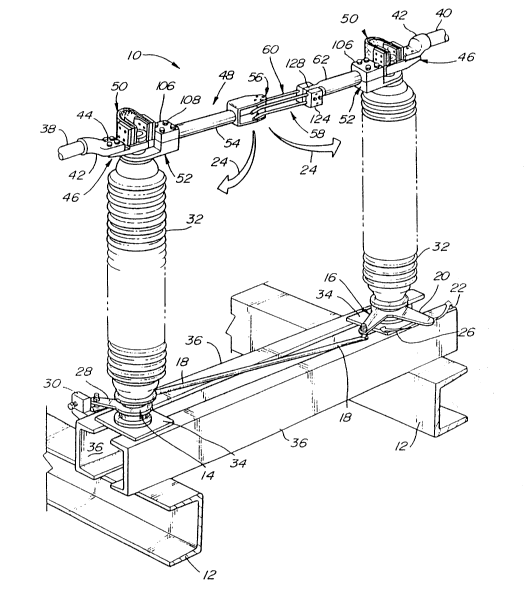
FIG. 1 is a perspective view of a center break disconnecting
switcll embodying the present invention showing the switch in its
~ closed position and indicating the direction of opening;
FIG. 2 is a top view Or the switch Or FIG. 1 sl-owin6 the
suitch in its closed position and showing how contact is
established during the closing mode;
21û93~3
FIG. 3 is an elevational vieu partiAlly in cross section taken
alon6 line 3-3 Or FIG. 2 showing the details Or construction Or one
the switch members including tl~e new bearing support Or this
-
n invention;
S g EIG. 4 is a cross sectional view taken along line 4-4 Or FIG.
2 sl~owing the dual contact establislled between a finger contact and
tl~e circumferential v-groove of a cylindrical spool contact;
FIG. 5 is an elevational view sl-owing the self aliFning
reature Or the finger contacts with the frusto-conical groove
contact, the misaligned contact finger being shown in phantom
berore it is brought into alignment;
FIG. 6 is a sectional view along line 6-6 Or FIG. 5 showing
7I the alignment Or the finger contact;
FIG. 7 is an exploded view of one of the rotating contact
members:
FIG. 8 is a view partially in section of one of the ringer
contacts showing tl~e interllal spring member and the external
conductor member-
Z FIG. 9 is a top view of a modified center break switch
. incorporating the invention:
FIG. 10 is a side elevation of the invention applied to a
vertical break suitch in uhich one of the two contacts is
~ stationary; and
-' FIG. 11 is an elevational view of a vertical break suitch
embodying the present invention with both contact bein6 rotating
- contacts.
SUMMAR~' OF THE: PRESE~TL'~' PREFERRrD EMBODIMENTS or TIIE INVENTlOII
c Referring to FIG. 1. the disconnecting switch 10 according to
~; the invention is shown as a center l>reak switch which is mounted on
superstructure 12. Superstructure 12 is normally the top beams of
an open frame structure in a-substation, which frame structure
houses various electrical components including circuit breakers and
21~9~3
tlle likc. The operating mechanism ror the switch includes rotatin~
levers 14 and 16 and connection links 18. When arm 20 of lever 16
is rotated in tlle direction Or arrow 22, the switch elements are
~ moved from the closed position shown to an open position in the
0 direction Or arrows 24. When the arm 20 Or lever 16 is rotated in
the direction Or arrow 26, the suitcl- elements are moved to the
illustrated closed position which may be established and limited by
arm 28 Or lever 14 acting a6ainst adjustable stop member 30. A
similar stop element (not shown) can be used to establish and limit
the open position of the switch.
Lever 20 will be tied into otl~er linkage and mechanisms whicll,
for example, can operate more than one switch simultaneously as for
three phase current. The operating mechanism which can include
~ I)and operated levers or motor driven devices are located at ground
level. The open and closed swi1c]l position limits may also be
located at ground level and can e]iminate the need for stop 30 and
lever arm 28.
Rotatable insulators 32 are suitably mounted througll platens
7 34 to a base sbown as formed by two cl-annel memhers 3G. It will be
2n appreciated tl)at the base and mounting details can be varied to
< suit the situation.
Inlet and outlet busses 38 and 40 are attached by connectors
42 ~ith bolts 44 to stationary switch terminal n-embers 46.
~ Current is carried rrom inlet bus 38 througll the first switch
member 48 by stationary terminal member 46, shunt 50. insulator
mountillg melober 52. suitch arm 54 and spool contac- 5fi. The
curlent is carried througl- s-itch n~ember 58 flom ringer contact 6
through switch arm fi2. insulatol mountin~ member 52 shunt 50 and
~ stationary terminal member 46 to outlet bus 40. The contacts can
be reversed witll the finger contact 60 being located on the rirst
5ujtch member 48 and tbe spool contact 56 being located nn tlle
second switch member 58.
21~)9353
Since t}le components are lbe same ror tle rirst nnd second
suitch lllembers or the left side switcll member and ~le right side
SWitcll member as seen in ~IG. 1 except for tlle conts3cts and
~ mounting to their respective arms the details of only tl-e spool
0 contact switcll member is shown in detail in FIGS. 3 and 7. Like
components for switch members 48 and 58 are numbered the same s3s
primarily seen in F]G. ~.
FIG. 3 shows tlle assembled bearing 64 of this invention which
includes spaced lower insert member 66 and upper insert member 68.
These insert members are made uith plastic resin having high
strength and lubricity properties under the extremes of ambient
temperature variation and weather conditions encountered in its
! outdoor use. A metal impregnated plastic such as a bronze
impregnated PTFE p]astic resin is prcrelrcd. ~ccro-Scsll ~-m~
Accrolon 801 compound uitll 55 bronze and 5% molybdenum disulphide
by weight blended in a PTFE base is a preferred bearing material.
The opposel rrusto-conical load bearing surfaces 70 and 7Z of
U inserts 66 and 68 are disposed at 45 to axis 74 Or the bearing
~ evenly distributing forces to keep tlle bearing 64 free running
2n . under combined tlrust and radial loading. The inserts are sized
C relative to the stationary terminal member 46 and rotatable
insulator mounting member 52 to be an insulator between the
c members uith the current being conveyed througllrlexible shunt 50.
L The bearing uill maintain integrity even with contact arcing heat
up and no external lubrication is required. Tl-is maintenance free
- bearinsOr is a vast improvement over conventional bearings even
those constlucted uith stainless steel ball bes~l-ing riding in
stainless steel races and having Teflon0 seals. These state of the
l~ art ball bearings are still subject to freezing in a closed
position due to melt down in a high electrical resistance current
path created by arcing and corrosion. Switcl- member 48 (and s~itch
member 58) witll its bearing 64 can be assembled by first attaching
210~3~3
flallFe 7G Or tlle insulator mounting member 52 to insulator flange
8 78 by bolts 8n. Lower hearing insert 6~ is slipped over bearinF
spindle &2 of the insulator mountinF member 52 to rest on shoulder
~ 84 of boss 86. Spind]e 82 is received in spindle hole 88 of switch
G terminal 46. Next the upper insert 68 is slipped over spindle 82
witll its conical load bearing surface 72 seating against chamfer
90. Finally retainer nut 92 is screwed on the threaded end 94 of
. spindle 82 to retain tlle member 52 for rotation relative to
terminal 46.
0 Spool contact 56 can be preassembled to yoke end 98 Or switch
arm 54 by bolts 100.
Switch arm 54 is placed in cradle 102 of the insulator
> mounting member 52 with its shunt mounting plate 104 being inuard
Or t~l~ c~ ok~ r~-t~ 1n~ is r~l~tcn~cl ~ ll( ln2 uill,
bolts 108 firml~ ancl-oring 5uitch arm 54 to the assemhly.
Shunt 50 includes a stack of thin silver plated copper strips
110 uhich are held at one end between mounting flange 112 of
terminal member 46 and mounting plate 114 b~ bolts the nuts 116 and
~ 118. Shunt 50 is mounted at its other end betueen shunt nounting
20 ~ flange 104 on suitch arm 54 and mounting plate 120 by bolts and
nuts 116 and 118. The use of stacked thin copper sheets 110 in
r shunt 50 provides the necessary flexibilit~ for movement of the
s~itch arm 54 relative to fixed terminal 46 but provides stiffl)ess
against bendin6 not supplied by a braided connection.
Suitch member 58 is assembled in the same manner as switch
melnber ~8 except tllat the spool contact 56 is replaced ~ith finger
contact 6n. Individual contact fingers 122 are held in mounting
^ Ilocks 124 b~ set screws 125 as best seen in ~IG. 5. Jhe free end
~ of switch arm 62 has a tongue 128 uhicll receive bolts 130 passing
tllrough a mounting plate 124 on both sides Or tlle tongue secured
~ith nuts 132 as seen in ~IG. 2. Referrin6 to ~IG~ n, tl~r
individual contact fingers 122 are formed ~ith an inner stainless
210~353
~ steel rod l34 wllicl~ serves as a spring element and an outcr copper
c tube ~3G wlicl acts as a conductor. The spring rod 134 extends
substantially the entire longitudinal lengtll 146 of the ringer
stopping sllort of tlle guide end 138 which is bent out~ardly at an
-
O angle between 30 and 60-. The stainless steel spring core is
preferably made with a non magnetic material such as 304 stainless
steel. Tlle copper tube is preferabl~ silver plated for minimum
contact resistance.
The generally cylindrical spool cont~ct mcmher 5G is formed
~itl) two ~-grooves 140 to present two abutting frusto-conical
contact surfaces 142 and 144 for each groove whicll makes contact
w
with individual fingers 122. Preferably the spool contact is
Z silver plated also for minimum electrical resistance.
~ It can be seen. particularly in reference to FIG. 2 tl-at with
lS the individual fingers 122 of finger contact 60 arranged Witll their
rree ends 138 divergillg outwardl~ from the axis Or su~itch arm 62
that the~ act as guides as the spool contact arm 54 and the finger
contact arms G2 of swjtcll members 48 and 58 are rotated to~ards a
closed position witll tlle fingers 122 engaging the circumferential
V-groove 140 of the spool contact 56. As the arms reach tl-e full~
< closed position of the switcll the spool is driven into the
longitudinall~ extending ~ortion 146 of the fingers 122 where the
full spring force exer1ed b~ in1ernal spring member 134 acts to
h erfect tuo point contact in eacl~ circumferential groove 140 namely
against ~otll frusto-conical surfaces l42 and 144. ~itll thc
prefelled allangemellt of a pair Or parallel fingers contact is
made on diametrical]~ opposi1e sides Or the spool providing four
r contacts per groove. In the illustrated s~itcll two V-grooves 140
~ are used providing eigllt points of contact witll four fingers as
seen in FIG. 4. The numler of grooves and fingers can be increased
as needed.
Moreover the circumferential V-groove 140 of spool contact 9G
21~3~
provides an aligning runction ror tlle fingers so that ir one Or the
finFers is bent out of alignment as shown in phantom at 122 in
FIGS. 5 and 6, one of the conical surraces 142 or 144 t~ l Fuide
~ the ringer into the groove and into full contact with both
0 surfaces.
c
The unique circumferential V-groove contact and the unique
finger contact uith its internal spring can be used in any Or the
conventional swi1ch constructions. Lik~wise the unique bearing
construction can be used uith any Or the rotating contact members.
A modification of the center break switch of FIG. 1 is shown
in FIG. 9 uhereill only one contact utilizes a switch arm with the
other contact being mounted directly on the rotatable insulator.
2 In particular, su-itch member 48 utilizes arm 54 to carry spool
: contact 56 uhereas the suitch member 58 mounts the individual
fin6els 122 on top of the insulator assembly. Both contacts are
still rotated as shoun.
In FIG. ~0 a vertical disconnecting switcll 150 is sl~o-wn witl
rin~er contacl ~.n mounted in a s1at;onary position on instlla1-lr 82.
~pool contact 56 is mounted on an arm 148 actuated by a mechanism
"o ~ 152 to suin6 in a veltical direction as indicated by an arrow 154.
Lower finger 156 is incleased length over upper finger 122 to
provide guiding the spoo] contact 56 after the arm 148 has been
rotated to the position shoun. Linkage 158 is pivoted in tlle
~ direction of arrol- lG0 to provide linear motion of contact 56 in
~5 tlle directiorl Or arrou 162 to move the spool conlact into the
- position shown at 56 .
FIG. 11 is a sho--ing Or anothel vertical l~reak switcll
c constructed in a fashiol1 rilllilar to the l-ori~ontal break switch
~ slloun in FIG. 9. Spool contact 56 is mounted at the end of suitcl-
arm 54, and ringer contact 60 is mounted for rotation directly oninsulator 3~.
It uill be seen rrom the description of the presently
2109353
preferred embodiments that the invention may be incorporated into
O many different switcll constructions with modification being made as
'D
needed. It will also be seen tl)at the construction provides easy
~ disassembly and replacement Or the eontacts. Set screws 126
o release individual finger contacts, and bolts 100 release the spool
contact. It will also be seen that the spool can be repositioned
from its installed position should pitting occur in the contact
surfaces 1~2 and 14i.
] claim:
" :
-
-
z
U
-
L
-
Q