Note: Descriptions are shown in the official language in which they were submitted.
~9~0 PATENT
550025-2020
NOI8E CANC~LLAT~ON APP~RAT~S
~AC~GRO~D OF T~}: INv}srlTIoN
~iol~l o~ t2~e ~nvent~ on
This invention relates to a noise cancellation
~pparatus and, ~ore particularly, to an apparatus for canceling
or reducing background acoustic noise for use with a telephone
handset or a boom microphone device or tbe like.
D~cription o~ t~e Prior Art
As is to be appreciated, in numerous situations, the
presencè of background acoustic noise is undesirable. As an
example, consider the situation in which an operator is
attempting to conduct a telephone conversation from a telephone
or such similar device located in a noisy area. In this
situation, loud acoustic background noise is received by a
~icrophone in the handset of the telephone and converted to an
electrical signal which is supplied to the telephone(s) of the
person(s) having the conversation with the operator and is
converted thereat to an acoustic signal. As a result, the person
to whom the operator is communicating constantly hears the loud
backqround noise. Further, when the person is speaking, such
spe~ch is combined with the background noise and, as such, may b2
difficult for the other person(s) to understand. As a result,
~he operator may have to shout into ~he microphone of the
telephone. Furthermore, the signal representing the background
noise is also suppli~d fro~ the microphone in the operator's ~ --
DS10:2020.APP
,.
,
2~ ~ ~ 4 ~ PA~ENT
550025-2020
handset to the speaXer in the operator's handset. Thus, the
operator also constantly hears the background noise from the
fpea~er in the operator's handset and, when the other person is
speaking, may impair the understandinq thereof.
As another example, consider the situation in which a
pilot who is operating a helicopter or the like wishes to
communicate with another person by way of radio f-equency (RF)
communication. In this situation, the pilot typically speaks
into a so-called boom microphone which is couple~ to a radio
transmitting/receiving device whereupon the speech is converted
into ~F signals which are transmitted to a second
receiving/transmitting device and converted therein to speech so
as to be heard by the other person(s). As with the above
situation of a telephone located in a noisy area, the loud
background noise ~rom the helicopter is received and converted
into an electrical signal by the boom ~i~rophone device and
thereafter supplied to the receiving device. As a result, the
person(s) communicating with the pilot hears the loud background
noise. This may be particularly annoying when the pilot leave~
the radio transmitting/receiving device in the "ON" position
while operating the helicopter.
In an attempt to reduce background noise 50 as to
i~prove per~ormance of a telephone or a boom microphone located
in ~ noisy environment or the like, pressure gradient microphones
~ay be utilized. Basically, a pressure gradient Dicrophone
DS10:2020 .AW
~1~9d4~ PATENT
550025-2020
responds to the difference in pressure at two closely spaced
points. When used in an environment where the pressure gradient
of the bac~ground noise is isotropic, the electrical signal
produced by the pressure-gradient microphone due to such
5 background noise is effectively zero. However, in most actual
situations, the pressure gradient of the background noise is not
isotropic and, as a result, in these situations, the performance
of the pressure-gradient microphone is adversely affected.
Additionally, since voice or speech propagates in more than one
direction, the electrical signal produced by the microphone ~hich
corresponds thereto is often degraded. Thus, even if a pressure
gradient microphone is utilized in either a telephone handset or
a boom microphone, the desired amount of background noise
cancellation may not be sufficient and the performance may not be
adequate.
Furthermore, since two opposite sides of a pressure-
gradient microphone respond to acoustic pressure, as previously ~;
mentioned, the handset of an existing telephone would have to be
substantiall~ modi~ied so as to enable these two sides o~ the
microphone to respond to the acoustic pressure. Moreover, as a
result of u6ing such a microphone in a telephone handset, the
electrical signals produced therefrom should be amplified. Thus,
to replace the conventional microphone in a telephone handset of
nn existing telephone with a pressure-gradient microphone would
DS10:2020.APP 3
2,ln9~o
PATENT
550025-2020
typically necessitate replacing the handset with a new handset
and, ~s ~uch, would be relatively expensive.
As an alternative to using pressure-gradient
~icrophones, an acoustic feed-back type syste~ may be utilized.
Such a system normally includes compensation filters which are
used to equalize the transfer function of the speakers. Since
the characteristics of the speakers are tightly controlled by
these filters, the cost of the filters is relatively high. As a
result, such acoustic feed-back systems are typically relatively
expensive.
Thus, the prior art has failed to provide a relatively
low-cost means for reducing bacXground noise to an accepta~le
level for use with telephones and/or boom microphone devices or
the like, and a cost-effective means for enabling existing
telephones to reduce background noise to an acceptable level.
OBJ~CT8_AND S~MMARY OP T~ INVENTION
An object of the present invention is to provide noise
reduction apparatus which overcomes the problems associated with -~
the prior art.
~ore specifically, it is an object of the present
invention to provide noise reduction apparatus which reduces
background noise to an acceptable level.
Another object of the present invention is to provide
noi~e reduction apparatus as aforementioned for use with a
telephon2 or boo~ ~icrophone device or the like.
DS10:2020.AP$' 4
9~
PATENT
550025-2020
It is still another object of the present invention to
provide noise reduction apparatus as aforementioned which is
r~lativçly inexpensive.
It is yet another object of the present invention to
provide a relatively low-cost noise reduction apparatus for use
with telephones which is operable with standard available on-line
power.
A still further object of the present invention is to
provide a relatively low-cost noise reduction apparatus which is
readily adaptable to handsets of existing telephones and which is
operable with standard available on-line power.
A yet further object of the present invention is to
provide a relatively low-cost noise reduction apparatus Por use
with telephones or which may be readily adaptable to handsets of
existing tel~phones which enables an operator to selectively
amplify a received signal.
In accordance with an aspect of this invention, a .
telephone handset apparatus for use with a telephone operable by
standard powsr supplied to t~e telephone handset for transmitting
and receiving signals representing speech between two or ~ore
operators is provided. The apparatus includes a housing haviny a
first microphone means for receiving a first acoustic signal
co~posed of speech from the operator using the appara~us and
,~ackground noise in the vicinity of the speech and for convexting
the first acoustic ~ound to a first signal, and a s~cond
D;10 :2020 .~PP 5
' ~ , . ' :
2~o94~7~2173~18
microphone means arranged at a predetermined angle with respect
to the first microphone means for receiving a second acoustic
sound composed of substantially the background noise and for
converting the second acoustic sound to a second signal; and a
device for subtracting the second signal from the first signal ~`
so as to obtain a signal representing substantially the speech.
Other objects, features and advantages according to
the present invention will become apparent from the following
detailed description of the illustrated embodiments when read
in conjunction with the accompanying drawings in which corres-
ponding components are identified by the same reference numerals.
BRIEF DESCRIPTION OF THE DRAWINGS
:
Fig. 1 illustrates a telephone having a noise reduction
apparatus according to an embodiment of the present invention;
Fig. 2 is a block diagram of the noise reduction
apparatus used in the telephone of Fig. 1;
Fig. 3A is a front plan view of the receiver portion
of the telephone of Fig. l;
Fig. 3B is a cross-sectional side view of the receiver
portion of the telephone of Fig. 1 with the cap removed;
Fig. 4 is a schematic diagram of the block diagram of
Fig. 2;
Fig. 5 is another schematic diagram of the noise
reduction apparatus illustrated in Fig. 2; and
Figs. 6A, 6B and 6C illustrate a boom microphone
device utilizing a noise reduction apparatus according to an
embodiment of the present invention.
..: `
9 4 ~l~ 72173-18
DETAILED DESCRIPTION OF THE PREFERRED EMBODIMENTS
Fig. 1 illustrates a telephone 8 which utilizes a
noise reduction apparatus in accordance with an embodiment of
the present invention. As shown therein, the telephone 8
generally includes a handset 10, having a speaker portion 41 and
a receiver portion 42, and a telephone unit :L8 which may be
coupled therebetween by way of a telephone cord 30. Alternatively,
the telephone may be a cordless type telephone and, as such, the
handset 10 is coupled to the telephone unit 18 by way of RF
waves. The receiver portion 42 includes first and second
microphones 12 and 14, respectively, (Fig. 2), a switch 40 for
adjusting the volume of a signal supplied to the speaker portion
41, and a cap 48 having a recessed portion 44 and a mesh portion
46.
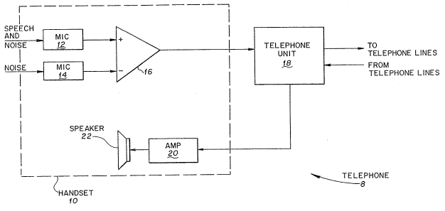
Fig. 2 illustrates the telephone 8 in block diagram
form. As shown therein, the handset 10 generally includes first
and second microphones 12 and 14, respectively, a subtracting
device 16, which in a preferred embodiment is an operational
amplifier ("op-amp"), an amplifier 20, which is preferably an
op~amp, and a speaker 22. The first and second microphones 12
and 14, respectively, op-amp 16 and amplifier 20 are preferably
contained within the receiver portion 42 (see Fig. 1).
,
', ~ . '.' , , ~' '' - ~ , ,
.. ..
.
~1 ~944~ PATENT
550025-2020
Acoustic signals composed of speech or the like and
background noise are supplied to the first mlcrophone 12 and
converted therein into a corresponding electrical signal which is
thereafter supplied to the plus terminal of the op-amp 16. The
background noise is supplied to the second microphone 14 and
converted therein into a corresponding electrical signal which is
thereafter supplied to the ~inus terminal of the op-amp 16. The
op-amp 16 is adapted to subtract the noise signal from the second -
microphone 14 from the speech and noise signal from the first
microphone 12 and to supply therefrom an electrical signal
representing substantially the speech to the telephone unit 18
whereupon the speech signal is transmitted therefrom through the
telephone lines to a desir~d telephone or tel.ephones. The output
signal from the op-amp 16 is also combined in the telephone unit
18 with a received signal from the telephone lines and supplied
to the amplifier 20. The op-amps 16 and 17 are preferably
relatively low-power integrated circuits (IC's), such as
complementary metal oxide semiconductors ~CMOS), and may be
constructed from either one or more CMOS IC chips. Although not
20 shown in Fig. 2, amplifier 20 may be selectively set by use of
the switch 40 (Fig. 1) by the operator so as to adjust the
amplification of the received signa} to a desired level, The
aopli~ied ~ignal from the amplifier 20 is supplied to the speaker
22, whereupon the amplified signal is converted into an acoustic
~ignal 50 as to be heard by the operator.
DS10:2020.APP 8
~1 ~94~0
PATENT
s50025-2020
Figs. 3A and 3B illustrate two views of the receiving
portion 42, in which the cap 48 is removed in the view of Fig.
3A. As shown therein, the receiving portion 42 generally
includes a housing 74, a circuit board assembly 78, the first and
~econd microphones 12 and 14, respectively, and the cap 48. The
~irst and second microphones 12 and 14, respectively, which are ~ :
preferably electret microphones or similar such microphones, are
arranged or positioned as hereinafter described. These
microphones are held in place or secured by a holding member 76
wh~ch, for example, may be constructed of a foam-like material,
which, in turn, is secured to the housing 74. The respective
outputs from the first and second microphones 12 and 14 are
supplied through respective wires (not shown) to the op~amp 16
which is contained on the circuit board assembly 78 which, in
turn, is attached to the housing 74. As hereinafter more fully
described, the circuit board 78 may contain additional circuit
elements for processing the signals received fro~ the first and
second microphones and for amplifying si~nals for supply to the
speaker 22 (Fig.2). A cover 72 may be utilized which is attached
to the hou~ing 74 by use of ~dhesives or the liXe or
alternatively may be sonically welded together. The cover 72 and
the hou ing 74 with the circuit board assembly 78, holding member
76 and the first and second microphones 12 and 14 form an
~sembly 71.
DS10:20ZO.APP 9
' ' '' ' ~ '' `
~09~40 pATENT
5s00z5-2020
The cap 48, which may be constructed from a plastic-
type material such as polycarbonate, includes an annular side
~ beir 43 and a portion 45 having a typical thickne~s T which is
coupled to the side member 43 and arranged so as to be lower than
the upper portion of the side member by a minimum predetermined
a~Sount such as 0.020 of an inch, thereby creatins a recessed
portion 44. The portion 45 includes a portion 46 having a
thickness T' which is less than the thickness T and which has a
plurality of through holes contained therein and may resemble a
mesh-like portion. In a preferred embodiment, the thickness T'
of the portion 46 has a thickness of less than 0.030 of an inch.
Since the portion 46 represents a relatively small a~ount of the
portion 45, reducing the thickness therein does not adversely
affect the overall structural rigidity of the cap 48.
Alternatively, the portion 46 may be constructed from a stronger
material, for example, stainless steel or such similar material,
and combined with the portion 45. As is to be appreciated, ~y
arrangin~ the portions 45 and 46 so as to be recessed from the
upper portion o~ the side member 4~3, even when the receiver ::
portion 42 is placed on a surface, the side member 43, and not
the portions 45 or 46, contact such surface. As a result, any :~-
loads are not directly impacted on the portion 45 and/or the : -
-
portion 46, but are instead delivered to the side member 43.
The cap 48 is positioned over the asse~bly 71 so that ;~
the first and second microphones 12 and 14, respectively, are -~
D510:2020.APP 10
-: . :
21 09~0 PATENT
550025-2020
arranged below the portion 46 with the first microphone
positioned relatively close to the underside of the portion 46
Thus, the speech travels a relatively short distance from an
operator, who is speaking into the receiver portion 42 from a
S distance of preferably less than 1 inch, through the portion 46
to the first microphone. As a result, acoustic ~istortions are
minimized.
The arrangement of the first and second microphones 12
and 14, respectively, within the receiver portion 42 is
illustrated in Figs. 3A and 3B. More specifically, as shown in
Fig. 3B, the first and second microphones are arranged so as to
have an angle 0 therebetween, which preferably has a value in a
range bQtween 30 and 60. The first and second microphones are
further respectively arranged so as to have an angle e and [(gO-
e) + o] between a plane parallel to the receiving or "sensitive"surface of the first microphone 12 and the direction of speech
from an operator, and an axis normal to the sensitive surface of
the second microphone 14 and the direction of speech, as shown in
Fig. 3~; and so as to have an angle ~ between the direction of
~peech and the second microphone, as shown in Fig. 3A. In a
preferred e~bodiment, the angle e has a value of less than
approximately 35 and the angle ~ has a value of approximately
180. As a result of arranging the first and second microphones
~n this manner, the ~irst ~icrophone 12 receives both the speech
from the operator and the background acoustic noise which is
DS10:Z020.~
'', .,:, : ~''
21~9~4~ PATENT
550025-2020
present in the vicinity, and the second microphone 14 essentially
receives only the same background acoustic noise which is
r~ceived by the first microphone.
Although, as previously mentioned, the angle 0 has a
value which is preferably between 30 and 60, the first and
second microphones 12 and 14, respectively, may nevertheless
operate satisfactorily even if arranged so as to have an angle 0
which lies outside this range. However, as the angle 0 becomes
substantially smaller than 30 or larger than 60, the
performance may be adversely affected. That is, when the angle 0
becomes substantially smaller than 30, the second microphone 14
receives both the speech and background noise. As a result, upon
subtracting the output signal of the second microphone 14 from
the output signal of the first m~crophone 12, a portion or all of ~ ~
the speech may be canceled. On the other hand, when the angle 0 ~:
is substantially larger than 60, the background noise received
by the second microphone 14 may not be similar to that received -~
by the first microphone 12. As a result, subtracting the output -
siqnal of the second microphone 14 from the output signal of the
first microphone 12 may not adequately cancel the background
noise received by the first ~icrophone.
In a like manner, although the angles ~ and ~ have ;
preferred values of less than 35 and approximately 180, -~
raspectively, as previously ~e~tioned, the first and second
nicrophones may operate satis~actorily even if arranged so as to -~
DSl0:2020.APP 12 .. ~
: ~ :
~1 09~40
PATENT
550025-2020
present in the vicinity, and the second microphone 14 essentially
receives only the same background acoustic noise which is
r~ceived by the first microphone.
Although, as previously mentioned, the angle 0 has a
value which is preferably between 30 and 60, the first and
~econd microphones 12 and 14, respectively, may nevertheless
operate satisfactorily even if arranged so as to have an angle 0
which lies outside this range. However, as the angle 0 becomes
substantially smaller than 30 or larger than 60, the
performance may be adversely affected. That is, when the angle 0
becomes su~stantially smaller than 30, the second microphone ~4
receives both the speech and background noise. As a result, upon
subtracting the output signal of the second microphone 14 from
the output signal of the first microphone 12, a portion or all of
the speech may be canceled. On the other hand, when the angle 0
is substantially larger than 60, the background noise received
by the second microphone 14 may not be similar to that received
by the first microphone 12. As a result, subtracting the output
signal of the second microphone 14 from ~he output signal of the ~-
first ~icrophone 12 may not adequately cancel the background
nois~ received by the first microphone.
In a like ~anner, although th~ angles ~ and ~ have
preferred values of less than 359 and approximately 180,
respectively, as previously mentioned, the first and second
~5 microphones may op~rate satisfactorily even if arranged so as to
OS10:2020,APF~ 12
:, ` ~, :
,: , : .
' "' ` ' ;"
21~9440
PATENT
550025-2020
have different values of these angles. However, as th~ values of
~he angles ~ and ~ become substantially different from the
respective preferred values, the performance may be adversely
~ffected. That is, when the angle ~ becomes substantially larger
than 35 , the second microphone 14 may receive both the speech
and background noise. Similarly, when the angle ~ is
substantially smaller or larger than 180, the second microphone
14 may receive both the speech and background noise. As a
result, in either of these situations, upon subtracting the
output signal of the second microphone 14 from the output signal
~E the first microphone 12, a portion or even all of the speech
may be canceled.
As is to be appreciated, by using the above-described ~ ;
devices and materials for the components of the receiver portion
42, the cost for constructing such receiver portion is relatively
low. Further, by using CMOS chips, as previously described, the
power consumption of the receiver portion is kep~ relatively low.
As a result, the receiver portion may be powered by the standard
power available in the handset and, as such, does not require
additional power or transformers or the like. Furthermore,
although the receiver portion 42 has been described for assembly
with the handset 10 of the telephone 8, which is a new telephqne~
such r~ceiver portion, or a slight variation thereof, may be used
ln handsets of existing telephones. ~hat is, in this latter
situation, the cap and microphone contained within the handset of
DglO:2020.APP 1 3
4 0
PATENT
550025-2020
an existing telephone are merely replàced with the receiver
portion 42. Thus, such use of the receiver portion 42 provides a
rolatively easy and low-cost means to modif~ a handset of an
` ~xisting telephone to include the present noise reduction
apparatus.
Fig. 4 illustrates a schematic diagram of one circuit
arrangement of the telephone 8 shown in Figs. 'L and 2. As shown
in Fig. 4, the first microphone 12 is coupled through a resistor -
202, which is adapted to function as a current limiting resistor
so as to correct the bias of an output ~rom the first microphone,
to an input terminal 200. The first microphone 12 is further
coupled through a resistor 210 to the plus terminal of the op-amp
16 and through a resistor 212 to a variable resistor 214. The
sacond microphone 14 is coupled through a variable resistor 208,
which is adapted to function as a current limiting resistor so as
to correct the bias of an output of the second microphone, to an
input terminal 201, and to the minus terminal of the op-amp 16.
The limiting resistor 208 is preferably a variable current
limiting resistor which enables the level of the output signal
from the second microphone to be matched to within a
predetermined value to the level of the output signal of thP
first ~icrophone 12. More specifically, the limiting resistor
208 enables the output signal of the second microphone 14 to be
weighted such that when a signal havin~ a similar level is
outputted from the first microphone 12, the amplitude of the
DS10:2~.APD 14
.
: ,
.. .. . ' . ' . ,, ~ ; ~ ' . .' ~
~,109440 PATENT
550025-2020
di~f~irence therebetween is minimized. The value of the current
limiting resistor 208 can be selected according to minimization
criteria. An input terminal 198 is connected to resistors 204
~nd 206, which are adapted to divide the voltage received at the
~nput terminal 198, and to the minus terminal of the op-amp 16.
The output of the op-amp 16 is coupled to capacitors 220, 222 and
226 and resistors 224 and 228 which, in turn, is connecte,i to a
nmicrophone input" terminal of the telephone unit 18. The output
: -:
from the op-amp 16 is further coupled through a variable resistor ~- -
214, a resistor 216 and a capacitor 218 to ground. Resistors ~ ~-
210, 212 and 216 and variable resistor 214 provide variable gain, ~
.
for example, 20 to 1 amplification, to the output o~' the op-amp
16. 'I'he capacitors 218, 220 and 222 are adapted to remove
residual dc (direct current) levels which may be present in the
output signal from the op-amp 16. The resistors 224 and 228 and
the capacitor 226 are adapted to function as a low-pass filter
having a break point at a predetermined value which, for example,
may be 3.7 ~Hz.
Th,a t~lephone unit 18 is further connected to the
telephone lines and i5 adapted to receive signals through the
~icrophone input ter~inal and to supply these signals to the
desired teilephone or telephones by way of the telephone lines.
'The telephone unit 18 is further adapted to receive signals from
anothier telephone or telephones by way of the telephone lines and
to co~bine such signals with thiose received through the
DS10:2020.APP 15
. ~
,`
. ~ : , , ,~ " , . . ..
Z1~9~4~
PATENT
550025-2020
~ microphone input terminal, as previously described, and to supply
.~ ~he combined signal to a speaker input terminal 231. ~he input
.~ torminal 231 is connected through a capacitor 230, which is
.' ~dapted to block dc signals, and a resistor 232 to the minug
terminal of an op-amp 17 and through a resistor 234 to a variable
resistor 240. An input terminal 199 is connected to the plus
terminal of the op-amp 17. The output from the op-amp 17 is
connected through capacitors 242 and 244 and a resistor 246 to
the speaker 22. T~e output from the op-amp is further connected
through the variable resistor 240, a resistor 238 and a capacitor
236 to ground.
` The operation of the telephone 8 shown in Fig. 4 will
now be described below.
Upon activating the handset 10, by lifting the handset
~`;; lS 10 from the switch hook (not shown) or the like, standard
telephone line voltage is applied to input terminals 198, 199,
~` 200 and 201. A signal fro~ the first microphone 12, which has
~,i been bias corrected by the current limiting resistor 202, is
~` supplied through the resistor 210 to ~he plus terminal of the op-
~` 20 amp 16. An output signal from the second microphone 14, which
has ~een bias corrected by the current limiting resistor 208, is
~r supplied to the minus terminal of the op-amp 16. The op-amp 16
~ubtracts the signal received from the second microphone 14 from
that received from the first microphone 12 and outputs the
2S resulting subtracted signal. DC levels which may be present in
~Sl0:2020.API> 16
'
~-~
. :
st,
~, , . ~ ` -
21 0 9 ~ ~ O PATENT
550025-2020
the output signal are removed and the signal is amplified. High
~requency signals, such as those over 3.7 kHz, are then removed -~
fro~ the amplified output signal and the resulting signal is
; upplied to the telephone unit 18. Thus, a voltage signal is ~ -
supplied to the telephone unit 18 which is proportional to the
difference between the voltages generated by the first and second
~icrophones 12 and 14, respectively.
An output signal from the telephone unit 18, which is a -~
combination of the signals received through the microphone input -~ ~
10 terminal and the telephone lines, is supplied to the input -
terminal 231 of the amplifier 20. The signal from the input
terminal 231 is supplied to the capacitor 230 so as to remove any
dc signals which may be present. The output from the capacitor
230 is supplied through the resistor 232 to the minus terminal of
` 15 the op-amp 17. The op-amp 17 subtracts the signal from the : -
telephone unit 18 from the signal received from the input
terminal 199 and supplies a subtracted signal therefrom. Such
signal may be selectively amplified, through the use o~ resistors ;
232, 234 and 238 and variable resistor 2~0, by the operator by
use of the switch 40 (Fig. 1). Any dc signals which may be
present in the amplified signal are thereafter removed by the
; capacitors 242, 244 and 236. The output signal from the
capacitor 244 is current li~ited by the resistor 24~ and is
thereafter supplied to the speaker 22 so as to be converted
thereat into an acoustic signal.
DS10:20ZO.APP 17
: ;
- , , , ,. . , . , .. , " . ;, , .
, . . , ~ :
~1~9~
PATENT
550025-2020
Fig. 5 illustrates an alternative arrangement for
processlng the signals obtained from the first and second
~$crophones 12 and 14, respectively, so as to provide a current
- output for supp}y to the telephone unit 18 which is proportional
5 to the difference of the voltaqes generated by the first and
second microphones.
More specifically, the circuit arrangement of Fig. 5
includes a handset 10' having a plurality of input terminals 300,
301, 370 and 390 which are each adapted to receive standard
available on-line power. The first microphone 12 is coupled
' through a current limiting resistor 302 to the input terminal 300
and is further coupled to the plus terminal of a subtracting
device 316, which is pre~erably a CMOS op-amp. The output from
the second microphone 14 is coupled through a variable current
limiting resister 308 to the input terminal 301 and is further
~oupled to the minus terminal of the op-amp 316. The signal -
outputted from the op-amp 316 is supplied through filtering
- stages 350 to the minus terminal of a subtracting device 351
which is preferably a CMOS op-amp. The filtering stages 350 are
adapted to provide a predetermined frequency response
characteristic such as a signal roll off at a predetermined
frequency. As is to be appreciated, although two filtering
stages are ~hown in Fig. S any number of ~iltering stages may be
utilized. The input terminal 390 is coupled to resistors 392 and
, 25 394, which are adapted to reduce the signal supplied thereto, and
Dsl0:2020.~PP 18
.` ' , .
. ~
- , , , ; ,: ~, ~ : , , : :
t
h 10 9 4 ~1~ PATENT
550025-2020
to the plus terminal of the op-amp 351. An output signal from
. the op-amp 351 is supplied to the base of a transistor 366. The
input ter~inal 391 is connected to a Zener diode 360, a capacitor
. ,
362 and a resistor 364 which, in turn, is connçcted to the
. S collector of the transistor 366 and to the microphone input
terminal of the telephone unit 18. The emitter of the transistor
366 is coupled through resistors 367 and 368 to the minus :~
terminal of the op-amp 351 so as o provide a ~eedback loop
~` thereto. The op-amp 351 and the associated components provide -~
electrical isolation between the filtering stages 350 and the
transistor 366. The transistor 366 is adapted to amplify the
signal supplied to the telephone unit 18.
~; The output from the telephone unit 18 is coupled to the
input terminal 231 ~Fig. 4) and is thereafter processed in the
manner previously described with reference to the handset 10 of
Fig. 4 so as to provide an acoustic signal from the speaker 22.
The operation of the telephone 8' will now be described
b~low.
Upon applying power to the handset 10', by lifting the
handset ~rom the switch hook (not shown) or the like, standard
~` telephone line voltage is applied to input terminals 300, 301,
,` 370, 390 and 391. A signal from the first microphone 1~, which
' haQ been bias corrected by the current }imiting resistor 302, is
~upplied to the plus terminal o~ the op-amp 316. An output
25 - oignal from the second microphone 14, which has been bias
S DS10:2020.APP 19
:
., .
',
? : . . :
21~9~0 PATENT
550025-2020
corracted by the current limiting resistor 308, is supplied to
the minus terminal of the op-amp 316. The resistor 308 i5
pre~erably a variably current limiting resistor which enables the
l~vel of the output signal from the second microphone 14 to be
matched to within a predetermined value to the level of the
; output signal of the first microphone 12, in a manner
substantially similar to that previously described for resistor
208. The output difference signal from the op-amp 316 is
provided though the filtering stages 350, which may include one
or more RC networks or equivalent circuits, so as to limit the
upper frequency of the output signal to a predetermined value
which, for example, may be 3.7 kHz. The output signal from the
~iltering stages 350 is supplied to the minus terminal o the op-
amp 351 and a voltage signal from the input terminal 390, which
` 15 has been divided to a predetermined value such as one half
` thereof, is supplied to the plus terminal of the op-amp 351
which, in turn, calculates the di~ference therebetween and
supplies a corresponding output signal to the base of the
transistor 366. The voltage from the input terminal 391 is
supplied through the resis~or 364 to ~he collector of the
transistor 366. As a result, an amplified signal is supplied
from the handset 10' to the telephone unit 18 for supply
i t~erefrom through the telephone }ines to the desired telephone(s)
nd for combining with a received si~nal from the te}ephone(s)
.
DS10:2--0.AW 2 0
~ .
- ` 21~944~ ~
PATENT
550025-2020
for 8Upply to the input terminal 231 in a manner similar to that
previously described with reference to Fig. 4.
The individual circuit components wit:hout reference
d~signations depicted in Figs. 4 and 5 are connected as shown and
will not be discussed further, since the connec:tions and values
~re apparent to those s~illed in the art and are not necessary
,~ for an understanding of the present invention.
i Figs. 6A, 6~ and 6C illustrate a boom microphone 100
which utilizes a noise cancellation apparatus in accordance with
an embodiment of the present invention. More specifically, the
boom microphone 100 generally includes a housing 174, a circuit
board assembly 178, first and second microphones 112 and 114,
respectively, and a portion 147. The housing 174, which may be
constructed from either a plastic-like or metal-type material,
includes a circular portion 108 having a hole therethrough so as
~,~ to enable a shaft 106 to be inserted therein. As a result, the
` boom microphone 100 may rotate about the shaft 106 as illustrated
-` in Fig. 6A.
The first and second microphones 112 and 114 are
respectively coupled to the circuit board assembly 178 by wires
102 and 104. Tha circuit board assembly 178 contains circuitry
similar to that on the circuit board assembly 78 which, as
- previously described, processes the signals from the first and
~econd microphones 12 and 14, respectively, for supply to the
telephone unit 18 and, as such, in the interest of brevity, will
j~ DslO:20Xl.APP 21
! '
i;` :
. .' . .
21~9~40
, PATENT
550025-2020
not be further described herein. Therefore, the circuit board
aA~embly 178 is adapted to receive a speech and bac~ground noise
~ignal from the first microphone 112 and to subtract therefrom
the background noise signal from the second microphone 114 so as
to derive a signal which represents substantially the speech.
Such signal is supplied to a transmitting device (not shown) so
as to be converted to a RF signal and transmitted to a remote
receiving device (not shown). The first and second microphones
112 and 114, respectively, are held in place by a holding member
176 which, for example, ~ay be constructed of a foam-like
material. A mesh~ e screen 146 which, for example, may be
fabricated from a plastic-type or a metal mat~rial or the like,
is attached to the cut away portion 147 so as to protect the
; first and second microphones. The mesh 146 has a predetermined
~ 15 thicknQs~ which, for example, may be approximately 0.030 or less
`i, of an inch.
The first and second microphones 112 and 114,
respectively, whieh may be electret microphones, are arranged in
~! a ~anner similar to that of the pr~viously described first and
.
second microphones 12 and 14, respectively, of the handset 10.
That is, the first and second microphones 112 and 11~, are
~` r~spectively positioned so as to have an angle e~ and [(9o-e~) +
,~ o'~ between a plane parallel to the receiving or sensitive
urface of the first ~icrophone and the direction of speech from
an operator, and between an axis normal ~o the sensitive surface
D510:2020.~PP 22
?,
9~40
PATENT
550025-2020
of the second microphone and the direction of speech, as shown in
Fig. 5A. Further, the first and second microphones 112 and 114,
respectively, are arranged so as to have an angle 0'
therebetween, which has a preferred value in a range between 30O
and 60. The first and second microphones 112 and 114,
respectively, are located in relatively close proximity to the
~esh 146 and the cut away portion 147 of the housing 174 so as
not to receive acoustic sounds which have ~een unacceptably
distorted.
Although the above embodiments have been described as
having only one first microphone 12 (112) and one second
microphone 14 (114), the invention is not so limited and any
number of microphones may be utilized for the first microphone
and/or the second microphone. For example, a receiver portion
42' (not shown) may be configured which includes two or more
microphones operating as a first microphone 12' (not shown) and
two or ~ore microphones operating as a second microphone 14' (not
shown). In this configuration, when using multiple microphones
for the first and/or second microphones, respective variable
current limiting resistors are preferably provided for all but
one micropho~e for the first microphone 12' and for all
microphones for th~ second ~icrophone 14'. Thus, the outputs
from the first and second microphones, 12' and 14', respectively,
would comprise a weighted sum of several such microphone output
voltages. The current limiting resistors are preferably set to
DS10:2020.APP 23
.
,
~:
:' . .
`` ~109~40
PATENT
550025-2020
respective values so as to minimize some functlonal of the
l~ diff~rence of the first and second microphones 12' and 14',
respectively. The criterion for selecting the values of the
current limiting resistor or equivalently the weighting function
Y'
of ~ach microphone could be selected according to any well known
gradient search algorithm, so as to minimize the functional.
Further, although the above-described embodiments of
the present inventisn have been described for use with telephone
handsets and boom microphones and the like, the present invention
is not so limited and may be used with numerous other devices
such as intercom systems and so forth. Additionally, the present
1`
invention ~ay be used with processing devices operating in
,!' accordanc~ with predetermined processing algorithms, as described
i`l in U.S. Ratent Application Serial No. 07/887,500 filed May 22,
1992, which has a common assignee with the present application,
and which is hereby incorporated by reference.
Furthermore, although preferred embodiments of the
present invention and modifications thereof have b~en described
in detail herein, it is to be understood that this invention is
not limited to those precise embodiments and modifications, and
~ that other modifications and variations may be affected by one
i ~killed in the art without departing from he spirit and scope of
~ th~ invention as defined by the appended claims.
.:
;~
DslO:2020.. ~PP 2 4
~`
~- ~
,`. ,
, ...