Note: Descriptions are shown in the official language in which they were submitted.
W092/1916f ~ PGT/US92/03900 '~r
1
INZ~JBATION DEVICE
The present invention relates to intubation
devices and, more particularly, to a device and method for
inserting and checking the placement of an endotr_acheal
tube in a patient.
Certain types of illness and injury can cause a
patient s airway to become blocked or otherwise impaired,
preventing adequate oxygenation and ventilation of the
patient. When this occurs, prompt. corrective action must
be taken. Often times, this action requires the placement
of an endotracheal tube in the patients trachea in 'order
to restore or maintain an adequate airway. The process of
inserting the tube in the~patient is commonly referred to
as intubation.
Over the years, various types of intubation
devices have been developed for inserting endotracheal
tubes ;in a .patient. Perhaps the most'commonly used
~intubationtechnique is a process~~known. ae direct
laryngoscopy: - .:. t:In this technique, a device called a
laryngoscope is used to actually visualize- the upper
airway through the patients mouth during the process of
inserting the ~otracheal tube: This technique is
usually~successful,in ensuring correct placement.of the
. , . .. "tube-f: in,~,moat:~.patients. , However., ~., direct :~laryngoscopy
is
;i ~ ; -,: . ...not v:feasible;under~sall~. circumstances:>~~~Indeed,
rperforming
t~=.=~ intubation one a=.~~~relaxed,~.:well-prepared patient in a
30r hospital setting -is much different than attempting to
ntubate::ran accident victim in a moving ambulance,
helicopter or : on the street itself : ~~~.~;Moreover, direct
r
laryngoscopy can have the disadvantage of increasing the
risk; of: -.. dental . and ~ soft tissue trauma under certain
35:~circumstances.
W092/19169 ~~'1'..'x~ ~ PCT/U592/03900 ,r,r
> _..~
~~.1a9~0'~
When intubation is properly performed,
regardless of the procedure employed, the inserted end of
the endotracheal tube will be positioned in the patient's
trachea at a location substantially between the patient's
vocal cords and caring. This location has been found to
provide the best and most reliable airway management for
several reasons. Tf the tube is not inserted far enough
past the vocal cords, for example, it can become dislodged
and ineffective, such as when it ends up in the esophagus.
If the tube is inserted too far into the trachea, however,
past the caring, then the tube may only function to
adequately ventilate one of the lungs, instead of both.
This can lead to serious complications of its own. Thus,
proper placement of the inserted end of the tube plays a
mayor role in the intubation process.
V;~rious techniques have been used in the past to
attempt to ensure that the endotracheal tube lies in the
proper location between the patient's vocal cords and
caring at: the end of the intubation process. One such
w_.. .:,.technique involves placing a light at~the~inserted end of
H .the endotracheal tube. prior to intubation~. The'technique
s
is based on the principle of transillumination, that a
strong light can be transmitted through the cartilage and
soft tissues of the neck. It was further discovered that
.._... ~ when :the .light at the ~ end of the tube was clearly visible
... , ,
~~°~~. hrough°. the~:'.patient~s:v skin in vthe : area;:t:of
the'-=~sternal
.,
. ~ '-~r, p ~_notch, ...then, vthe ~insertad end of ~ the tube was v
approximately
~: c::~. halfway:. between.:v:tlle~.~~:-vocal v-cords and caring ~'in most
;~->30~:: patients. - :The absence of ~a :clear glow of illumination in
. ~::::frax~.' this area. usually indicates incorrect placement; : such as
~. ~-~ ~ 4:: in -:the resophagus ,. ; ~ ; ~ ...., ~f : . . .. _ 5 °j .
r~:.- ~ ~., ,.
Eventually, so-called lightwands were developed
for use in the intubation process. Early lightwands
comprised either a rigid or flexible-.copper wire with a
battery at one end and a light at the other. When a rigid
WO 92/.19169 ' ' . , ' PGT/US92/03900 '
.,; z:i~9~o~ 3
wire was used, it functioned as a stylet to stiffen and
guide the tube into the trachea. The flexible wire
typically has been used for nasotracheal intubation.
Later lightwands were somewhat more sophisticated but not
different in function. _ .
While the development of the lightwand has been
helpful in visualizing the airway during intubation and
ensuring proper placement of the tube, the intubation
technique still suffers from certain disadvantages. For
example, sometimes the lightwand will become jarred or
bumped during intubation and move from its position at the
end of the tube. In these circumstances, the intubation
procedure must be aborted and restarted, with the light at
the proper location.
Moreover, once the lightwand is withdrawn from
the tube after correct placement, there has been no
reliable way to recheck the position of the tube at a
l CO
d-tid
e
later time. Z
a
n
It has been known to use
.. measurements to monitor proper ventilation in an attempt
. to confirm, without visual evidence, that the tube is
still in the trachea and not the esophagus: However, end-
tidal COZ equipment may not
be readily available, and
patients in shock or in cardiac arrest may not be good
candidates for qualitative measuring devices.
additionally, end-tidal C02
measurements usually cannot
detect right mainstem bronchial position, which can be a
significant coyplication.
Other problems with known lightwands include the
fact that the lights are directed in a forward manner such
that the light tends to shine into the airway, rather than
' toward the patients sternal notch. This makes the light
difficult to see, unless the procedure is conducted in
relatively low light conditions. This is especially true
when intubation is being performed in bright sunlight,
g
WO 92/19169. v.~; '~~ ~ PGT/US92/03900" "
2109507
4
despite attempts to shield the patient's skin. As a
result, proper placement of the tube cannot be readily
confirmed, thus risking injury to the patient.
Still another problem with prior lightwands has
been found to reside in the type and location of the
switch used to illuminate the light. For example, the
location of some switches has required that a second hand
rotate the switch to the non'° position. This is time
consuming, troublesome and inconvenient at best.
Accordingly, there has existed a definite need
for an intubation device that ensures reliable and
accurate placement of an endotracheal tube in a simple and
convenient manner. There further has existed a need for
an intubation device which, after intubation has been
accomplished, enables fast and reliable checking of the
#z
~_ tube placement at a later tiae. Finally, there has
existed a need for an intubation device that can be
operated using a ,single hand to intubate and illuminate
the lfight, leaving the second hand free for other uses.
. The present invention satisfies these needs and provides
further related advantages.
'~ 25
f -, r > - . ;.
.. .. . . ~ , .
. _a;'?~.~! ~;.vn..~ ...,eti: . .;,s ;-.. , . 3... ... . . ..
F ~ ... .. . , ; - . , ,. r\ '.,': . , ~ '-. . . . , ~ , ,
... r. , , . . , - .~ . ~. . - ,.
<..~ ..:,
;;;
WO 92/19169 ' ~ PCT/US92/03900 v ., ~.
s'~"'t
~ 1 X19 5 4'~ SUMMAItX OF THE INVENTION
The present invention provides an intubation
device for use with an endotracheal tube to be inserted
5 into a patient's trachea to provide proper oxygenation and
ventilation of the patient. Insertion of the tube is
facilitated by a special light on the device which is
positioned at the inserted end of the endotracheal tube to
help illuminate the airway and provide a distinct glow
that is highly visible on the outer surface of the neck,
which allows for monitoring of the tubes position. When
the glow is seen at the patients sternal notch, it
indicates correct placement of the tube in the trachea,
between the patients vocal cords and caring. The device
also includes a unique tube clamp and a tube stopping
feature that enables fast and reliable checking of the
tube placement at a later time. The intubation device of
the present invention furthermore is intended to be
reliable in operation, simple to use, ideally with only
one hand, and is relatively inexpensive to manufacture.
rs '. , .....-~ . . -._. , . ,
.Hors ~ particularly, the intubation device
comprises an elongated housing for manual grasping and a
rflexible, tubular sheath having one end connected to the
r~ 25 housing and a free end extending away from the housing.
In use, the sheath is inserted into the endotracheal tube
until a light at the sheaths free.end ie located at the
inserted i.end of r the tubes ~ When ,,.;tee f~, lightw : .is : at this
location relative to: he tubes inserted end,.fa.tube clamp
on the housing is closed to secure the endotracheal tube
to the housing, thereby:. preventing relative movement
between the sheath . and the. tube. ~~: F r ~ . :.
The intubation device also includes a special
tube stop designed to slide along the sheath into abutting
contact with the exposed or uninserted end of the
endotracheal tube. Thus, when the sheath has been
WO 92/19169
. ~ ~ PCT/US92/03900
:~ t
~., . 6
inserted into the tube to a location where the light is
located at the end of the inserted end of the tube, the
tube stop may be moved into abutting contact with the
exposed end of the tube and thereafter secured to the
sheath. In this way, the appropriate depth of insertion
of the sheath within the endotracheal tube can be
consistently and reliably identified at a later time.
In one aspect of the invention, the tube clamp
<; 10 comprises a tube holder connected to the housing having a
curved portion facing the tube. Within this curved
portion, a resilient, flexible band is positioned such
r
that one end of the band is connected to one side of the
l:
curved~portion, with the, other end of the band resting
against the opposite side of the curved portion, so that
at least an intermediate portion of the band is spaced
from the curved portion. A clasp pivotally connected to
x.;
the tube holder has a curved section for clamping the tube
down against the flexible band and against the curved
portion of the tube holder. When the clasp is released,
however, the endotracheal tube springs awa~r from the tube
. ~. ~ =~ holder;- : and the f lexible band springs up moving the clasp
to a position well out of the way so as to not interfere
with the removal of the device from the tube. This makes
it easier to remove the sheath from the tube after
insertion. ......
,~ ~_ .a.:: ~:: : ~e , ..t~ .:, clamp is~; : designed so that.;: . it
will
:~- adequately receive w and secure va variety of different sized .
;s~;: :.~~ endotracheal :::.tubes. : his is :accomplished by :: using the
,30 flexible band and the pivotal clasp, noted above, which is
~. :;. _ .. preferably . secured <. to the ; tube holder in a snap-f it
wanner. For large size endotracheal tubes, the flexible .
band is forced tightly against the curved portion of the
vtube holder: when the clasp ie secured. For smaller size
tubes, however, the flexible band will bend, but it will
not be completely forced against the curved portion of the
tube holder. To help prevent sliding movement of the tube
WO 92/19169 ' ' PGT/US92/03900 °~
210950'7
within the tube clamp for smaller size tubes, a friction
enhanced surface on the flexible band is provided. In one
embodiment, the flexible band is made of metal and the
friction enhanced surface comprises protrusions adapted to
bite into the outer surface of the endotracheal tube.
In another aspect of the invention, the
intubation device further comprises a trocar wire for
insertion inside the sheath to stiffen the sheath and
facilitate the intubation process. The wire preferably is
comprised of a ductile or malleable material such that the
wire and sheath may be bent and maintained at varying
angles. Insertion and withdrawal of the wire from the
sheath is facilitated by making the sheath of a material,
such as teflon, having a low coefficient of friction.
Rotation of the wire with respect to the sheath also is
prevented by providing a notch on the housing which the
wire engages after it has been inserted into the sheath.
In other aspects of the invention, the light at
the sheath s free end comprises a special light having a
reflector- that directs ~a portion of the lights
;.:
illumination substantially to one side of the sheath. In
this way, an increased amount of illumination from the
light will be directed toward the surface of the skin at
the patisnt~s eternal notch when the device is properly
used. This makes the light much easier to see, especially
when intubation is being performed in bright light.
>~ 30 ~ A special switch also may be optionally provided
on the housing for controlling illumination of the light.
The switch comprises a slide switch moveable to an on
position for turning the light on and an off position for
turning the light off. A button switch also is provided
to selectively provide pulses of illumination.
PGT/1~S92/03900
WO 92/19169 - Z~r'. '' y
.,
2~.0950'~
a By placing the inserted end of the endotracheal
tube in the patients mouth and up against the cheek prior
to inserting the tube into the trachea, and by
illuminating the light against the cheek, the light
i' 5 visible through the patients cheek will provide a
reference degree of illumination. This reference degree
of illumination has been found to be substantially the
same as the degree of illumination visible through the
cartilage and soft tissues of the neck in the area of the
patient ~ s eternal notch ( i . e. , between the patient ~ s vocal
r~ cords and carinaj when the light has been properly placed
in the trachea. Periodically, illuminating the light or
leaving it on while inserting the tube into the patient's
;,
trachea will allow the location of the inserted end of the
tube to be monitored during its insertion. Insertion of
the tube into the trachea is stopped when substantially
the same reference degree of illumination is visible in
the area of the sternal notch.
Other features and advantages of the present
-. .. invention will become apparent from the following detailed
description, taken in conjunction with the accompanying
drawings, which illustrate, by way of example, the
principles of the invention.
:..:~., .v ~,.:. .. ... y. s,: ' ~ ~ . .,, . z_ .': , , . ;. .;..u, - , .. .
_., . . " ..... .~,..,.. :. ... . ...
WO 92/19169' ' ~ ~'.'°'~ ~ ~ ~ PGTlUS92/03900 -
i
r
BRIEF DESCRIPTION OF THE DRAWINGS
The accompanying drawings illustrate the
invention. In such drawings:
-.
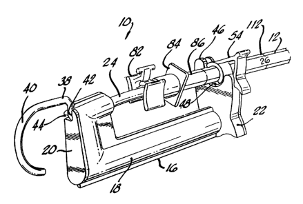
FIG. 1 is a partial perspective view of an
intubation device embodying the novel features of the
present invention, showing the device ready for use with
an endotracheal tube;
FIG. 2 is a right side elevational view of the
a
intubation device, shown with the endotracheal tube
removed;
FIG. 3 is a left side elevational view of the
intubation device, similar to FIG. 2;
FIGS. 4A-48 are cross-sectional views of a tube
clamp of the intubation device, taken substantially along
line 4-4 of FIG. 2,.showing the clamp in open and closed
positions, respectively;
FIG. 5 is a cross-sectional view of a tube stop
of the intubation device, taken substantially along line
5-5 of FIG. 2, showing the tube atop in an unsecured
condition; . ...
:. :~ .: :~ .. :.::: .. ,.,
... : FIG: ' 6 ~~ is another cross-sectional view of the
. . ubestop, si~ilar.~to::FIG:.5, showing the tube stop in a
secured condition;
. . _ . .. , ..: ...
FIG. : 7 is a :-perspective view of the ~ intubation
device, showing one preferred manner of holding the device
and tube for intubation purposes;
W0 92/19169 v ' ''~-: ~ PCTlU~92/03900 : ~.
21~p95~'~
FIG. 8 is an elevational view of the intubation
device, showing use of the device for orotracheal
intubation; and
5 FIG. 9 is an elevational view of the intubation
device, similar to FIG. 8, showing use of the device for
nasotracheal intubation.
As shown in the exemplary drawings, the present
invention is embodied in an intubation device, generally
referred to by the reference numeral 10, for use in
inserting an endotracheal tube 12 into a patient to
provide adequate ventilation and oxygenation of the
patient. The device 10 is advantageously designed for
j orotracheal or nasotracheal intubation, as well as for
subsequent confirmation of the placement and position of
in-place tubes. These and other features and advantages
.of:the invention are described in detail below.
FIG. 1 shows the device 10 connected to the tube
12 and ready for insertion into the patient s trachea 14
(FIGS: 8-9). The device 10 comprises a housing 16 having
a generally cylindrical body 18 with an extension 20 at
one end and a tube holder 22 at the other and. The
extension 20 connects one end of an elongated, tubular
r~sheath 24~ vto - he housing ~: l6 so that the ~'~eheath overlies
the ~-: tube-: holder : 22 ~ and 3s : ubstantially parallel :. to the
housings cylindrical body 18.v The sheath. 24 is
preferably made of a flexible plastic material to enable
'~ a~:.relatively.free bending~and manipulation of the sheath.
._... _..., , ..,., ,,..' ':.::: '_ .....~. ~_::. ". ~ .:..;~~ ~. '..~. ~
.~,~. _.;,...,.~ ,~ ;,.:~ , . .~ :~~.a~ . :.. ; ;.
FIGS. 2-3 . show elevational '.:. views of the
incubation device 10, with the endotracheal tube 12
omitted for purposes of clarity. It is noted here that
the sheath 24 is connected to the housing 16 so that the
F~'~',.:~. ~, .,~~,,. . . ,.;., ,,.; y. . ~..,... .,~..~.. ..,. .,
WO 92/19169' 'v ~~'v ~ PCT/US9Z/0390t1
21. 0 9 ~ 0'~
11
sheath extends upwardly at a slight angle relative to the
housings cylindrical body i8. This causes the sheath 24
to be slightly spaced from the tube holder 22. The
significance of this spacing of the sheath 24 is explained
in more detail below.
As shown best in FIG. 3, the free end 26 of the
r' sheath 24 which is not connected to the housing 16
includes a special light 28 that may be selectively
illuminated by operating a switch 30 on the housing. The
light 28 comprises a filament type bulb and may include a
reflector shield 32 on its backside to reflect a
substantial portion of the lights illumination to one
p1
'' side of the sheath 24. The bulb 28 also includes a lens
33 to focus a portion of the illumination in a direction
x
in which the free end 26 of the sheath 24 is pointing.
The bulb 28 is powered by batteries (not shown) in the
'
cylindrical body 18 of the housing 16, and the electrical
connection between the batteries and the bulb can be
accomplished using conventional conductors 35 (FIGS. 5-6)
~f~ within the sheath 24:
The directional nature of the light bulb 28
advantageously directs a substantial portion of the.
illumination from the bulb to one side of the sheath 24.
Nevertheless, it. is still desirable to have an. adequate
L,_ .. .:.. , asount~: ~of- illumination directed toward the .airway: The
~: lens::7'33~satisfies : thiswillumination vnesd ~~~by=-focusing a
portiow=~.of-the bulbs illumination in~thie-direction.
:: .The switch 30 for controlling illumination of
the ~~bulb~ : is shown in FIG. 3 : ~ Thev ~ switch ' 30 comprises a
slide switch 34 for manual movement by ones finger to an
"on"- or °an '"off" position to respectively connect and
disconnect electrical power to the bulb 28. In the ion"
position, the bulb 28 is illuminated continuously, and in
the "off" position the bulb is not illuminated. The slide
WO 92/19169 ~. ~.:;" PGT/US92/03900 .~~~~
210 9;5"~L'7 . i, v
12
switch 3A also may optionally include a button switch 36
that may be depressed to provide pulses of illumination,
with the slide switch 34 in either the "on" or "off"
poRition.
It will be appreciated that the bulb 28 can
generate relatively high temperatures when it is
illuminated for an extended period of time. Pulsing of
the bulb 28 should help to significantly reduce heat
build-up and high temperatures. The heat that is produced
by the bulb 28 should not pose a problem in any event, in
view of the heat exchanging nature of the upper airway,
and because use of the intubation device 10 of the present
invention, as described below, does not involve contact
between the bulb 28~and the patient s tissue.
With further reference to FIGS: 1-3, the
intubation device 10 further includes a trocar or stylet
'' 38 in the form of a thin wire that is received within a
hollow shaft in the sheath 24. The trocar wire 38
preferably is aade of a ductile or aalleable material that
is capable of being bent and maintained at varying angles .
When inserted in the sheath 24, the trocar wire 38
r.. ...
provides added stiffness to the sheath to facilitate
orotracheal intubations. It also allows the free end 26
of the sheath 24 to be bent at an angle to further
facilitate . intubation: ,:: < When the . . trocar wire 38 is
removed, the sheath. 24: :as. very pliable- and easily. conforms
f ;j~~-:~ to.:: the :.vanatomy ~of .vthe->;--upper ~ airway. genes; . the :.
trocar
;wire :.38 ais. not rused in::nasotracheal intubations:
J:::_:.::During intubation using the trocar wire 38, the
_ ~ ~ sheaths s v: free end::: 26 is usually bent in the ~ shape of a ,
...hockey stick, as shown:in FIG. 7. To maintain this shape,
-the:vtrocar wide 38 should:not rotate inside the sheath 24. .
To preventrsuch-rotation~-the trocar wire 38 is provided
with a curved handle 40 that is received within one of two
notches 42 and 44 formed in the extension 20 of the
WO 92/19169' PGT/US92/03900 ,~r
pg~0'~ ~ 13
21
housing 16. Thus, when the trocar wire 38 is fully
inserted into the sheath 24, the handle 40 will fit within
one of the notches 42 and 44 (FIG. 1).
The trocar wire 38 typically is withdrawn from
the sheath 24 midway during an orotracheal intubation. In
this regard, it is important that the wire 38 be withdrawn
smoothly and as easily as possible to prevent tissue
trauma. Accordingly, the hollow shaft of the sheath 24
preferably is lined with a material having a low
coefficient of friction. In the preferred embodiment,
this material comprises teflon, which may be used to
construct the entire sheath 24 and not just the lining of
the sheath s hollow shaft. The trocar wire 38 also may be
coated with a material having a low coefficient of
friction, such as teflon, to further facilitate insertion
and withdrawal of the wire.
a The intubation device 10 also includes a tube
clamp 46.for clamping the endotracheal tube 12 to the
housing l6 after the sheath 24 has beenevinserted into the
tube. Thus, the tube clamp 46 prevents relative movement
between the tube 12 and the sheath 24, which is very
important to the success of the intubation process. As
shown best in FIGS. 4A-48, the tube clamp 46 is connected
. . : to the : . foi-ward end of the housing 16 and comprises the
.tube..holder.w22,~.which has:a curved portion 48 facing the
overlying sndotracheal tube l2 (FIG. 1). A flexible band
4;s :: 50 : overlies : : ahe : ~~ potion 4 8 and has one end 51
30r secured to one side of the curved portion and another end
. -.53 that: . rests against the opposite side of the curved
<-: :portion where :. , it extends ~ upwardly beyond the curved
... =portion: The band 50- also is configured so that an
~intsr~ediate section 52 of the band 50 is spaced from the
-curved portion 48. This-arrangement allows the band 50 to
have the properties of a spring, in that depressing the
end 53 will move the intermediate section 52 toward the
','.v. .:..~ ..wc,. .,.:... ,-;:.. ,.. , '.:.; .., .:' .;.... .,~, y;., _.. ..
;.~.... ~..' '.:..:..,. 3..,... , .... . . .,..
.. . . ~ . . . . ' .... ..i . . .. . t: ; , .. . . . . , . . . , : .: ,
WO 92/19169. ''~'r '_:>t~ ~ ~ PGT/US92/03900
21095 0'7
14
curved portion 48 of the tube holder 22, while releasing
it will cause the intermediate section to spring back to
its original state, as shown in FIG. 4A.
The tube clamp 46 further comprises a clasp 54
having one end pivotally connected to the tube holder s
curved portion 48 on the same side as the band end 53.
This pivotal connection allows the clasp 54 to pivot
between a clamped and unclamped position with respect to
the tube holder 22. In the unclamped position, shown in
~_ ~ FIG. 4A, the clasp 54 is received within a recess 56 of
the tube holder 22. Here, the clasp 54 is completely out
of the user s way and there is no risk of it catching on
,;
anything. To ensure that the clasp 54 remains secured in
the unclamped position, a bead 58 on the clasp 54 is
adapted to snap-fit within a groove 60 in the recess 56.
In the clamped position, shown in FIG. 48, the clasp 54
has a finger 62 which is received in a snap-fit engagement
with a notch 64 on the other side of the tube. holder s
curved portion 48, opposite the side where the clasp 54 is
pivotally.connected to the -tube holder 22. Here, the
clasp 54 is completely closed and locked in place, such
that a curved section 66 on the clasp 54 overlies the
curved portion 48 of the tube holder 22 to form a
~. 25 substantially cylindrical clamp. Closing,of the clasp 54
also contacts the band end 53 causing it to conform to the
~,~.; ~ . ,curvature : of -the clasp!a ;curved., section 66 (FIG. ~ 48) .
.n. ~ f : ....~:_... . ~ . ,. a . ~ ~ .. .. a. .... .p .. ... ~. :' . .. . . .
...
d
l .F;e_ ;, :A tab 68 alsoais provides on the tube clamp 46,
. having a concave configuration 70 on one side and a convex
.,;configuration, ?2 on- the other.. The tabs concave
..configuration.:, 70 facilitates:,. unsnapping of the :clasp 54
when it is in the closed position and pushing the bead S8
into the groove 60, thereby securing the clasp 54 in the
:.35-:unclamped -position. The tab's convex configuration 72
facilitates moving the bead 58 out of the groove 60 and
WO 92/19169' : ' ''~ :°;. ~ ~ ~ . PCT/US92/U3900
15 .~.>",'
210950'
snapping the finger 62 into the notch 64, thereby securing
the clasp 54 in the clamped position.
The tube clamp 46 described above has many
advantages. One very significant advantage is that when
the clasp's finger 62 is released from the notch 64, the
end 53 of the band 50 will urge against the clasp's curved
section 66 and cause the clasp 54 to rapidly pivot away
a,
from the tube 12. As.noted previously, the sheath 24 is
connected to the housing 16 at a slight upward angle
relative to the housing's cylindrical body 18. Thus, the
Yd
.,
angular orientation of the sheath 24 with respect to the
housing 16 also tends to eject the tube 12 away from the
,:
tube holder 22 and to maintain the tube in a spaced
relation from it when the clasp 54 is released. The
combination of these features advantageously allows free
and unrestricted access to the endotracheal tube 12,
without interference by the tube holder 22, clasp 54 or
other structure of the intubation device l0 to facilitate
the rapid .and easy removal of the. device from the
endotracheal tube. . . . . ~~ ..
l~nother important advantage of the tube clamp 46
is its ability to receive and clamp various size
endotracheal tubes. The clamp 46 presently is adapted to
.. receive size 7, 8 and 9 tubes.. When clamping large size
:::~... :, tubes,~..auch as size 9,:: the .clasp 54 is firmly .moved to the
.= ,' w: :closed. ~~position and :. he f lexible °-band ~ 50: ,is~
vforced down
.,.~,,~~y.;~tightly wagainst. the :curved-:portion 48:.:of::. the tube
- Bolder 22..~ ~ When clamping small size tubes, vsuch as size
.. . .,:.-7, -,it:will . be easier to. snap the clasp 54 to the closed
.. ~ ~ -:r~:positfon.:.. and the flexible band 50 will bend, ~ but it
normally will.not be forced all the way against the curved
portion 48 of the tube holder 22.
~ .w.. ,
To help prevent slippage between the tube clamp
46 and the endotracheal tube 12, the flexible band 50 is
W0:92/19169 ; ., ; ~. , « ~ PCT/US92/03900 ~ .' ~ .
16 ~,.~;~~~~~.
provided with a friction enhanced .surface. In the
preferred embodiment, for example, the band 50 is made of
metal and the friction enhanced surface comprises a
plurality of protrusions 74 on the band that are designed
to bite into the outer surface of the tube 12 when the
clasp 54 is in the clamped position. It will be
appreciated that other types of friction enhanced surfaces
may be used to inhibit slippage between the clamp 46 and
tube 12.
It is also noted that the clasp 54 can be
'' conveniently and quickly moved to the closed position for
any size tube with one simple movement that secures the
ra
finger 62 on the clasp 54,within the notch 64 on the tube
holder 22. This has advantages over multiple notch
devices, where a different notch corresponds to a
different sized tube. It can be seen that use of a
multiple notch device would be more time consuming and
leave an undesirable margin for error, should .the wrong
. 20 :notch be:selacted.. The present invention avoids these
problems and eliminates any guesswork-by the user:
When preparing to use the intubation device 10
of this invention, the free and 26 of the sheath 24 will
25::~.'be inserted into the distal end~76 'of the endotracheal
~;,. ; ube 12 .until the- light. bulb 28.~ ie aligned with a side
~~.; ~ ;:..:hole ~::: in the :tube; nor : :. if:< : the. tube is beveled, - at
the
~.,~..w-, ;'proxiaal edge~~~78 .of.vthe:-bevels 80::.- (FIGS:=-<~e-9) :
~:=.art this
. ._. <:location;- the : .light:x'28 ,:.;is at : the: end :v-of he j_
endotracheal
~:30 .:tube 12 and serves tosubsequently identify its. location
~:=:..~ an vthe patient~s:..trachea 14.t:=:°The :clasp .54 is then
secured
-v.-in . they. clamped . position ~:v.to:..prevent relative ~ movement ,
.-between the sheath 24 and the tube 12:.. .
35 Figs. 5-6 show a tube stop 82 on the sheath 24
to identify when the light bulb 28 is aligned with the
tube s distal end 76. The tube stop 82 may be
~5~
WO 92/19169 ' ' ~ .~PGT/US92/03900 . :'
~p g.5 0'~ ~~ -~'
2
conveniently moved relative to the sheath 24 until it
abuts a fitting 84 at the proximal end 86 of the~tube 12,
where it is thereafter locked in place. Once locked in
place, the tube stop 82 allows the light bulb 28 to
consistently and reliably be positioned at the distal end
76 of the tube 12. The tube stop 82 is locked and
unlocked by interaction of the tube stop s body 88 and
various components, such as flaps 90 and 92, flanges 96
and 98, tabs 100, 102 and 104, a protrusion 105, flange
ends 106 and 108, and a lip 110.
Because of the importance of having the light
bulb 28 properly positioned at the tube s distal end ?6,
a second means of ensuring,proper positioning is provided.
It comprises reference numerals 112 on the sheath 24 at
locations that are 26 and 29 centimeters, respectively,
from the free end 26 of the sheath. It is known that
virtually all endotracheal tubes have reference markings
on their outer surface corresponding to the distance in
centimeters from the distal end of the tube.. Therefore,
by aligning . the .: reference numerals 112 on the sheath
24
with the centfaster aarkings on the endotracheal tube 12,
the location of the light bulb 28 with respect to the
distal end 76 of the tube 12 can be visually determined.
These reference numerals on the sheath 24, therefore,
provide a reliable visual backup to the tube stop 82.
This is important when the sheath 24 is inserted into an
-. ; in-place.tube:for:;the-purpose of accurately conffirming
and
detarmining:~ the. position ~ of the distal .end . 76 of
;' the
.
. .
endotracheal tube 12, which should be half-way between the
a
patients:vocal cords 114 and caring 116. . ..
~
~~
. . .
.
The use of the intubation device 10 of the
present invention in conjunction with an endotracheal tube
12, together with other features and advantages of the
invention, will now be described. Of course, all
intubation procedures must be preceded by adequate
WO92/19169 ' . ~ . PGT/US92/03900''~'d"
. 210907
18 - ..
suction, oxygenation and ventilation of the patient.
Following these routine procedures, the intubation device
may be used, with or without a laryngoscope (not
shown), to insert the endotracheal tube 12 into the '
5 patient s trachea 14. orotracheal intubation will be
described first in conjunction with FIG. 8, followed by
nasotracheal intubation in conjunction with FIG. 9.
With the trocar wire 38 in place, the sheath 24
10 is lubricated and inserted into the distal end 76 of the
I, .
endotracheal tube 12. When the light bulb 28 is aligned
with either the side-hole or proximal edge 78 of the bevel
4
80 at the distal end 76 of the endotracheal tube 12, the
clasp 54 is pivoted from the unclamped position and moved
to the clamped position to prevent relative movement
between the sheath 24 and the tube 12. If it is
anticipated that the intubation device l0 may be needed to
check placement of the endotracheal tube 12 at a later
,,
time, the tube stop 82 is elideably moved along the sheath
~24_until it contacts the fitting 84 at the proximal end 86
_~of ..tee endotracheal.. tube:::,,~12where it is thereafter
r_snapped'to the locked position: The sheath 24 and tube 12
are then bent at a right angle into the shape of a hockey
stick, as shown in FIG. 7, and the slide switch 34 is
'ovad to the ion", position to illuminate the light bulb
.~ ;28. .. a':. . .~ .... .
,, ~ ~.. :_.:.. .. . .. .,.. . . . .t:...,, ... ... . .... .. ~...... . . ....
. _ ...
~a ~= r ~.:~ : :. .. ..~: : ~-x ~ . vIf > : a °~:laryngoscope ~.: s :
used w to v expose the - upper
~_:-. =airway sanatoay., :~ he illuiination :<from the :light bulb 28
.30 will -aid in visualizing the ~ airway. even further. Under
ideal circumstances,~~..visualization of therpatient~s vocal
cords 114 will be possible. Thus, with the end of the
~endotracheal tube l2 lightly lubricated and the light bulb
. ~ 28 tested, the user may stand to either the right or left .
-aids of the patient,-holding the intubation device 10 in
the dominant hand. The distal end 76 of the tube ~12 may
be inserted into the patient ~ s mouth 118 and up against
.,~ ..v" . :'~.
WO 92/19169 ~ . PCT/US92/03900'~'
2209507
19
the cheek, with the light bulb 28 illuminated to provide
a reference degree of illumination visible through the
patient's cheek. The patient's tongue 120 and jaw 122 are
then lifted forward and upward, slightly opening the
patient's mouth 118. This causes the epiglottis 124.to be
lifted up and out of the way of the advancing tube 12.
Although the light bulb 28 can be illuminated continuously
during this process, if the ambient lighting is extremely
bright, it may be helpful to pulse the light bulb 28 with
the button switch 36 to improve the perception of the
illumination through the patient's skin. Next, the distal
end 76 of the endotracheal tube 12 is slid along the
tongue 120 until the distal end ?6 of the tube 12 "hooks
up" the epiglottis 124., As the tip of the tube 12
approaches the glottic opening 126, the transilluminated
glow from the light bulb 28 should be seen and should be
relatively distinct when the tube tip 76 enters the
larynx. The transilluminated glow through the larynx
should be bright and circumcised and substantially the
seas as the reference degree of illumination previously
seen through the patient's cheek.
The absence of a distinct transilluminated glow
in the larynx indicates that the tube tip 76 is in the
esophagus 128 and not the trachea 14. In these
- circumstances,: theetube 12 should be withdrawn slightly
_ . and':-the ..attempt': to venter the larynx should --be ~ repeated.
~. In this regard,'"some users ~-prefer ' to "place the tube tip 76
,~.:. ~:.first~in~~one-rof ;:the'.~;pyrifora fossaesince~:this area is
readily=transilluminated and provides a'further reference
., . pointfrom ~:: which='~=:.to medially direct ~ the ~~tube tip 76
._ .. .. = ~: : ~.ough v the ~glottic'~ opening 126 . _ . . . . ...:
--. . ..' . .:~ ", ._. W i .. . .. .. . . .. . ~. .
... v.-. In -any event; once a proper transilluminated
glow is detected-.in the.larynx, the endotracheal tube 12
is advanced slightly and the trocar wire 38 is gradually
retracted about 3-4 inches. With the trocar wire 38
WO 92/19169 , ~':;~ ' ~ PCT/L1S92/03900 ;r
2 0 ~ ~ e)
retracted, the free end 26 of the ~ sheath 24 and
endotracheal tube 12 become pliable and easily conform to
the upper airway, anatomy. This allows further advancement
of the tube 12 into the trachea 14 while minimizing the '
risk of tracheal wall damage or other trauma. ._.
As the tube 12 and sheath 24 continue to be
advanced into the trachea 14, illumination from the light
bulb 28 will be visualized through the patient s skin. If
desired, the bulb 28 may be pulsed by depressing the
button switch 36. The tube 12 will be advanced until
illumination of the bulb 28 is visualized in the area of
the eternal notch 130, indicating that the distal end 76
of the endotracheal tube ,12 is at the desired location
half-way between the patient s vocal cords 114 and caring
116. It is noted that the transilluminated glow at the
eternal notch 130 should be substantiall~~ the same as the
reference degree of illumination visualized through the
patients cheek at the start of the intubation: process.
.The-.cube l2 should be held firmly.while the clasp.54 is
released, and the sheath 24;thereafter withdrawn from the
tube i2. The patient can then be ventilated, the chest
auscultatad, and the tube 12 anchored in place in the
conventional aanner.
:- i ~ = When using : the intubation device to of the
r-~ ~;t~.:present :invention rfor nasotracheal: intubation, the :trocar
fn, . r~~e : 38 ; is -removed ~ and~~.not: Bused. -.,:a Removal of the arocar
r; ~_~vire ., 38:; ., allows . thea~ sheath ., 24 e-to , become. .: pliable
and
. . 30 flexible, similar to a stylet, for.~easy insertion into the
,~.;.:nasotracheal tuba... Thus,ahe light,:bulb 28 at the end of
the sheath 24 not ~ . only ;~:,< provides - ~ he - necessary
transillueinating light, but the flexible yet firm sheath
24 gives support to the tube 12. This helps direct the
35 tube; tip a6 anteriorally, particularly when using a
directional-tip tube.
WO 92/19169' 2 2 ~ ~ ~~ 0'"~ PGT/US92/a3900
~""':.
21
The procedure for nasotracheal intubation using
the intubation device 10 of the present invention is not
very different from the previously described technique for
orotracheal intubation. All of the procedures described
above are followed to a point just prior to insertion of
the tube tip 76 along the tongue 120 and into the
epiglottis 124. Thus, the patient is adequately prepared,
the tube 12 is clamped to the intubation device 10 and
lubricated, and a reference degree of illumination may be
visualized through the cheek.
Next, the tube 12 is positioned and slid along
the nasal floor or septum 132 to curve around the
posterior pharyngeal wall. If a directional-tip tube is
used, tension on a string loop (not shown) helps to curve
the dietal'end 76 of the tube 12 around the pharyngeal
wall. The light bulb 28 at the sheath s free end 26 can
then be illuminated, by either moving the slide switch 34
to the ion" position or by depressing the button switch
36, and the patient s tongue 120 and jaw 122 pulled
forward and upward. This movement essentially lifts the
epiglottis 124 up and out of the way, similar to the
orotracheal technique. Once the tube tip 76 has entered
the glottic opening 126 and is in the larynx, the
procedures of transillunination and insertion are
essentially the same as those described above in
connection with orotracheal intubation.
Once the endotracheal tube l2 has been properly
placed in the trachea i4, it may be desirable at a later
a time to recheck its placement. If the endotxacheal tube
- vl2 has somehow been moved out of the'trachea l4 and into
the esophagus 128, or has passed the caring 116 and
extended into one of the airways to one of the lungs,
serious complications and even death could occur.
Therefore, confirmation of tube placement is essential to
proper ~~atient care.
.
WO 92/19169 ' '. '' ° , , , ;. ~ ~ , :: ~y ~ PCT/US92/03900
22 . '~'1U9~0'~
To check placement of the endotracheal tube 12
using the intubation device 10 of the present invention,
the patient is first suctioned appropriately and
hyperventilated with oxygen. With the trocar wire 38 '
a 5 removed, the flexible sheath 24 is lubricated and placed
,,
inside the patient's mouth 118 and up against the cheek to
' check light intensity and establish a reference degree of
>,;f illumination. The sheath 24 is then inserted into the
tube 12, preferably with the slide switch 34 moved to the
"on" position and the light bulb 28 illuminated. As the
sheath 24 is inserted into the tube 12, a bright glow of
~~illumination should be first seen in the oropharynx. As
the sheath 24 is continually advanced, the illumination
will diminish as the bulb, 28 passes the patient's vocal
cords 114, and it will then reappear at the laryngeal
prominence.' If the tube stop 82 has been previously set,
.3s described above, the sheath 24 will be inserted until
the tube stop 82 abuts the fitting 84 at the proximal end
A
p, 86 of the tube 12. At this point, the glow should be
visible at the eternal notch 130, thereby confirming
proper placement of the tube 12 half-way between the
patiant~s vocal cords 114 and carina 116. If the glow
does not appear, or if the illumination is not in the
proper location, then the tube 12 should be adjusted
appropriately. ~ The sheath 24 can then be removed and
ventilation continued.
. ;. : .. ....... ~. . ~: . .:
. While a particular form of the invention has
-been-,311ustrated and described, it-.will'be apparent that
various modifications can be made without departing from
the: pirit and scope of the inventions Therefore, it is
not intended that the invention be_limited; except as by
the appended claims.: ,