Note: Descriptions are shown in the official language in which they were submitted.
~O 93/00025 2 1 0 9 6 2 0 PCT/l~S92/0~769
_ 1
METHOD fOR MANUFACTURING A REFASTENABLE MECHANICAL
FASTEN~NG SYSTEM HAVING AZIMUTHALLY ANGLED PRONGS
AND FAS~ENING SYST~M PRQDUCED THREFROM
FIELD OF tHE INVENTION
The present 1nvent10n relates to refastenable mechan1cal
fasten1ng systems hav1ng az1muthally angled free fon~ed prongs
and the process of manufactur1ng such fasten1ng systems.
BACKGROUND OF THE INVENTION
Refastenable mechantc~l fasten1ng systems are well known 1n
the art. Typ1cally such fasten1ng systems 1nvolve two ma~or
components a prong wh1ch 1s ~o1ned to a substrate and engages
w1th a complementar~ second component the rece1v1ng surface. A
pro~ect10n of the prong of the fasten1ng system penetrates the
rece1v1ng surface and e1ther engages or 1ntercepts strands or
f1bers of the rece1v1ng surface. The result1ng mechan1cal
interference and phys1c-1 obstruct10n prevent removal of the
fasten1ng system from the rece1v1ng surface unt11 the separat10n
forces exceed e1ther the peel or shear strength of the fasten1ng
system.
Presently refastenable mechan1cal fasten1ng systems are made
by at least two general methods. One method requ1res a plural1ty
of f11aments each of wh1ch may be fonmed 1nto two prongs.
Examples of fastentng systems produced by th1s method are shown 1n
wo 93/0002~ 2 210 9 6 2 0 Pcr/~s92/o176s
U.S. Patent Ho. 2,~17,~3~, 1ssued September 13, 1955 to de
Mesteral and U.S. Patent No. 3,943,981, 1ssued March 16 1976 to
De Brabandar wh1ch teach ra1sed p11e of loops. Related
teach1ngs are shown 1n U.S. Patent No. ~,216,25?, 1ssued August S
1980 to Schams et al. U.S. Patent No. ~ 54,183, lssued June 12,
198~. to ~ollman nd U.S. Patent No. 4,~.63,~86, 1ssued August 7
198~, to Matsuda. These refc~ enc~s te~ch heat1ng the ends of
polymer1c monof11aments. Other rel~ted teach1ngs of fasten1ng
systems p~Gductd b~ the f1rst ~ethod are dlsclosed 1n U.S. Patent
No. ~"307,~93, 1ssued December 29, 1981 to Och1~1 and U.S. Patent
No. 4 330 90~ 1ssued May 25, 1982 to Och1a1.
The second general ~ethod con~nonly uttl1zed to manufacture
mechan1cal fasten1ng syste~s 1s to mold or extrude the systems as
111ustrated 1n U.S. Patent No. 3,1~.~,528, 1ssued September 8 196~,
to Erb and U.S. Patent No. 3,59~"863, 1ssued July 2~, 1971 to Erb.
Cont1nuous 1n~ect10n Inoldlng 1s taught 1n U.S. Patent No.
3,59~.,865, 1ssued July 27, 19~1 to Erb.
Var10us prong structures are 111ustrated 1n the pr10r art.
For example the references d1scussed above teach fasten1ng
systems hav1ng stems of generally constant cross sect10n. U.S.
Patent No. 3,708,833, tssued January 9 1973 to R1b1ch et al.
d1scloses a prong wh1ch 1s some~hat tapered from the prox1mal end
to the d1stal end and perpend1cularly pro~ects from the substrate.
European Patent Appl1cat10n No. 0,276,9~0, publ1shed January
26, 1988, by the Procter ~ 6a~ble Company 1n the name of Scr1pps
d1scloses a fasten1ng dev1ce hav1ng a constant cross sect10n stem
or1ented at an ngle between about 30- ~nd bout 90- relat1ve to
the base.
Fasten1ng systems hav1ng free fo~ned prongs generally are
produced w1th all the prongs or1ented 1n one d1rect10n 1.e. the
mach1ne d1rect10n of the substrate. There 1s however a need for
fasten1ng systems hav1ng free formed prongs where1n the prongs are
or1ented 1n a d1rect10n other than the mach1ne d1rect10n. For
example when a fasten1ng system hav1ng free formed prongs 1s used
as the fasten1ng means of a d1sposable d1aper a fasten1ng system
w1th prongs or1ented 1n th- cross-mach1ne d1rect10n of the
substrate can more eas11y be ppl1ed to the d1aper on a h19h speed
-
2 ~ 09620
diaper m~mlf~cturing line than can a fastening system with prongs oriented
in the machine direction of the substrate. There is also a need for fastening
systems having free formed prongs wherein the prongs are oriented in
several directions. For example, a fastening system having prongs oriented
5 in several directions will have a more isotropic peel strength than a fastening
system having all the prongs oriented in one direction.
These needs have been addressed in U.S. Patent Application
07/632,283 filed December 21, 1990 in the name of Dennis A. Thomas,
David J. K. Goulait, and Robert G. Cox, Jr. entitled "Refastenable
10 Mechanical Fastening System and Process of Manufacture Therefor", which
disclosed a method of manufacturing a fastening system having free formed
prongs which are externally biased, or forced, to orient in a direction other
than the machine direction of the substrate. However, this method tends to
orient substantially all, or a large number, of prongs in the same direction,
15 or orient the prongs in several different directions by uncontrolled
"scattering" of the prongs.
It is, therefore, an object of an aspect of the present invention to
disclose a method of producing azimuthally angled prongs.
It is an object of an aspect of the present invention to disclose a
20 method for producing a fastening system having prongs by which the general
direction of orientation of each individual prong can substantially be
controlled or manipulated.
It is an object of an aspect of the present invention to disclose a
method for producing a fastening system having prongs in which each prong
25 of the fastening system is oriented in a predetermined direction.
It is an object of an aspect of the present invention to disclose a
fastening system having prongs in which each prong of the fastening system
is oriented in a predetermined direction.
B
21 09620
3a
BRIEF SUMMARY OF THE INVENTION
Various aspects of this invention are as follows:
A method for manufacturing a fastening material having azimuthally
angled prongs, the method comprising the steps of:
providing a depositing member having cells, at least one of said cells
having a major axis and a minor axis, said minor axis being oriented in a
direction other than the machine direction of said depositing member;
providing a thermally sensitive material associated with said
depositing member;
heating said thermally sensitive material to at least the melting point;
providing a substrate transported in a first direction;
depositing discrete amounts of said thermally sensitive material from
said cells onto said transported substrate;
stretching said discrete amounts of thermally sensitive material in a
direction having a vector component parallel to the lane of said substrate;
and
severing said stretched thermally sensitive material to form prongs
having shanks, each of said shanks being azimuthally angled and having a
distal end and eng~ging means thereon.
A method for m~mlf:~cturing a fastening material having ~imllth~lly
angled prongs, the method comprising the steps of:
providing a depositing member having cells, at least one of said cells
having a major axis and a minor axis and having a dominant area on one
side of the machine direction centerline;
providing a thermally sensitive material associated with said
depositing member;
heating said thermally sensitive material to at least the melting point;
providing a substrate transported in a first direction;
B
2 1 09620
3b
depositing discrete amounts of said thermally sensitive material from
said cells onto said transported substrate;
stretching said discrete amounts of thermally sensitive material in a
direction having a vector component parallel to the plane of said substrate; and
severing said stretched thermally sensitive material to form prongs
having shanks, each of said shanks being azimuthally angled and having a
distal end and engaging means thereon.
A method for manufacturing a fastening material having azimuthally0 angled prongs, the method comprising the steps of:
providing a depositing member having cells, at least one of said cells
having a bottom surface comprising a f1rst portion and a second portion, the
depth of said first portion being greater than the depth of said second
portion;
providing a thermally sensitive material associated with said
depositing member;
heating said thermally sensitive material to at least the melting point;
providing a substrate transported in a first direction;
depositing discrete amounts of said thermally sensitive material from0 said cells onto said transported substrate;
stretching said discrete amounts of thermally sensitive material in a
direction having a vector component parallel to the plane of said substrate;
and
severing said stretched thermally sensitive material to form prongs
25 having shanks, each of said shanks being azimuthally angled and having a
distal end and eng~ging means thereon.
A fastening material for attaching to a complementary receiving
surface, the fastening material being manufactured according to any of the
fore~oin~ methods.
2 1 0 9 6 2 0
3c
An absorbent article comprising:
an outer cover comprising;
a topsheet;
a backsheet joined with said topsheet;
an absorbent core positioned between said topsheet and said
backsheet; and
a fastening material of the type set out hereinabove joined to said
outer cover.
By way of added explanation, the present invention relates to a
fastening system for attaching to a complementary receiving surface and the
fastening system produced therefrom. The fastening system has a substrate
and at least one free formed prong comprising a base, shank and eng~gin~;
means. The base of the prong is joined to the substrate
B
~0 93/0002' PCl /I~S92/04769
2109620
and the shank ls contlguous wlth and proJects outwardly from the
base. The engaglng means ls ~olned to the shank and pro~ects
laterally beyond the perlphery of the shank. The shan~ 1s
nonperpendlcularly orlented relatlve to the plane of the
substrate. ~he shank has lead1ng edge and tra111ng edge
def1n1ng ~ leadlng angle and trall1ng angle respect1vel~. ~he
lead1ng angle and tra111n9 angle are substant1~ d1fferent fro~
each other so that the s1des of the shank are nonparallel. ~he
shank also has n az1muth~1 anglo. The az1muth~1 angle can be
between about l and about 180- preferably between ~bout 20- to
about 160- relatlve to the MD.
The fastenlng syste~ may be made accordlng to the process
compris1ng the steps of heatlng a thermally sens1tlve mater1al
suff1c1ently to reduce 1ts v1scos1ty for process1ng and
preferably to at least 1ts melt1ng po1nt. A depos1t1ng member for
depos1t1ng dlscrete amounts of the heated mater1al such as
hot-melt adhes1ve thermoplast1c 1s prov1ded. The substrate to
wh1ch the ~ater1~1 1s to be ~o1ned 1s transported 1n a f1rst
d1rect10n relat1ve to the depos1t1ng member. The mater1al 1s
depos1ted on the transported substrate 1n d1screte amounts. ~he
d1screte amounts of mater1~1 are then stretched 1n a d1rect10n
hav1ng a vector component generally parallel to the plane of the
substrate. The stretched mater1al 1s severed to form ~ d1stal end
and engag1ng means ~nd the d1stal end nd engag1ng means w111
2S form an az1muthal angle between about l- to bout 180- preferablybetween about 20- to about 160- 1s 1mparted to the shank.
An 111ustrat1ve and su1table but nonl1m1t1ng use for the
fasten1ng system produced by the process of the present 1nvent10n
1s 1n con~unct10n w1th a dlsposable absorbent artlcle such s a
d1aper. Th1s example of one usage of the fasten~ng system of the
present 1nvent10n ls more fully descr1bed below.
BRIEF DESCRIPTIOH OF ~HE DRA~INGS
~hlle the Spec1f1cat10n concludes w1th cla1ms part1cularly
po1nt1ng out and d1st1nctly cla1m1ng the 1nvent10n 1t 1s bel1eved
the 1nvent10n w111 be better understood from the follow1ng
descr1pt10n taken 1n con~unct10n w1th the assoc1ated draw1ngs 1n
wh1ch 11ke elements are descr1bed by the same reference numeral
PcT/us92/0476s
~o 93/0002~ S
2109620
and related elements are des1gnated by addlng one or ~ore prlme
symbols or lncrementlng the numeral by lO0
Flgure 1 1s a photomlcrograph show1ng a perspect1ve v1ew of a
fastenlng system where1n the engaglng means are or1ented 1n
substant1ally the same d1rect10n;
Flgure 2 1s a s1de elevat10nal v1ew of one prong of the fasten1ng
system shown 1n ~1gure 1;
Flgure 3 1s a s1de elevat10n~1 v1ew of second embod1ment hav1ng
a generally sem1spher1c~11y shaped engaglng means;
F1gure ~ 1s a s1de elevat10nal schemat1c v1ew of one apparatus
wh1ch can be used to produce the fasten1ng system of the
present 1nvent10n;
F1gure 5 ts a photom1crograph show1ng ~ perspect1ve v1ew of a
fasten1ng syste~ where1n the engag1ng means are or1ented 1n
substant1ally random d1rect10ns;
F19ure 6 1s a perspect1ve v1ew of a d1sposable absorbent garment
ut111z1ng the fasten1ng system of the present lnvent10n
show1ng the topsheet and core part1ally cut-away;
Figure 7 1s a top plan v1ew of one prong hav1ng n az1muthal angle
of about 90 ;
Flgure 8 1s a front elevat10nal v1ew of one apparatus (onl~ a
port10n of wh1ch 1s shown) wh1ch can be used to produce the
fasten1ng syste~ of the present 1nvent10n hav1ng az1~uthally
angled prongs;
F1gure 9 1s a top pl-n v1e~ of a second apparatus wh1ch can be
used to produce the f-sten1ng system of the present 1nvent10n
hav1ng az1~uthally angled prongs.
F1gure lO 1s a top pl-n v1ew of on- cell hav1ng ma~or axes and
m1nor axes wh1ch can produce az1muthally angled prongs;
F19ure ll 1s a top plan v1ew of a cell havlng a ma~or ax1s and
m1nor ax1s wh1ch can produce az1muthally angled prongs;
F~gure 12 1s a top plan v1ew of another cell hav1ng a ma~or ax1s
and m1nor ax1s whlch can produce az1muthally angled prongs;
F1gure l3 1s a top plan v1ew of a cell hav1ng a ma~or ax1s and
m1nor ax1s;
F1gure l4a 1s a top pl-n v1ew of a closed-end cell hav1ng a
c1rcular sect10nal area at the surface of the pr1nt roll;
PC~r/~S92/04769
~O 93/00025 6
2109620
F1gure l4b ls a cross-sectlon-l vlew of the cell of Flgure l~a;
Flgure 15a ls a top plan vle~ of closed-end cell havlng two
bottom surface portlons of unequal depth;
Flgure 15b 1s ~ cross-sect10n-1 vlew of the cell of F1gure l5a;
F1gure l6 1s a photom1crograph showlng a top pl~n vlew of ~
fastenlng system of the present 1nvent10n where1n the prongs
were produced from cells slm11ar to the cell shown 1n F1gure
12 and engag1ng means arc or1ented 1n subst~nt1~11y the same
d1rect10n; and
Flgure 17 ls a photom1crograph show1ng a top pl~n v1ew of a
fasten1ng system of the present 1nventlon whereln the prongs
were produced from cells s!mllar to the cell shown ln F1gure
ll and engag1ng means are or1ented ln substantlally the same
dlrectlon.
DETAILED DESCRI~ION OF THE INVEH~ION
~he fasten1ng system 20 of the present 1nvent10n comprlses at
least one prong 22 hav1ng an azlmuthal angle ~nd preferably an
array of such prongs 22 Jolned to a substrate 2~ ln
predetermtned pattern as shown 1n F1gures 16 and 17. Though 1t
should be understood that because the gener~l orlentat10n of each
lndlvldual prong can substantlall~ be controlled the prongs 22 of
the arra~ need not be orlented ln the same d1rect10n and 0a~ be
or1ented 1n man~ d1fferent dlrect10ns. The arr~r ma~ cons1st of
azlmuthall~ angled prongs be1ng pos1t10ned dJacent to
non-az1muthall~ angled prongs or prongs hav1ng ~ dlfferent
az1muthal angle. It should therefore be understood that the
prongs 22 of the arra~ ma~ be arranged 1n an unl1m1ted number of
poss1ble patterns.
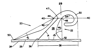
A prong 22 has a base 26 shank 28 and engaglng means 30.
The bases 26 of the prongs 22 contact and adhere to the substrate
24 and support the prox1mal ends of the shanks 28. ~he shanks 28
proJect outwardly from the substrate 2~ and bases 26. ~he shanks
28 term1nate at a d1stal end 29 wh1ch 1s Jo1ned to an engag1ng
means 30. ~he engag1ng means 30 pro~ect laterally from the shanks
3~ 28 1n one or more d1rect10ns and mar resemble ~ hook-shaped t1ne.
As used hereln the ten~ lateral means hav1ng ~ vector component
generall~ parallel to the plane of the substrate 2~ at the
pr1nclpal prong 22 under cons1der-tlon. ~he proJect10n of an
~0 93/00025 PC~r/~S92/04~69
2109620
engaglng means 30 from the shank 28 perlpher~ ln a lateral
directlon allows the engaglng means 30 to be secured to
complementary recelvlng surface (not shown). ~h~ engaglng means
30 1s Jolned to and preferabl~ contlguous w1th the d1stal end 29
of the shank 28.
The array of prongs 22 may be produced by any su1table method
whtch y1elds a free for~ed prong 22. As used here1n the ten~
free formed~ means a structure wh1ch 1s not removed from a mold
cav1ty or extrus10n d1e 1n solld form or w1th a def1ned shape.
~he prongs 22 are deposlted onto a substrate 24 1n a molten
preferably 11quld state and solldl~y by cool1ng unt11 rlgld and
preferably free~1ng ~nto the des1red structure and shape as
descrlbed herelnafter.
~he free formed arra~ of prongs 22 1s preferably produced by
a manufactur1ng process descrlbed herelnbelow wh kh 1s s1m11ar to
that process commonly known as gravure pr1nt1ng. The free formed
array of prongs 22 ~a~ also be produced by a manufactur1ng process
whlch ts slm11ar to that process commonly known as screen prlnt1ng
or mlcro-screen prlnt1ng ~hlch ls more preferred 1f a denser
array of prongs 22 ls deslred. A screen prlnt1ng process ls
descr1bed tn our commonly ass1gned co-pend1ng U.S. Patent
Appl-1cat10n; Procter and Gamble Case 4418; Denn1s A. ~homas and
Dav1d J.K. Goula1t; ~Screen Pr1nt1ng Method for Manufactur1ng A
Refastenable Mechan1cal Fastenlng S~ste~ And Fastenlng Syste~
Produced Therefrom- f11ed concurrentl~ herewtth; the
spec1f1cat10n and drawings of ~h1ch are 1ncorporated here1n by
reference. Other ~ethods of produc1ng free for~ed prongs 22 w111
be apparent to one skllled 1n the art. However for ease of
descr1pt10n only that process wh1ch 1s s1m11ar to the gravure
pr1nt1ng process wlll be lllustrated here1n.
Uslng the manufacturlng process whlch ls s1m11ar to that
process commonly known as gravure pr1nt1ng a substrate 2~ hav1ng
opposed faces 1s passed between the nlp 70 of two generally
cyl1ndrlcal rolls a prlnt roll 72 and a backlng roll 74 as
lllustrated at ~lgure ~. ~he rolls 72 and 74 have generally
parallel centerl1nes and are malntalned ln contactlng relatlonshlp
w1th the substrate 2~ as lt passes through the nlp tO. One of the
PCr/liS92/04769
.~ 0 93/00025
8 2109620
rolls referred to as the prlnt roll 72 has ~n array of bllnd
closed-end cavlt1es referred to as cells ~6 correspondlng to the
deslred pattern of prongs 22 to be deposlted on the substrate 2~.
~he second roll referred to as the backlng roll ~4 provldes the
react10n agalnst the prlnt roll 72 to pos1t10n the substrat~ 2~
aga1nst the prlnt roll ~2 as the substrate 2~ passes through the
nlp 70. Llqu1d thermall~ senslt1ve materlal preferably
thermoplast1c mater1al from wh1ch the prongs 22 are to be fon~ed
1s suppl1ed from a heated sourc- such as a trough 80. ~he
thermally sens1t1ve materlal 1s 1ntroduced 1nto the cells 76 as
the pr1nt roll 72 1s rotated about 1ts centerl1ne. ~he cells 76
conta1n1ng the thermall~ sens1t1ve mater1al transport 1t unt11
contact w1th the substrate 2~ 1s made and depos1t th1s mater1al
onto the substrate 2~ 1n the des1red pattern.
As relat1ve d1splacement between the substrate 2~ and rolls
72 and ~ 1ncreases the prongs 22 are stretched 1n a d1rect10n
hav1ng a lateral vector component generally parallel to the plane
of the substrate 2~ for~1ng the shan~ 28 and the engag1ng means
30. Flnall~ the moll of the prong 22 1s severed fro~ the
engag1ng means 30 by a severlng means 78. Due to the v1scoelastlc
propertles of the thermoplast1c the prong 22 contracts. lt 1s
also bel1eveJ that the prong 22 retracts under the 1nn uences of
grav1ty and shr1nkage wh1ch occur dur1ng cool1ng. The prong 22
then cools and preferably freezes 1nto a sol1d structure hav1ng
the engag1ng neans 30 cont1guous w1th the shank 28.
~he fasten1ng system 20 1s secured to a complementary
rece1v1ng surface. As used heretn the tenm rece1v1ng surface~
to wh1ch the engag1ng means 30 of the fasten1ng system ~0 are
secured refers to any plane or surface havlng an exposed face wlth
tlghtly spaced open~ngs complementary to the engag1ng means 30 and
def1ned by one or more strands or f1bers or alternat1vely ~h1ch
exposed face ls capable of local12ed elastlc deformat10n so that
the engag~ng means 30 may become entrapped and not w1thdrawn
w1thout 1nterference. ~he open1ngs or local1zed elast1c
deformat10ns allow for entry of the engag1ng means 30 1nto the
plane of the rece1v1ng surface wh11e the strands (or nondeformed
mater1al) of the rece1v1ng surface 1nterposed between the open1ngs
~0 93/0002~ PCr/l~S92/04769
2109620
(or deformed areasJ prevent ~lthdrawal or release of the f~sten1ng
system 20 unt11 deslred by the user or e1ther the peel or shear
strength of the fastenlng system 20 1s otherwlse exceeded The
plane of the rece1v1ng surface may be flat or curved
A recelv1ng surface hav1ng strands or f1bers 1s sa1d to be
~complementary- 1f the open1ngs between strands or f1bers are
slzed to allow at least one engag1ng me~ns 30 to penetrat~ 1nto
the plane of the rece1v1ng surface and the str~nds ~re s1zed to
be engaged or 1ntercepted by the engag1ng ~eans 30 A rece1v1ng
surface wh1ch 1s locall~ deformable 1s sa1d to be complementar~-
~f at least one engag1ng means 30 1s able to cause a local1zed
dlsturbance to the plane of the rece1v1ng surface wh1ch
d~sturbance res1sts removal or separat10n of the fastenlng system
20 from the rece1v1ng surface
Su1table rece1v1ng surfaces 1nclude ret1culated foams
knltted fabr1cs woven materlals non~:oven mater1als and
stltchbonded loop mater1als such as Velcro brand loop mater1als
sold by Velcro USA of Manchest-r New Hampsh1re A part1cularl~
su1table rece1v1ng surface 1s st1tchbonded fabr1c Number 970026
sold by the M1111ken Company of Spartanburg South Carol1n- If -
dense array of prongs 22 1s be1ng used another part1cularl~
su~table rece1v1ng surface 1s polypropylene non-~oven fabr1c
hav1ng a bas1s welght of about 1~.1 grams per square meter (O S
ounces per square yard) made by any su1table commerc1al card~ng or
spunbond1ng processes Su1table non-woven fabr1cs can be obta1ned
from Veratech Nonwoven 6roup of the Internat10nal Paper Company of
~alpole ~assachusetts 02081 As used here1n the ter
~dense arra~ of prongs refers to an arr~r of prongs haY1ng fro~
about 64 to about l600 prongs per square centlmeter (400 to 10 000
prongs per square 1nch) of substrate 2~
Referr1ng back to Flgure 2 to exam1ne the components of the
fastenlng system 20 1n more deta11 the substrate 2~ of the
fasten~ng system 20 should be strong enough to preclude tear1ng
and separat10n between tnd1v1dual prongs 22 of the fasten1ng
system 20 be a surface to whlch the prongs 22 w111 read11~ adhere
and be capable of be1ng Jo1ned to an art1cle to be secured as
deslred by a user As used here1n the tero ~o1n- refers to the
~0 93/0002~ 10 PCr/l~S92/0~1769
2109620
cond1tlon where a f1rst member or component 1s afflxet or
connected to a second member or component e1ther d1rectly; or
1nd1rectly where the f1rst member or component 1s aff1xed or
connected to an 1ntermed1ato ~ember or component wh1ch 1n turn 1s
afflxed or connected to the second member or component. ~he
assoc1atlon bet~een the f1rst member or component and the second
member or component 1s lntended to remaln for the llfe of the
art1cle. The ~substrate ls n~ exposed surface to wh1ch one or
more prongs 22 are ~olned.
~he substrate 24 should also be capable of be1ng rolled to
support convent10nal manufactur1ng processes flex1ble so that the
substrate 24 ma~ be bent or flexet 1n a des1red conflguratlon and
able to wlthstand the heat of the 11qu1d prongs 22 be1ng depos1ted
thereon w1thout melt1ng or 1ncurr1ng deleter1cus effects unt11
1~ such prongs 22 freeze. However 1f the substrate 24 1s a ~ater1al
wh1ch 1s sens1t1ve to heat then ch111ed roll may be used as -
back1ng roll 74 to enable such mater1als to be used as the
substrate. The substrate 2~ should also be aY~llable ln a var1ety
of w1dths. Su1table substr-tes 24 1nclude knltted fabr1c woven
mater1als nonwoven mater1als rubber v1nyl f11ms part1cularly
pol~olef1n1c f11ms and preferabl~ kraft paper. ~h1te kraft paper
havlng a bas1s we1ght of 0.08 k110grams per square meter (50
pounds per 3 000 square feet) has been found su1table. A
polyester f11m substrate 2~ hav1ng a bas1s ~e1ght of 17.1 grams
2S per squ-re ~eter (l4.26 gra~s per square yard) and ~ th1ckness ofabout 0.008 to about O.IS m1111meters (0.0003 to 0.006 1nches) has
also been found su1table.
~he base 26 1s the generall~ planar port10n of the prong 22
whlch 1s attached to the substrate 24 and 1s cont1guous w1th the
prox1mal end of the shank 28 of the prong. As used here1n the
ter~ base- refers to that port10n of the prong 22 wh1ch 1s 1n
d1rect contact ~1th the substratc 24 and supports the shank 28 of
the prong 22. It 1s not necessary that a demarcat10n be apparent
between the base 26 and the shank 28. It 1s only 1mportant that
the shank 28 not separate from the base 26 and that the base 26
not separate from the substrate 24 dur1ng use. ~he base 26 cross
sect10n should prov1de suff1c1ent structural 1ntegr1ty and hence
~0 93/00025 1 1 PCr/l :S92/04769
2109fi2~
area for the deslred peel and shear strengths of the fastenlng
system 20 based on the denslty of the pattern of prongs 22 and
length of the shanks 28 of the lndlvldual prongs 22 and further
provlde adequate adheslon to the substr-te 24. If a longer shank
28 ls utlllzed the base 26 should generally be of greater cross
sectlonal area to prov1de suff1clent adhes10n to the substrate 24
and adequate structural 1ntegr1ty.
~he shape of the footpr1nt of the base 26 on the substrate 24
generally corresponds to the shape of the cell's sect10nal area at
the surface of the pr1nt roll ~2. As used here1n the ter~
~footpr1nt- refers to the planar contact area of the base 26 on
the substrate 24. As the aspect rat10 of the s1des of the
footprlnt lncreases the prong 22 may become unstable when
sub~ected to forces such as gravltatlonal forces parallel to the
shorter dlmens10n of the footpr1nt. ~o produce a prong 22 wh1ch
1s not azlmuthally angled an aspect rat10 of less than about
1.5:1 ls preferred and a generally c1rcular footprlnt ls more
preferred. However to produce a~1muthally angled prongs 22
accord1ng to the method of the present 1nventton an aspect rat10
greater than about l.S:l 1s preferred and a generally elllpt1cal
or trlangular footpr1nt havlng an aspect rat10 greater than about
l.S:l 1s even more preferred. Methods of produc1ng a~1muthall~
angled prongs w111 be d1scussed 1n greater deta11 here1nbelow.
~he shank 28 1s cont1guous w1th the base 26 and proJects
outwardly fro~ the base 26 and substrate 24. As used here1n the
term 'shank' refers to that port10n of the prong 22 wh1ch 1s
lntermed1ate of and cont1guous w1th the base 26 and the engag1ng
means 30. The shank 28 prov1des tong1tud1n-1 spac1ng of the
engagtng means 30 from the substrate 24. As used here1n the ter~
~longltudlnal' means 1n a d1rect10n hav1ng a vector component away
from the substrate 24 wh1ch d1rect10n 1ncreases the perpend1cular
d1stance to the plane of the substrate 24 at the base 26 of the
prong 22 unless otherw1se spec1f1ed to be a d1rect10n hav1ng -
vector component towards such plane of the substrate 24.
Assoc1ated w1th the shank 28 and base 26 of each prong 22 1s
an or191n 36. ~he or1g1n~ of the shank 28 1s the po1nt whlch may
be thought of as the center of the base 26 and 1s typ1cally
~0 93/0002~ 12 PCI/I~S92tO4769
2109620
wlthln the footprlnt of the b-se 26. ~he orlg1n 36 lS found by
vlewlng the prong 22, from the s1de vlew. The ~slde vlew- ls any
dlrectlon radl~lly towards the shank 28 and base 26 whlch 1s also
parallel to the plane of the substrate 2~.
The lateral d1stance between the remote edges of the base 26
footprlnt for the part1cular slde vlew under cons1deratlon ls
found and th1s d1stance 1s b1sected y1eld1ng the m1dpo1nt of the
base 26 for such v1ew. ~hen b1sect1ng the footpr1nt of the base
26 for the part1cular s1de v1ew under cons1derat10n mlnor
I0 dlscontlnult1es (such as f~llets or asper1t1es 1nc1dent to the
attachment to substrate 2~) are lgnored. Thls polnt 1s the or1gln
36 of the shank 28.
The shank 28 makes an angle~~ w1th the plane of the substrate
24. As used here1n the term ~plane of the substrate~ refers to
the flat planar surface of the substrate 2~ at the base 26 of the
prlncipal prong 22 under cons1deratlon. ~he angle ~ 1s determ1ned
as follows. ~he prong 22 1s vlewed ln prof11e. The ~proflle
v1ew- of the prong 22 1S one of two part1cular slde v1ews and
found as follows. The prong 22 1s v1sually 1nspected froo the
slde vle~s such that the dlrectlon havlng the maxlmum lateral
pro~ectlon 38 becomes apparent. The lateral proJectlon~ ls the
dlstance taken laterall~ and parallel to the plane of the
substrate 2~ from the center of the base 26 1n such vtew 1.e. the
orlg1n 36 of the shank 28 to the pro~ect10n of the furthest
laterally remote po1nt on the prong 22 v1slble 1n such vle~l ~hen
such polnt 1s long1tud1nally and perpendlcularly pro~ected
downward to the plane of the substrate 2~.
It ~111 be apparent to one skllled ln the art that the
maxtmum lateral pro~ect10n 38 1s that pro~ect10n from the or1g1n
36 to the outer pertpher~ of the shank 28 or engag1ng means 30.
The slde v1ew of the prong 22 whlch maxtm1zes the lateral
pro~ectlon 38 ls the prof11e v1ew of such prong 22. It w111 also
be apparent to one sk111ed 1n the art that lf the fasten1ng system
20 ls produced by the process descrlbed and cla1med belo~ and 1f
the maxtmum lateral proJect10n 38 1s generally or1ented ln the
machtne dlrectton then the proflle vlew w111 be generally
ortented ln the cross-machtne dtrect10n. It wlll also be apparent
~0 93/00025 PCI /US92/04769
13 2109620
that lf the maxl~um lateral proJectlon 38 ls gener~ orlented 1n
the cross ~achlne dlrectlon then the prof11c v1ew wltl be
generally orlented ln the machlne dlrectlon The slde elev~tlonal
v1ew shown ln F1gure 2 1s one of the prof11e v1ews of the prong
22 lt w111 be further apparent to one sk111ed 1n the art that
there 1s another prof11e v1e~ generall~ l80- oppos1te fro~ the
prof11e vle~ shown (so that the max10u~ lateral pro~ect10n 38 1s
ortented towards the left of the v1ewer) E1ther of the two
prof11e v1ews 1s gener~ equ~ ell su1ted for the procedures
and usages descr1bed here1nbelow
~he or1g1n 36 of the shank 28 1s found as descr1bed above
w1th the prong 22 1n the prof11e v1ew ~h11e sttll ma1ntatntng
the prong 22 1n the prof11e v1ew an 1mag1nary cutttng plane
40-40 generall~ parallel to the plane of the substrate 24 1s
then brought 1nto tangency ~1th the per1phery of the prong 22 at
the polnt or segment of the prong 22 hav1ng the greatest
perpendlcular d1stance fro~ the plane of the substrate 24 Thts
corresponds to the port10n of the prong 22 hav1ng the h1ghest
elevat10n The 10aglnar~ cutt1ng plane 40-~0 1s then brought
one-fourth of such greatest perpend1cular dtstance closer to the
substrat- 24 from the po1nt of h1ghest elevat10n so that the
1mag1nar~ cutt1ng plane 40-~0 1ntercepts the prong 22 at
long1tud1nal elevat10n three-fourths of the pcfpend1cular d1stance
fro~ the pl~ne of the substrate 2~
~he 1~glnar~ cutt~ng plane 40-~0 ls then used to deteno1ne
three polnts on the prong 22 ~he f1rst po1nt 1s that po1nt ~here
the cuttlng plane 1ntercepts the leadtng edge 42 of the prong 22
and 1s referred to as the 7~X leadlng polnt ~ ~he leadlng
edge~ ls the apex of the per1phery of the shank 28 wh1ch
longltud~nall~ faces away from the plane of the substrate 24 ~he
second po1nt ls t1sposed about 180 through the center of the
prong 22 and 1s the po1nt where the cuttlng plane 40-40 1ntercepts
the tra111ng edge 46 of the prong 22 and 1s referred to as the 75X
tra11tng polnt 48 The ~tra111ng edge 1s the apex of the
per1pher~ of the shank 28 wh1ch longltud1nally faces towards the
substrate 24 and 1s generally oppos1tely d1sposed from the lead1ng
edge 42 ~he stra1ght ltne connectlng these two po1nts falls of
~VO 93/00025 ~ PCr/l~S92/04769
2109620
course w1th1n the cutt1ng plane 40-~0 nd ls b1sected to ~1eld
the m1dpotnt ~7 of the 1mag1nar~ cutt1ng plane ~0-~0 A stra1ght
11ne 1s then drawn connect1ng th- ~1dpo1nt ~ of the 1~ag1nar~
cuttlng plane ~0-~0 wtth the or1g1n 36 of th~ shank 28 ~t the base
26 The 1ncluded angle Q th1s 11ne def1nes relat1ve to the plane
of the substrate 2~ 1s the anglo ~ of the shank 28
Alternat1vel~ stated the ~ngle ~ wh1ch the shank 28 ~akes
relat1ve to the plane of the substr~te 2~ ls the 90 co0ple~ent of
that angle furthest fro~ th- perpend1cul-r def1ned b~ the 11ne,
found 1n an~ slde v1ew connect1ng the cutt1ng plane ~1dpo1nt ~7
and the or1g1n 36 Hence the smallest angle relat1ve to the
plane of the substrate 2~ ~hen th1s llne 1s v1ewed 1n ~ny
dlrect10n rad1all~ towards th- shank 28 and partlcularly the
or191n 36 wh1ch d1rect10n 1s generatly parallel to the plane of
the substr~te 2~ and orthogon-l to the perpend1cular 1s the ngle
of the shank 28 It 1s to be recognlzed that when a prong 22
hav1ng a maxlmu~ l-ter-l pro~ect10n 38 or1ented 1n the ~ach1ne
dlrect10n 1s v1e~ed approx1aately tn the rach1ne d1rect10n or
approx1matel~ 180 therefro~ or when a prong 22 hav1ng ~ ~axlmuJ
lateral pro~ect10n 38 or1ented 1n the cross-~ach1ne d1rect10n 1s
v1ewed approx1m~tel~ 1n the cross-~ach1ne d1rect10n the apparent
angle ~ of the sh-n~ 28 w111 b~ about 90 However as d1scussed
above the angle ~ to be oeasured 1s that wh1ch devlates furthest
fro~ the pe~pend1cular and therefort 1s generally that angle
deter~1ned ~hen the prong 22~1s v1e~ed 1n prof11e typ1call~ fro~
about the cross-~ach1ne d1rect10n for a prong 22 or1ented 1n the
mach1ne dlrectlon and fro~ about the ~achtne d1rect10n for a
prong 22 or1ented 1n the cross-~ach1ne t1rect10n
~he angle o of the shank 28 may be generally perpendlcular to
the plane of the substrate 2~ or 1s preferably or1ented ln an
acute angular relatlon relat1ve thereto to prov1de tncreased peel
strength 1n a part1cular d1rect10n ~h1ch dlrect10n 1s gener~
parallel to the ~axlmu0 long1tudlnal proJectlon 38 However the
angle ~ of the shan~ 28 should not dev1-te excess1vel~ fro~ the
perpend1cul~r otherw1se ~ fasten1ng system 20 of ~ore
d1rect10nally spec1f1c she~r strength results For the e~bod1~ent
descr1bed here1n a shan~ 28 hav1ng n angle ~ between about ~5
~O 93/00025 15 PCr/l~S92/n4769
2109620
and about 80- preferably about 65- works ~e11. If the angle of
the shank 28 1s less than about 80- the shank 28 ls cons1dered to
be nonperpendlcularly orlented relat1ve to the plane of the
substrate 24 (wlthout regard to lateral or1entatlon).
The 1maglnar~ cuttlng plane 40-40 and prof11e v1ew can also
be ut111zed to determ1ne the angles of the lead1ng edge 42 and the
tra111ng edge 46 relat1ve to the pl-ne of the substrate 2~. To
determ1ne these angles the 75% lead1ng po1nt ~4 ~nd 75% tra111ng
po1nt ~8 are found as descr1bed above. ~he base lead1ng po1nt 50
ls found as follows. The 11ne through the base 26 as v1ewed 1n
prof11e 1s brought to 1ntersect the lead1ng edge 42 of the shank
28. Th1s 1ntersect10n 1s the ~base lead1ng po1nt.~ As noted
above m1nor d1scont~nult1es 1n the shank 28 near the base 26
lnc1dent to attachment to the substrate 24 are not cons1dered
when determ1n1ng the base lead1ng po1nt 50. The 75X lead1ng edge
po1nt 44 1s connected b~ a stra1ght 11ne to the base lead1ng edge
po1nt 50. Th1s stra1ght 11ne forms an 1ncluded angle BL relat1ve
to the plane of the substrate 24 and open1ng 1n the d1rect10n of
the or1g1n 36 and center of the shank 28. The angle BL 1S
referred to as the angle of the lead1ng edge 42 or s1mply the
lead1ng edge angle.
The base tra111ng po1nt 52 1s generally d1sposed 180- fro~
the b~se lead1ng po1nt 50 through the center of the base 26 and
found as follo~s. The 11ne through the footpr1nt of the basc 26
as v1ewed 1n prof11e 1s brought to 1ntersect the tra111ng edge 46
of the shank 28. Th1s 1ntersect10n 1s the ~base tra111ng po1nt.-
As noted above minor d1scont1nu1t1es 1n the shank 28 near the
base 26 1nc1dent to attachment to the substrate 24 are not
cons1dered when determ1n1ng the base tra111ng po1nt 52. As
descr1bed above the 75% tra111ng po1nt 48 1s connected w1th the
base tra111ng point 52 by a stra1ght 11ne. Th1s stra1ght 11ne
forms an 1ncluded angle BT relat1ve to the plane of the substrate
24 and open1ng 1n the d1rect10n of the or1g1n 36 and center of the
shank 28. The 1ncluded angle ~T 1s referred to as the angle of
the tra111ng edge 46 or s1mpl~ the tra111ng edge angle.
The lead1ng edge ~2 and tra111ng edge 46 1ncluded angles ~L
and ~T def1ne the parallel1sm of the s1des of the shank 28. If
~0 93/00025 16 PCI/I~S92/~1769
2109620
the angles OL nd ~T of the leadlng and tralllng edges 42 and 46
are not supplementar~ to each other (do not add to an arlthmetlc
sum of about 180-) the sldes of the shank 28 ~re sa1d to be
nonparallel. If the sldes of the shank 28 re nonparallel the
stra1ght llnes whlch def1ne the angles OL and ~ (connect1ng the
base leadlng and trall1ng po1nts 50 and 52 ~lth the 75X leadlng
and tra111ng polnts ~ and ~8 respect1vel~) 1ntersect e1ther
above or belo~ the plane of the substrate 2~. If the angles ~L
and Bt of the leadlng and tra111ng edges ~2 and ~6 are unequal and
the 11nes deflnlng such angles 1ntersect above the plane of the
substrate 2~ (longltudlnally outwardly of the base 26) the prong
22 w111 converge from the base 26 towards the dlst~l end and
engag1ng means 30. Only 1f the angles OL and p~ of the lead1ng
and tralllng edges ~2 and 46 have the same sense l.e. are
or1ented 1n the same dlrect10n and supplementar~ magn~tudes are
the angles ~L and ~ of the leadtng and tra111ng edges ~2 and 46
determ1ned to be equal and the sldes of the shank 28 to be
parall el .
A shank 28 hav1ng a lead1ng edge ~2 wh1ch fonns a lead1ng
edge angle ~L wlth the substrate of about 45- ~ 30 ls suttable.
A tra111ng edge 46 wh1ch forms tra111ng edge angle BT ~1th the
substrate of about 65 + 30- 1s su1table. A sh-nk 28 hav1ng these
angles BL and ~ of the le-d1ng and tra111ng edges 42 and 46 ~orks
well ~1th the aforement10ned spectrum of 1ncluded angles ~ of the
shank 28 to y1eld a tapered shank 28 advantageousl~ or1ented
rel at1ve to the substrate 2~ to prov1te h1gh shear and peel
strengths w1thout requ1r1ng excess1ve prong mater1al.
~he forego1ng measurements are eas11y made us1ng a Model
lOO-OO 115 gonlometer sold b~ Rame -Hart Inc. of Mounta1n Lakes
New Jersey. If more prec1se measurement 1s des1ret lt ~111 be
recogn1zed by one sk111ed 1n the art that determ1natlon of the
prof11e v1ew or1gln 36 cutt1ng plane 40-40 leadlng angle ~L.
tra111ng angle ~T. base polnts 50 and 52 75X po1nts U and 48
and the angle ~ of the shank 28 can be advantageousl~y performed by
mak1ng a photograph of the prong 22. A model l700 scannlng
electron m1croscope solt b~ Amray Inc. of New Bedford
Massachusetts has been found to work well for th1s purpose. If
~0 93/00025 1~ PCI/US92/04769
21D9620
necessary sever-l photographs may be taken to determlne the
max1mum lateral proJect1On 38 and hence e1ther proflle vlew
The shank 28 should long1tudlnally pro~ect from the base 26 -
d1stance sufflc1ent to space the engag1ng means 30 from the
substrate 2~ at an elevatton ~h1ch allo~s the engag1ng means 30 to
read11y 1ntercept or engage the strands of the recelv1ng surface
A relat1vel~ longer sh~nk 28 prov1des the ~dv~ntage th~t 1t c~n
penetrate deeper 1nto the rece1v1ng surface and thereby allo~l the
engag1ng means 30 to 1ntercept or engage a greater number of
strands or f1bers. Conversel~r a rel ~tlvel~ shorter shank 28
length prov1des the advantage that a relat1vely stronger prong 22
results but also prov1des correspond1ngl~ less penetrat1On 1nto
the rece1v1ng surface and ma~ therefore be unsu1table for
rece1v1ng surfaces such as ~ool or loosel~ st1tched bonded
mater1als ~h1ch have less densely packed strands or f1bers.
If a knltted or woven mater1~1 rece1v1ng surf-ce 1s ut111zed
a relat1vely shorter shank 28 h~v1ng a long1tud1nal length from
the substrate 2~ to the po1nt or segment of h1ghest elevatlon of
about O S m111lmeters (0 020 1nches) preferably at least about
0 7 m1111meters (0 028 1nches) 1s su1t-ble If a hlgh loft
mater1al rece1vlng surface hav1ng a callper greater than about 0 9
m1111meters (0 035 lnches) 1s ut1112ed ~ relatlvely longer shanl~
28 hav1ng a greater long1tud1nal d1mens1On of at le-st about ~.2
m111lmeters (0 0~7 1nches) preferably at le-st about 2.0
m1111meters (0.079 1nches), 1s more su1table As the shank 28
length 1ncreases and shear strength correspond1ngl~ dlmlnlshes
the denslt~ of the prongs 22 of the fasten1ng sgstem 20 Ina~ be
1ncreased to compensate for such loss of shear strength
As descr1bed above the long1tud~nal length of the shank 28
determ1nes the long1tud1nal spac1ng of the engag1ng means 30 from
the substrate 2~ The long1tud1nal spac1ng- 1s the least
perpend1cular d1stance from the plane of the substrate 2~ to the
per1phery of the engag1ng means 30. For an engag1ng means 30 of
constant geometr~ the long1tud1n-1 spac1ng of the engag1ng means
30 from the substrate 2~ becomes greater ~1th 1ncreastng
long1tud1n~1 shank 28 length. A long1tudlnal spac1ng of at least
about t~1ce the strand or flber d1ameter of the lntended recelvlng
`~VO 93/00025 PCr/l~S92/04769
18
~109620
surface and preferably about 10 t1mes as great as such f1ber or
strand d1ameter provldes good 1ntercept10n or engagement and
retentton of such strands or f1bers by the engag1ng means 30 of
the fastenlng sYstem 20 ~or the embod1ment descr1bed here1n
prong 20 hav1ng a longltudlnal spac1ng of about 0 2 m111tmeters to
about 0.8 mlll1meters (0.008 to 0 03 1nches) ~orks well
The shape of the cross sectton of the shank 28 1 S not
cr1t1cal Thus the shank 28 m~y ~e of ~n~ cross sect10n des1ret
accord1ng to the ~forement10ned parameters rel~t1ng to the cross
sect10n of the base 26 ~he ~cross sect10n~ 1s the planar area of
1 an~Y part of the prong 22 taken perpend1cular to the shank 28 or
the engag1ng means 30 As noted above the shank 28 ls preferably
tapered to decrease 1n cross séct10n as the dlst~l end of the
shank 28 and engag1ng means 30 of the prong 22 are longltudlnally
and laterall~ approxlmated ~h1s arrangement prov1des
correspond1ng decrease 1n the moment of 1nert1a of the shank 28
and engag1ng means 30 result1ng ~n a prong 22 of more ne~rly
constant stress when separ~t10n forces re ppl1ed to the
fasten1ng system 20 and thereby d1m1n1shes the quant1t~ of
2~ superfluous materlals 1ncorporated 1nto the prong 22
~o ma1nta1n the des1red geometry o~er a wlde range of prong
22 slzes a generally unlfon~ rat10 of cross sect10nal areas can
be ut1112ed to scale the prongs 22 One rat10 ~h1ch generall~
controls the over~ll t~per of the prong 22 1s the ratlo of the
area of the cross sect10n of the base 26 to the area of the cross
sect10n of the prong 22 at the h1ghest elevat10n of the prong 22
~he phrase h1ghest elevat10n- refers to the that po1nt or segment
of the shank 28 or the engag1ng means 30 havlng the greatest
perpend1cular d1stance from the plane of the substrate 2~
Typ1call~ prongs 22 hav1ng a base 26 cross sect10nal area to
h1ghest elevatlon cross sect10nal area rat10 1n the range of about
2 1 to about 9 l work well
A generall~ c1rcular shank 28 wh1ch tapers from a base 26
dlameter as d1scussed above rang1ng from about 0 76 m1111meters
to about 1 27 m1111meters (0 030 to about O OSO 1nches) to a
h19hest elevat10n d1ameter of about O ~l 01111meters to about
0 5l m1111meters (0 016 to 0 020 lnches) has been found su1table
~0 93/00025 PCr/l~S92/04769
19 2109620
for the embodlment dlscussed here1n Spectf1c~ generall~
clrcular shaped cross sectlon of about 0 ~6 m1111meters (0 018
lnches) d1ameter at the hlghest elevat10n prov1des a cross
sectlonal area at hlghest elevat1cn of about O l~ s~uare
mllllmeters (0 0003 square 1nches) A generally c1rcular shaped
base 26 cross sect10n of about 1 0 m1111metors (0 040 1nches)
prov1des a base 26 cross sect10nal are- of bout 0 81 square
mlll1meters ( 0013 square 1nches) Th1s structure results 1n a
ratlo of base 26 cross sectlonal are- to h1ghest elevatlon cross
sect10nal area of about S l wh1ch 1s w1thln the aforement10ned
range
The engag1ng means 30 1s Jo1ned to the shank 28 and
preferably 1s cont1guous w1th the dlstal end of the shank 28 The
engaglng means 30 pro~ects rad1ally away and out~ardly from the
lS perlphery of shank 28 and ma~ further have a vector component
wh1ch long1tud1nall~ pro~ects 1 e towards or away from the
substrate 24 As used hereln the tenm ~engag1ng means refers to
any protrus10n lateral to the per1phery of shank 28 (other than
minor asperltles ln the perlphery of the shank 28) ~hlch
protruslon reslsts separatlon or removal from recelvlng surface
The tenm ~perlpher~ means the outer surface of the prong 22 The
term rad1all~ means from or to~ards the perpend1cular to the
substrate 24 ~h1ch perpendlcular passes through the or191n 36
~h1ch ls generally centered ~1th1n the footpr1nt of the base 26
Part1cul-rly the lateral protrus10n h-s a vector component
parallel to and fac1ng to~ards the plane of the substrate 2~ It
1s to be recogn1~ed that the engag1ng means 30 and shank 28 m~y
have both lateral and long1tudlnal vector components It 1s not
~mportant that a sharply def1ned term1nus of the shank 28 dlstal
end be apparent or that a demarcat10n between the shank 28 and
engag1ng means 30 be d1scernlble at all It 1s only necessary
that ~ longltud1nally or1ented face of the shank 28 per1phery be
1nterrupted so that the engaglng means 30 has a face ~1th a vector
component parallel to and fac1ng the plane of the substrate 2~
The engag1ng means 30 ma~ have a greater lateral pro~ect10n
38 than the shank 28 or vlce-versa as des1red As lllustrated
1n the f1gures the engag1ng means 30 1s preferably generall~
0 93/0002S PCr/l,'S92/04769
2109620
arcuate and may have a reentrant curve. If the engaglng means 30
has a reentrant curve the engaglng means 30 lncludes a segment
whlch longttudlnally approxlmates the substrate 2~ at the base 26
or a locat10n laterally spaced from the base 26. ~hls segment ls
laterally dlrected towards the shank 28, although the segment need
not be radlally dlrected towards the orlgln 36.
The engaglng means 30 of each prong 22 of the fastenlng
system 20 may laterally extend substantl~lly 1n the same
dlrect10n lf a relat1vely un1d1rectlonally or1ented peel strength
1s des1red or may be randoml~ or1ented to prov1de substant1ally
1sotrop~c peel strengths 1n any lateral d1rect10n. The engag1ng
means 30 may be hook-shaped t1nes wh1ch pro~ect substant1ally from
one s1de of the shank 28, def1n1ng a generally convex outl1ne and
penetrate the open1ng of the rece1v1ng surf-ce to lntercept the
strands or f1bers of the rece1v1ng surface t the 1nner rad1us of
curvature 54 of the engag1ng means 30. The 1nterference between
the engag~ng means 30 and strands or f1bers of the rece1v1ng
surface prevents release of the fasten1ng system 20 from the
rece1v1ng surface unt11 the peel strength or shear strength of the
fastentng system 20 1S exceeded. The engag1ng means 30 should not
rad1ally pro~ect too far 1n the lateral d1rect10n other~1se the
engaglng means 30 may not penetrate the open1ng of the rece1v1ng
surface. The cross sect10n of the engag1ng means 30 should be
s1~ed to penetrate the open1ngs of the rece1v1ng surface.
The cross sect10nal area and geo~etr~ of the engag1ng means
30 are not cr1t1cal so long as the engag1ng means 30 has
structural 1ntegr1ty wh1ch prov1des suff1c1ent shear and bend1ng
strengths to accommodate the des1red peel and shear strengths of a
fastenlng system 20 hav1ng an array of prongs 22 of a g1ven
dens1ty. ~or the embod1ment descr1bed here1n a hook-shaped t1ne
engag1ng means 30 hav1ng a max1mum lateral proJect10n 38 from the
center of the base 26 to the remote lateral per1phery of about
0.79 m1111meters to about 0.90 m1111meters (0.03 to 0.0~ 1nches)
1s su1table.
The array of prongs 22 may be of any pattern and dens1ty as
des1red to ach1eve the peel and shear strengths requ1red for the
partlcular appl1cat10n of the fasten1ng system 20. Generally as
~'0 9310002~ PCr/US92/04769
210962~
the array dens1ty 1ncreases peel strength and shear strength
proportlonately lncrease 1n ~ llnear fash10n. ~he 1ndlv1dual
prongs 22 should not be so closely spaced as to 1nterfere wlth ~nd
prevent the engag1ng means 30 of the ad~acent prongs 22 from
1nterceptlng strands or f1bers of the rece1v~ng surface. If the
prongs 22 are too closel~ spaced compact1ng or matt1ng of the
recelvlng surface str~nds or f1bers n~y occur occlud1ng the
open1ngs between the strands or flbers. Conve-sel~ the prongs 22
should not be so dlstantl~ spaced as to re~u1re an excess1ve area
~0 of substrate 2~ to prov1de ~ fasten1ng s~steo 20 of adequate shear
and pee1 strengths.
It ls advantageous to dlspose the prongs 22 1n rows so that
each prong 22 1s generall~ equall~ spaced from the adJacent prong
22. ~he rows are generally or1ented 1n the mach1ne d1rect10n and
1~ cross-mach1ne d1rect10n accordlng to the manufactur1ng process
descrlbed nd cl-1med below. 6enerall~ each m~ch1ne d1rect10n
and cross-mach1ne d1rect10n ro~ of prongs 22 should be equall~
spaced from the ad~acent oachlne d1rect10n and cross-mach1ne
d1rect10n ro~s of prongs 22 to prov1de a generallr un1for0 stress
f1eld throughout the fasten1ng system 20 ~nd the recetY1ng surface
when separat10n forces are pplled to the fasten1ng syste~ 20 and
the rece1v1ng surf~ce.
As used here1n the te n p1tch- refers to the d1stance
measured e1ther 1n the ~achlne d1rect10n or cross-mach1ne
dlrectlon bet~een the centers of the footpr1nts of the bases 26
of prongs 22 1n ad~acent rows. ~yp1call~ a fasten1ng s~steo 20
hav1ng an array of prongs 22 w1th a p1tch rang1ng from a~out 1.02
m1111meters to about 5.08 ~1111meters (0.04 to 0.20 1nches) 1n
both d1rectlons 1s su1table w1th a p1tch of about 2.03
m1111meters (0.08 1nches) betng preferred. Ad~-cent cross-machlne
d1rectlon rows are preferabl~ offset approx1mately one-half p1tch
1n the cross-machlne d1rect10n to double the d1stance 1n the
mach~ne d1rect10n bet~een the ad~acent cross-maeh1ne d1rect10n
rows.
~he prongs 22 ma~ be thought of as d1sposed 1n a matr1x on a
one square cent1meter gr1d hav1ng an array of prongs 22 ~tth about
2 to about 20 rows of prongs 22 per cent10eter (5 to S0 rows per
~/O 93/0002~ 22 PCr/~S92/0~769
2109620
lnch) 1n both the mach1ne and cross-mach1ne d1rect10ns preferably
about 9 rows of prongs 22 per cent1meter l23 rows per lnch) 1n
each dlrect10n Th1s gr1d w111 result 1n a fasten1ng system 20
havlng about ~ to about ~00 prongs per square centlmeter (25 to
2500 prongs per square 1nch) of substrate 2~
The prongs 22 may be nade of any thenmally sens1t1ve mater1al
wh1ch 1s stable and shape reta1n1ng ~hen sol1d but not so br1ttle
that fa11ure occurs when the fasten1ng system 20 1s subJected to
separat10n forces As used here1n then0ally senslt1ve^ means -
mater1al whtch gradually changes from the sol1d state to the
llqu1d state upon the appl1c~t10n of heat. Fallure 1s consldered
to have octu~red when thc prong 22 has fractured or can no tonger
sustaln ~ react10n 1n the presence of and when sub~ectet to
separatlon forces Preferably the mater1al has an elastlc tens11e
modulus measured accordlng to AST~ Standard D-638 of about
24 600 000 to about 31 600 000 kllograms per square meter (35 00
to 45 000 pounds per square 1nch)
Further the prong mater1al shoutd have a melt1ng po1nt lo~
enough to prov1de for easy processlnq and relatlvely hlgh
Y~scoslty to prov1de a tacky and tough eons1stency at temperatures
near the mater1al melt1ng po1nt so that the shanks 28 may be
stretched and the engag1ng means 30 eas11y formed accordlng to the
method of manufacture rec1ted below lt 1s also 1mportant that
the prongs 22 be v1scoelast1c to allo~ for more var1~t10n ln the
parameters affect1ng prong structure and part1cularly the
geometry of the engag1ng means 30. ~ater1al hav1ng a complex
v1scoslty rang1ng from about 20 to about lO0 Pascal seconds at the
temperature of appl1cat10n to the substrate 2~ 1s sultable
~he v1scos1ty ma~ be measured ~lth a Rheometr1cs Model 800
Mechan1cal Spectrometer uslng the dynam1c operat1ng mode at a 10
Hert~ sampl1ng frequency and lOX mater1al stra1n A dlsk and
plate type geometry 1s preferred part1cularly wlth a dlsk havlng
a radlus of about 12 5 m1111~eters and a gap of about l 0
m1111meter between the dls~ and plate
3S The prongs 22 are preferent1ally compr1sed of a thermoplastlc
mater1al. The tenm ~ther~oplast1c- refers to uncrossl1nked
polymers of a then~ally sens1t1ve mater1~1 wh1ch n ows under the
~0 93/00025 23 PCl /I~S92/0~769
2109620
appllcatlon of heat or pressure. Hot melt adhestve thermoplast~cs
are partlcularly well su1ted to manuf~cture the fastenlng system
20 of the present lnventlon partlcularly 1n accordanc~ wlth the
process descrlbed and cl~1med below. As used here1n the phrase
~hot melt adhes1ve~ refers to thermopl-st1c compounds normally
sol1d at room temperature wh1ch become flu1d ~t elevated
temperatures and ~h1ch are applled 1n the molten st-te. Examples
of hot melt adhes1ves may be found 1n the ~Handbook Of Adhes1ves~
Second Ed1t1On by Irv1ng Ske1st publ1shed 1n l9i~ b~ Van Nostrand
Re1nhold Company 135 ~est 50th Street Ne~ York New York I0020
wh1ch 1s lncorporated here1n by reference. Polyester and
polyam1de hot melt adhes1ves are part1cularly su1table and
preferred. As used here1n the terms polyester~ and ~polyam1de~
mean cha1ns hav1ng repeat1ng ester and amlde un1ts respect1vely.
lS If a polyester hot melt adhes1ve 1s selected an adhes1ve
havlng a complex v1scos1ty of about 23 t 2 Pasc~l seconds at about
194-C has been found to work well. If a polyam1de hot melt
adhes1ve 1s selected an adheslve havlng a complex v1scoslty of
about 90 + lO Pascal seconds at about 20~-C has been found to work
well. A polyester hot melt adhes1ve marketed b~ the Bosttk
Company of H1ddleton Massachusetts as No. 7199 has been found to
~ork well. A polyam1de hot melt adhes1ve marketed by the Henkel
Company of Kankakee Il11no1s under the tradename Macromelt 6300
has been found to work well.
In a second embod1ment of the fasten1ng system 20
111ustrated by F1gure 3 the engag1ng ~eans 30 ma~ be generally
sem1spher1cally (mushroom) shaped. ~he ten~ ~sem1spher1cal~ means
a generall~ round shape protrud1ng 1n mult1ple d1rect1Ons and 1s
~nclus1ve of hem1spheres and spheres but not 11m1ted to regular
shapes. ~hls geometry part1cularl~ the generally spher1cally
shaped engag1ng means 30 structure prov1des the advantage that
less d1sturbance to the strands of the rece1vlng surface typ~call~
occurs when the engag1ng means 30 1s removed from the rece1v1ng
surface. ~h1s causes less v1s1ble damage to the rece1v1ng
surface allo~1ng 1t to be reused a greater number of t1mes. If
the sem1spher1cally shaped engag1ng means 30 1s selected the
shank 28 1s preferably more nearly orthogonal to the plane of the
~0 93/00025 PCI /l~S92/0L1769
2109620
substrate 2~ to ~llow easler penetratlon lnto the open1ngs of
the recelvlng surface and to reduce damage to the recelvlng
surface as the engaglng means 30 1s released from the recelvlng
surface. A shank 28 hav1ng an angle ~ of about 70- to about 90-
ls su1table.
To prov1de a prong 22 of the proper proport10ns and hav1ng a
generally sem1spher1cal engag1ng means 30' the engag1ng me-ns 30
should rad1ally protrude from the c1rcumference of the shank 28
lateral d1stance suff1c1ent to 1ntercept the strands of the
rece1v1ng surface but not protrude so far that the mass of the
engag1ng means 30 1s unable to be r1g1dly supported by the shank
28 or the shank 28 1s otherw1se unstable. As the angle Q' of
the shank 28 decreases 1.e. dev1ates further from the
perpendlcular the mass of the engag1ng means 30 relat1ve to the
lS shank 28 structur-l 1ntegr1t~ and cross sect10nal area becomes
more cr1tlcal.
A tapered shank 28 havtng the base 26 to h1ghest elevat10n
cross sect10nal are~ and d1ameter ratlos descr1bed above and an
angle Q' of the shank 28 of bout 80- ~orks well. It 1s to be
recogn1zed the h1ghest elevat10n measurements are to be taken froo
the hlghest elevat10n of the shank 28 and not from the engag1ng
means 30 .
For an embodlment as lllustrated 1n Flgure 3 ~hlch does not
have a smooth trans1t10n from the shank 28 to the engag1ng means
30 - and for wh1ch the demarcat10n between the shank 28 and
engag1ng means 30 1s eas11~ determ1ned the 1mag1nary cutt1ng
plane ~0 -40 1s three-fourths of the perpendlcular d1stance froo
the plane of the substrate 2~ to the plane tangent to the po1nt
of the engag1ng means 30 wh1ch 1s long1tud1nally closest to the
plane of the substrate 2~ . The cutt1ng plane ~0 -~0 1s then
used to determ1ne the angle Q' of the shank 28 the lead1ng edge
angle ~L and tra111ng edge angle ~ as descr1bed above.
~he engag1ng means 30 should rad1ally pro~ect 1n each
lateral d1rect10n from the per1phery of the d1stal end 29 of the
shank 28 at least about 25 percent of the d1ameter of the d1stal
end 29 of the shank 28 and preferably at least about 38 percent
of such dlameter. Alternat1vel~ stated 1f the d1ameter of the
~'0 93/0002~ PCr/US92/04769
210962~
dlstal end 29 of shank 28 1s normal1zed to 1 0 the d1ameter of
the engag1ng means 30 should be at least 1 5 and preferably at
least 1 75 tlmes the d1ameter of the d1stal end 29 of the shank
28 Furthermore the d1ameter of the base 26 should be about
2 0 t1mes the d1ameter of the d1stal end 29 of the shank 28
The shank 28 he1ght should be about 1 5 to bout 2 t1~es the
d1ameter of the d1stal end 29 of the shank 28 to properl~
long1tud1nally space the engag1ng means 30 fro~ the substrate
2~ ~he long1tud1nal d1mens1On of the engag1ng means 30 0a~
range from about 0 5 to about 1.5 t1mes the d1ameter of the d1stal
end 29 of the shank 28
~he fasten1ng system 20 of f1gure 3 1s made b~ heatlng the
engag1ng means 30 and d1st~1 end of the fasten1ng system 20 of
F1gure 2 to at least the melt1ng po1nt Th1s 1s accompl1shed by
lS brlng1ng the engag1ng means 30 and d1stal ends of the prongs 22 to
a heat source long1tud1nall~ d1rected toward the plane of the
substrate so that the base 26 and the prox1mal end of the shank
28 are not heated to at least the melt1ng po1nt. A su1table
method 1s to br1ng the h1ghest elevat1On of the prong to ~1th1n
about 3 3 m1111~eters to about 10.1 ~1111meters (O.l to 0 4
1nches) of a heat source such as a hot ~1re heated to about
440 C
~he lead1ng edge angle ~L and tra111ng edge angle OT of the
prong 22 w111 be s1m11ar to that of the correspond1ng hook-shaped
t1ne st~le eng-g1ng means prong 22 from ~h1ch the sem1spher1call~
shaped engag1ng means style prong 22 ~as fon~ed Th1s occurs
because the angle ~ of the shank 28 and lead1ng edge and
tra111ng edge angles ~L and BT do not substant1ally change as
the engag1ng means 30 of f1gure 2 1s heated and melted to ~ o~
1nto the engag1ng means 30 of F1gure 3
For the aforement1Oned M1111ken 970026 rece1v1ng surface the
engag1ng means 30 of F1gure 3 should preferabl~ have a lateral
and long1tud1nal d1menslon of about 0 029 m1111meters to about
0 032 m1111meters ( 001 1nches) and be d1sposed on a shank 28
hav1ng a base 26 d1ameter of about 0 30 m1111meters to about
0 045 m1111meters ( 012 to 002 1nches) and a d1ameter at the
d1stal end 29 of about 0 016 m1111meters to about 0 020
PC~r/~S92/04769
W O 93/00025
26
21~9620
mllllmeters (0.0006 to 0.000~ 1nches). ~he dlstal end 29 of the
shank 28 should be dlsposed between about 0. U mllllmeters and
about O.SO mlll1meters (.017 1nches to .020 1nches) above the
plane of the substrate 2~ and the engag1ng means 30 should have
a lateral pro~ect10n 38 of about 0.56 mlllSmeters to about 0.~0
m1111meters (0.022 to 0.028 1nches) preferabl~ about 0.64
m1111meters (0.025 1nches).
PROCESS OF MAHUFAC~U~
~he fastenlng syste~ 20 accord1ng to the present 1nvent10n
may be manufactured us1ng ~ mod1f1ed graYure prlnt1ng process.
Gravure prlntlng 1s well known 1n the art as 111ustrated by U.S.
Patent No. ~ 6~3 130 tssued February l7 1988 to Sheath et al.
and 1ncorporated here1n by reference to 111ustrate the general
state of the art. Referr1ng to F1gure ~ the substrate 2~ 1s
passed through the n1p 70 formed bet~een two rolls a pr1nt roll
72 and a backlng roll 7~. ~he rolls 72 and 7~ have substant1ally
mutually parallel centerl1nes d1sposed generally parallel to the
plane of the substrate 2~. The rolls 72 and 7~ are rotated about
the respect1ve centerl1nes and h-ve generally equal surface
veloc1t1es 1n both magn1tude and d1rect10n at the n1p polnt 70.
If des1red both the pr1nt roll 72 and the back1ng ro!l 7~ may be
dr1ven by an external ~ot1ve force (not shown) or one roll dr1ven
by external ~ot1ve force and the second roll dr1ven by fr1ct10nal
engagement w1th the f1rst roll. An alternat1ng current electr1c
motor havlng an output of about l SOO watts prov1des adequate
mot1ve force.
~he depos1tlng ~ember should be able to accommodate the
temperature of the mater1al of prongs 22 1n the 11qu1d state
prov1de substant1ally un1for~ p1tch between the prongs 22 1n both
the mach1ne and cross-mach1ne d1rect10ns and y1eld the des1red
dens1ty of prongs 22 w1th1n the array. Also the depos1t1ng
member should be able to produce prongs hav1ng var10us d1ameters
of the base 26 and he1ghts of the shank 23. The phrase
~depos1tlng member~ refers to anyth1ng wh1ch transfers 11qu1d
3S prong mater1al from a bulk quant1ty to the substrate 2~ 1n dosages
correspondlng to 1ndlv1dual prongs 22. The ten~ deposlt- means
to transfer prong mater1al from the bulk fon~ and dose such
) 93/0002~ 2~ PCT/US92/04769
2109620
materlal onto the substrate 2~ ln unlts correspondlng to
tndlvldual prongs 22.
One sultable deposltlng member 1s a pr1nt roll 72 hav1ng an
array of one or more cells 76. As used hereln the te n ~cell~
refers to any cavlty or other component of the pr1nt roll 72
whlch transfers prong materlal from a source to the substrat~ 2~
and depos1ts th1s mater1al onto the substrate 2~ 1n d1screte
units. ~h1s 1s a part1cularly preferred deposlt1ng member.
Another su1table depos1t1ng member 1s a pr1nt screen (not
IO shown) hav1ng apertures or meshes through wh1ch ~olten prong
mater1al 1s extruded onto the substrate 2~. Th1s 1s
part1cularly preferred depos1t1ng member 1f a dense array of
prongs 22 ls deslred.
~he sect10nal area of the cell 76 taken at the surface of
the prlnt roll 72 generally corresponds w1th the shape of the
footprlnt of the base 26 of the prong 22. The sect10nal area of
the cell 76 at the surface of the prlnt roll 72 should be
approx1mately equal to the des1red shape and area of the footpr1nt
of the base 26. ~he depth of the cell 76 ln part detenmlnes the
longltudlnal length of the prong 22 spec1flcally the
perpend1cular d1stance from the base 26 to the po1nt or segment of
h~ghest elevatlon. However as the depth of the cell 76 1ncreases
to more than approx1mately 70 percent of the d1ameter of the c-ll
76 the long1tud1nal d1mens10n of the prong 22 generally rema1ns
constant. ~h1s 1s because not all of the llqu1d prong mater1al 1s
pulled out of the cell 76 and depos1ted on th- substrat~ 2~. Due
to the surface tens10n and v1scos1ty of the 11qu1d prong mater1al
some of 1t w111 rema1n ln the cell 76 and not be transferred to
the substrate 2~.
For a prong 22 generally or1ented 1n the mach1n- d1rect10n
bllnd generally cyl1ndrlcally shaped cell 76 hav1ng a depth
between about 50 and about 70 percent of the d1ameter 1s adequate.
If des1red the cell 76 may be somewhat frustocon1cally tapered 1n
shape as shown 1n f1gures l~a and l~b to accQ - cdate
convent10nal manufactur1ng processes such as chem1cal etch1ng.
If frustocon1cally shaped th- 1ncluded angle of the taper of
the cell 76 should be no more than about 45- to produce the
WO 93/00025 28 PCI /I~S92/04769
2109620
preferred taper of the shank 28 and ~leld the base to hlghest
elevat10n ratlos dlscussed above If the taper of the cell 76 has
a greater lncluded angle a prong 22 havlng too much taper ma~
result If the lncluded angle 1s too sm-ll or the cell 76 1s
cyllndrlcal a shank 28 of generally un1fon~ cross sect10n may
result and thereb~ have areas of h1gher stress ~or the
embod1ment descr1bed here1n a cell 76 hav1ng an 1ncluded angle of
about 45 a d1ameter t the roll per1pher~ of about 0 89
mllllmeters to about 1 22 m1111meters (0 035 to 0 0~8 1nches) and
a depth rang1ng from bout 0 25 m1111meters to about O Sl
m1111meters) 0 01 to 0 02 1nches produces a sultable prong 22
The pr1nt roll 72 and back1ng roll 7~ should be compressed
coinc1dent w1th the llne connect1ng the centerl1nes of the rolls
to press the adhes1ve from the cells 76 1n the pr1nt roll 72 onto
the substrate 24 and to prov1de suff1c1ent fr1ct10nal engagement
to drlve the oppos1ng roll 1f 1t 1s not externally dr1ven The
back1ng roll 7~ should be somewhat softer and more compl1ant than
the pr1nt roll 72 to prov1de cush10n1ng of the prong mater1al as
1t ls depos1ted on the substrate 2~ from the pr1nt roll 72 A
back1ng roll 7~ hav1ng a rubber coat1ng w1th a Shore A durometer
hardness of about ~0 to about 60 1s su1t-ble The rolls 72 and 7~
may be pressed together ~1th such a force that an 1mpress10n 1n
the mach1n- d1rect10n of about 6 ~ m1111meters to about 12 7
m1111meters (0 25 to 0 50 1nches) ts obt-1ned As used here1n the
ter~ ~1mpresslon~ refers to the contact are- of the softer roll on
the substrate 2~ as 1t passes through the n1p 70
~he pr1nt roll 72 1s preferabl~ heated to prevent
solld1f1cat10n of the prongs 22 dur1ng transfer from the source
through the depos1tlon on the substrate 2~ Generally a pr1nt
roll 72 surface temperature near the source mater1al temperature
1s des1red A pr1nt roll 72 temperature of about 197 C has been
found to work well w1th the polyester hot melt adhes1ve marketed
by the Bost1k Company of ~1ddleton Massachusetts as No 7199
It 1s to be recoqn1zed that a ch111 roll may be necessary 1f
the substrate 2~ 1s adversel~ affectet by the heat transferred
from the prong mater1al If a ch111 roll 1s des1red 1t may be
1ncorporated 1nto the back1ng roll 7~ us1ng means well known to
~0 93/0002~ PCr/US92/04769
29 2109620
one skllled ln the art. ~h1s arrangement ls often necessary 1f a
polypropylene polyethylene or other polyolef1n1c substrate 2~, 1S
used.
The mater1al used to form the tnd1v1dual prongs 22 must be
kept 1n a source wh1ch prov1des for the proper temperature to
apply the prongs 22 to the substr-te 2~ p1ctlly temper-ture
sllghtl~ above the melt1ng polnt of the ~aterl-l 1s deslred. The
mater1~1 ls consldered to be at or above the ~melt1ng po1nt- ~f
the mater1al 1s part1allr or wholl~ 1n the llqu1d state. If the
source of the prong mater1-1 1s kept at too h19h a temperature
the prong mater1al may not be v1scous enough and may produce
engag1ng means 30 wh1ch laterall~ connect to the prongs 22
ad~acent 1n the ~achlne d1rect10n. lf the mater1al temperature 1s
very hot the prong 22 w111 fl o~ 1nto a small so0ewhat
sem1spher1c-11y shaped puddle and an engag1ng means 30 wlll not be
formed. Conversely 1f the source temperature 1s too l o~ the
prong mater1al may not transfer from the source to the deposltlng
member or subsequently ma~ not properly transfer froo the
deposltlng member to the substrate 2~ 1n the des1red arr~ or
pattern. ~he source of the mater1al should also 1mpart a
generally un1form cross-mach1ne dlrect10n temperature prof11e to
the materlal be 1n co~un1cat10n ~lth the means for deposltlng
the adhestve mater1~1 onto the substrate 2~ and eas11r be
replen1shed or restocked as the prong materlal becomes depletet.
A su1table source 1s a trough 80 substant1ally coextens1ve
of that port10n of the cross-mach1ne d1~ens10n of the pr1nt roll
72 wh1ch has cells ~6 and d~acent thereto. ~hc trough 80 has a
closed end bottom an outboard s1de and ends. ~he top may be open
or closed as des1red ~he 1nboard s1de of the trough 80 1s open
allow1ng the 11qu1d mater1-1 there1n to freel~ contact and
con~nun1cate w1th the c1rcumference of the pr1nt roll 72.
~he source 1s extern-lly heated by known means (not sho~.n) to
ma1nta1n the prong mater1~1 1n a 11qu1d state and at the proper
temperature. ~he preferred temperature 1s above the melt1ng po1nt
but below that at ~h1ch a s1gn1f1cant loss of v1scoelastk1ty
occurs. If deslred the llqu1d mater1al 1ns1de the trough 80 mar
Pcr/~ss2/w76s
~O 93/00025
2109620
be m1xed or reclrculated to promote homogenelty nd n even
temperature d1str1but10n
Juxtaposed w1th the bottom of the trough 80 ls a doctor blade
82 wh1ch controls the amount of prong ~ater1~1 appl1ed to the
prlnt roll ~2 The doctor blade 82 ~nd trough 80 are held
stat10nary as the prlnt roll 72 1s rotated allow1ng the doctor
blade 82 to ~lpe the c1rcumference of the roll ~2 nd scrape any
prong mater1al wh1ch 1s not d1sposed w1thtn the 1nd1v1du-1 cells
76 from the roll 72 and allows such mater1al to be rec~cled. Th1s
arrangement allows prong mater1~1 to be depos1ted from the cells
76 to the substrate 24 ln the des1red arra~ accordlng to the
geometry of the cells 76 on the c1rcumference of the prlnt roll
72 As seen ln Flgure ~ the doctor blade 82 1s preferent1ally
dlsposed 1n the hor1zontal plane part1cularly the hor1~ontal apex
lS of the prlnt roll 72 wh1ch apex 1s upstream of the nlp polnt 70.
After be1ng depos1ted onto the substrate 2~ the prongs 22
are severed from the prlnt roll 72 and the cells 76 by a sever1ng
means for sever1ng 78 the prongs 22 1nto the eng-glng means 30 of
the fastenlng system 20 and a mo11 As used here1n the ter~
~mo11~ refers to any mater1al severed from the prong 22 and ~h1ch
does not form part of the fasten1ng system 20
~he sever1ng means 78 should be ad~ustable to ccommodate
var10us slzes of prongs 22 ~nd l~teral pro~ect10ns 38 of engag1ng
means 30 and also prov1de un1form1ty throughout the cross-machlne
2S d1rect10n of the arr~y ~he term sever1ng means- refers to
anyth1ng ~h1ch long1tudlnally separates the mo11 from the
fastenlng system 20 The te n ~sever- refers to the act of
d1v1d1ng the mo11 from the fasten1ng system 20 as descrlbed above
The sever1ng means 78 shou1d ~lso be clean and should not rust
ox1d1ze or lmpart corrodents and contam1nates (such as mo11
mater1al) to the prongs 22 A su1table sever1ng means 1s a ~1re
78 dlsposed generally parallel to the ax1s of the rolls 72 and 74
and spaced from the substrate 24 a d1stance wh1ch 1s some~hat
greater than the perpend1cular d1stance from the h1ghest elevat10n
of the sol1d1f1ed prong 22 to the substrate 24
Preferably the w1re 78 1s electrlcall~ heated to prevent
bu11d-up of the molten prong mater1al on the sever1ng ~eans 78
~0 93/0002~ PCr/l~S92/0~769
3~
2109620
accommodate any coollng of the prongs 22 wh1ch occurs between the
tlme the prong mater1al leaves the heated source and sever1ng
occurs and to promote lateral stretchlng of the engag1ng means 30.
The heat1ng of the sever1ng means 78 should lso prov1de for
unlform temperature d1str1butlon ln the cross-mach1ne dlrectlon
so that an array of prongs 22 hav1ng substant1~ un1fon~
geometry 1s produced.
Generally as the prong mater1al temperature 1ncreases
relatlYely cooler hot w1re 78 temperature sever1n9 means can be
accommodated. Also as the speed of the substrate 2~ 1s
decreased less frequent cool1ng of the hot w1re 78 occurs as each
prong 22 and mo11 are severed maklng a relatlvel~ lower ~attage
hot wlre 78 more feaslble at the same temperatures. It should be
recogn1zed that as the temperature of the hot w1re ~8 1s 1ncreased
lS a prong 22 hav1ng a gener~lly shorter shank 28 length w111 result.
Conversely the shank 28 length and lateral length of the engag1ng
means 30 w111 be 1ncreased 1n 1nverse proport10n s the
temperature of the hot w1re 78 1s decreased. It 1s not necessary
that the sever1ng means 78 actually contact the prong 22 for
sever1ng to occur. ~he prong 22 may be severed by the rad1ant
heat em1tted from the sever1ng means 78.
For the embod1ment descr1bed here1n a rount cross sect10n
n1ckel-chrom1um w1re 78 hav1ng a d1ameter of about 0.51
m1111meters (0.02 1nches) heated to a temperature of about 3 U -C
to about 416-C has been found su1table. It ~111 be apparent that
a kn1fe laser cutt1ng or other sever1ng means 78 ma~ be
subst1tuted for the hot w1re 78 descr1bed above.
It 1s 1mportant that the sever1ng means 78 be d1sposed at a
pos1t10n wh1ch allows stretch1ng of the prong mater1al to occur
pr10r to the prong 22 be1ng severed from the mo11. If the
sever1ng means 78 1s d1sposed too far from the plane of the
substrate 24 the prong mater1al w111 pass underneath the sever1ng
means 78 and not be 1ntercepted by 1t form1ng a ver~ long
engag1ng means 30 wh1ch w111 not be properl~ spaced fro~ the
substrate 2~ or ad~acent prongs 22. Conversely lf the sever1ng
means 78 1s d1sposed too close to the plane of the substrate 24
~ o 93/0002~ 32 PCT/~ss2/0176s
2109620
the severlng means 78 w111 truncate the shank 28 and an engaglng
means 30 may not be formed.
A hot wlre severlng means ~8 dlsposed approxlmately 14
mllllmeters to 22 mllllmeters (0.56 to 0.88 1nches), preferably
about 18 m1111meters (0.72 1nchesJ 1n the mach1ne d1rect10n from
the n1p po1nt 70 approx1mately 4.8 m1111meters to 7.9 m1111meters
(O.l9 to 0.3l 1nches) preferably bout 6.4 m1111meters (0.25
1nches) rad1ally outward from the back1ng roll ~4 and
approx1mately 1.5 m1111meters to pprox1mately 4.8 m1111meters
(0.06 to 0.19 1nches) preferably about 3.3 m1111meters (0.13
1nches) rad1ally outwardly fro~ the pr1nt roll ~2 1s adequately
pos1t10ned for the process of manufacture d1sclosed here1n.
In operat10n the substrate 24 1s transported ln a f1rst
direct10n relat1ve to the depos1t1ng member. More part1cularly
the substrate 24 1s transported through the n1p ~0 preferent1all~
drawn by a take-up roll (not shown). Th1s prov1des a clean area
of substrate 2~ for cont1nuous depos1t10n of prongs 22 and removes
the port10ns of the substrate 24 hav1ng prongs 22 depos1ted
thereon. The d1rect10n generally parallel to the pr1nc1pal
dlrect10n of transport of the substrate 24 as 1t passes through
the n1p 70 1s referred to as the mach1ne d1rect10n.- The mach1ne
d1rect10n as 1nd1cated by the arrow 75 of ~1gure 4 1s generally
orthogonal the centerllne of the pr1nt roll ~2 and back1ng roll
74. The d1rect10n generally orthogonal to the mach1ne d1rect10n
and parallel to the plane of the substrate 24 1s referred to as
the cross-mach1ne d1rect10n.-
The substrate 24 may be drawn through the n1p ~0 at a speed
approx1mately 0% to approx1mately lOX greater than the surface
speed of the rolls 72 and 74. Th1s 1s done to m1n1m1ze bunch1ng
or pucker~ng of the substrate 24 near the means for sever1ng 78
the prongs 22 from depos1t1ng member. The substrate 24 1s
transported through the n1p ~0 1n the f1rst d1rect10n at about 3
to about 3l meters per m1nute (lO to lO0 feet per m1nute).
The angle of the shank 28 can be 1nfluenced by the rate of
transport of the substrate 24 past the n1p ~0. If prongs 22
hav1ng a shank angle ~ more nearly perpend1cular to the substrate
24 1s des1red a slower rate of transport of the substrate 24 1n
PC'r/l~S92/0 1769
~'~0 93/00025 33
2109620
the f1rst d1rect10n 1s selected. Conversely 1f the rate of
transport ls lncreased the angle ~ of the shank 28 decreases and
an engaglng means 30 have a greater lateral proJect10n 38 w111
result.
If des1red the substrate 2~ may be 1ncl1ned at an angle ~
approx1mately 35- to approx1mately 55 preferably about ~S from
the plane of the n1p 70 towards the back1ng roll ~ to ut111ze the
v1scoelast1c nature of the prong ~aterl~l and properl~ or1ent the
engag1ng means 30 1n the lateral d1rect10n, as well as
long1tud1nal d1rect10n. Th1s arrangement also prov1des ~ greater
force to extract the prong mater1al from the cell 76 and to pull
the prong 22 away from the pr1nt roll 72. The angle ~ from the
plane of the n1p 70 should be 1ncreased as a lesser angle ~ of the
shank 28 1s des1red. Also 1ncreas1ng the angle ~ of dev1at10n
from the plane of the n1p 70 has a weak but pos1t1ve effect to
produce engag1ng means 30 hav1ng a greater lateral pro~ect10n 38.
After depos1t1ng prong mater1al from the cell 76 onto the
substrate 2~ the rolls 72 and 7~ cont1nue rot~t10n 1n the
d1rect10ns 1nd1cated by thc arrows 75 of F1gure ~. Th1s results
1n a per10d of relat1ve d1spl-cement between the transported
substrate 2~ and the cells 76 dur1ng whtch per10d (pr1cr to
sever1ng) the prong mater1al br1dges the substrate 2~ and pr1nt
roll 72. As relat1ve d1splacement 1ncretses the prong oater1al
1s stretched unt11 sever1ng occurs and th- prong 22 separated from
the ccll 76 of the pr1nt roll 72. As used here1n the tero
~stretch means to 1ncrease 1n 11near d1mens10n at least
port1cn of wh1ch 1ncrease becomes substant1ally permanent for the
11fe of the fasten1ng system 20.
As d1scussed above 1t 1s also necessary to sever the
1nd1v1dual prongs 22 from the pr1nt roll 72 as part of the process
wh1ch forms the engag1ng means 30. ~hen severed a prong 22 1s
long1tud1nally d1v1ded 1nto two parts a d1stal end and engag1ng
means 30 wh1ch rema1n w1th the fasten1ng system 20 and a ~o11 (not
shown) wh1ch rema1ns w1th the pr1nt roll 72 and may be recycled
as des1red. After the prongs 22 are severed from the mo11 the
fasten1ng system 20 1s allowed to freeze pr10r to contact of the
prongs 22 w1th other ob~ects. After sol1d1f1cat10n of the prongs
~'0 93/00025 PCI/l~S9~/04769
3~
2109620
22 the substrate 2~ ma~ be wound lnto a roll for storage ~s
des1red.
A nonllm1tlng 111ustr~tlon of the process shows the prong
mater1~1 to be d1sposed ln the trough 80 nd heated by means
commonly known to one sk111ed ln the art to a temperature
somewhat above the melt1ng po1nt. If ~ polyester res1n hot melt
adheslve 1s selected a mater1al temperature of approx1matel~
177-193 C preferabl~ about 186 C has been found su1table. lf a
polyam1de res1n 1s selected, mater1al temperature of
approxlmatel~ 193-213-C prefer~bly about 200 C has been found
su1table. A one s1de bleached kraft paper substrate 24 about
0.008 to about O.IS m1111meters (0.003 to 0.006 1nches) 1n
thlckness works well wlth hot melt adhes1ve prongs 22. ~he prongs
22 are Jo1ned to the bleached slde of the kraft paper substrate
24.
For the lllustrated operat10n descrlbed here1n pr1nt roll 72
havlng an ~rray of a~out 5 cells 76 per cent1meter (13 cells 76
per lnch) 1n both the mach1ne d1rect10n and cross-machlne
d1rectlons ~1eld1ng a gr1d of about 26 cells 76 per square
cent1meter (169 cells 76 per square 1nch) 1s su1table. ~h1s grld
dens1t~ ma~ be adv-nt-geousl~ used w1th a pr1nt roll 72 hav1ng a
d1ameter of about 16 cent1~eters (6.3 1nches) w1th cells 76 about
I m1111meter (0.0~5 1nches) 1n d1ameter and bout 0.8 m1111meters
(0.030 1nches) deep. A back1ng roll ~ h-v1nq a d1ameter of about
15.2 cent1meters (6.0 1nches) nd vert1call~ reg1stered has been
found to work ~ell ~1th the aforement10ned pr1nt roll 72. The
rate of transport of the substrate 2~ 1s about 3.0 meters per
mlnute (10 feet per m1nute).
A nlckel-chrom1um hot wlre 78 hav1ng a d1ameter of about 0.5
mllllmeters (0.02 1nches) d1sposed approx1mately 18 olll1meters
(0.72 1nches) from the n1p po1nt 70 1n the m-ch1ne d1rect10n
approx1matel~ 0.3 m1111meters (0.13 1nches) rad1all~ outwardly
from the prtnt roll 72 and approx1mately 6.~ m1111meters (0.25
lnches) rad1ally outwardly fro~ the backlng roll ~ 1s heated to a
temperature of about 382-C- ~he fasten1ng system 20 produced b~
thls operat10n 1s substant1ally s1m11ar to that 111ustrated by
~0 93/0002~ PCI /I~S92/04769
2109620
~lgure l whlch fastenlng system 20 may be ~dvantageously
lncorporated lnto the lllustrat1ve artlcle of use d1scussed below
~lthout belng bound by any part1cular theor~r 1t 1s belleved
that the geometry of the engag1ng means 30 1s governed by the
elastlc propertles of the hot melt adhes1ve used to make the prong
22 and the d1fference 1n the temper-ture between the tra111ng edge
46 and the leadlng edge 42 of the prong 22 The tr~111ng edge ~6
of the prong 22 1 s sh1elded and 1nsul atet from the heat
orlglnatlng from the sever1ng means ~8. Conversel ~, the lead1ng
edge 42 1s d1rectly exposed to the heat of the sever1ng ~eans ~8
whlch causes the lead1ng edge ~2 to solldlf~ or freeze after the
tralllng edge 46 Th1s causes elongat10n of the lead1ng edge ~2
and contract10n of the trall1ng edge ~6 relat1ve to each other
As th1s temperature dlfference 1s 1ncreased a relat1vely longer
engaglng means 30 1s formed.
If des1red a fasten1ng system 20 hav1ng relat1vely very
small prongs 22 (not shown) 0ag be made by for~1ng a natural
pattern from the pr1nt roll 72. As used here1n the term ~natural
pattern~ refers to array of prongs 22 result1ng from a pr1nt roll
~2 whlch does not have cells 76 dlsposed thereon but 1nstead
whlch ut111zes the surface of the roll 72 to depos1t the molten
prong mater1al rather than the cells 76 ~hus the pattern of
prongs 22 1s formed by the clearance between the doctor blade 82
and the pr1nt roll 72 and to a lesser extent by the surface
flnlsh of the pr1nt roll 72.
~he doctor blade 82 should be adJusted to prov1de about a g-p
of about 0 03 m1111meters to about 0 08 m1111meters (O.OOl to
0 003 1nches) 1n rad1al clearance from the pr1nt roll 72. ~o form
a natural pattern the very small s1zed prongs 22 result1ng from
such a pr1nt roll 72 are advantageousl ~ ut11 1zed w1th
ret1culated foam recelv1ng surface that does not have strands and
open1ngs therebetween but rather lncurs local 1zed elast1c
deformat10ns wh1ch res1st separat10n of the fasten1ng system 20
Referr1ng to F1gure 5 1f a fasten1ng system 20 of more
nearly 1sotrop1c peel strength 1s des1red such a fasten1ng system
20 may be formed by mod1fr1ng the fasten1ng system 20 of F1gure
through a second stage d1 fferent1al temperature process As
'~0 93/00025 PC~r/~S92/04769
2109620
lllustrated 1n Flgure 5 the fastenlng system 20 of Flgure l ls
further processed to provlde shanks 28 wlth engaglng means 30
whlch radlally extend from the shanks 28 1n v~r10us lateral
dlrectlons of a generally random or1entat10n ~he phras~ ~random
orlentat10n means hav1ng lateral proJect10ns 38 and proflte
v1ews wh1ch s1gn1f1cantl~ dev1ate 1n d1rect1cn from those of the
nearby prongs 22
~1thout be1ng bound by an~ part1cular theor~ 1t 1s bel1eved
that th1s structure 1s accompl1shed b~ establlsh1ng a temperature
d1fferent1al between the prof11e surfaces or lead1ng surfaces 42
and the tra111ng surfaces 46 of the prongs 22 of the fasten1ng
system 20 of F1gure l and that such temperature d~fferent1al may
be enhanced by rad1atlon or preferably convectlon
It 1s also bel1eved that as result of attalnlng
temperature d1fferent1-1 of the lead1ng surface 42 or the
proflle surfaces relat1ve to the tralllng surface 46 the
engaglng means 30 w111 substanttally change or even reverse the
or1entat10n of lateral pro~ect1cn 38 prov1d1ng a prong 22
wh1ch ls or1ented 1n a d1rect10n other than that ~h1ch occurred
when 1n1t1ally cooled or fro~en ~he d1fferent1al temperature may
be establ1shed by any source known to one skllled ln the art such
as a heated w1re or metal element and preferably an alr gun 84
d1sposed above the prongs 22 and capable of prov1dlng a d1rected
temperature dlfferent1-1 to the fasten1ng s~stem 20
It 1s des1red that the d1rected temperature d1fferentlal
source d1rect an a1r current towards the fastenlng system 20
w1th1n about ~ 90 of the flrst dlrect10n of substrate 24
travel wh1ch 1s the mach1ne d1rect10n As used here1n the
phrase + 90 of the f1rst d1rect10n means a d1rectlon hav1ng a
vector component generally perpend1cular to or generally counter
to the f1rst dlrect1cn of travel of the substrate 24 and 1s
1nclus1ve of the dlrect10n generally oppos1te the flrst d1rect10n
of travel
If the d1rected temperature d1fferent1al source 84 1s
d1sposed at an angle of about 180 relat1ve to the f1rst dlrect10n
of travel of the substrate 24 the source 84 1s dlrected towards
PCr/l~S92/04769
~VO 93/00025 3~
2109620
the leadlng surfaces 42 of the prongs 22 of the fasten1ng
system 20 and generally opposlte the machlne dlrectlon of the
process descrlbed and cl-lmed here1n Dlrectlng the temperature
dlfferentlal of source 84 d1rectl~ towards the leadlng surface
42 of a prong 22 wlll result ln the ~ateral pro~ect10n 38 of
the engaglng means 30 rotat1ng to change the or1entat10n of the
l ateral proJect10n about l80 Prongs 22 d1sposed somewhat to
the s1de 1 e 1n the cross-mach1ne d1rect1cn of the d~rected
temperature t1fferent1al source 84 ~111 not have the engag1ng
means 30 rotated about 180 but 1nstead engag1ng means 30
more nearly rotated about 90 Thus tt 1s apparent that a
d1rected temperature d1fferent1al source 84 or1ented ~n the
cross-machlne d1rectlon w111 prov1de a fasten1ng system 20
havlng prongs 22 w1th var10us lateral or1entat10ns 1n the
cross-mach1ne d1rect10n accord1ng to the prong 22 pos1t10n
relat1ve to the temperature d1fferent1al source 84
An a1r gun 84 dlscharg1ng a1r at a temperature of about 88 C
at a dlstance of about 46 cent1meters (l8 1nches) from the
substrate 24 1s a su1table d1fferent1al temperature source A
133-348 serles heat gun sold by the Dayton Electr1c Manufactur1ng
Company of Chlcago Illlno1s or1ented at about 45 relat1ve to the
plane of the substrate 24 and d1sposed about 46 cent1meters (18
lnches) from the prongs produces a fasten1ng system 20 pattern
substant1all~ s1m11ar to that sho~n 1n F1gure 5 It ~111 be
appàrent to one sk111ed ln the art th-t a one or more hot w1res
d1sposed above the prongs 22 and or1ented 1n the mach1ne
d1rect10n w111 produce a fasten1ng system 20 hav1ng cross
machlne dlrect10nally or1ented engaglng means 30 1n a regular
somewhat strlped pattern
~lthout belng bound by an~ theor~ 1t 1s bel1eved that the
change ln orlentatlon of the engaglng means 30 occurs due to the
coollng of the proflle surfaces or the lead1ng surface 42 of the
prong 22 relat1ve to the tra111ng surface 46 wh1ch may occur
1f the temperature of the dlscharged a1r from the d1rected
temperature source dlfferent1-1 source 84 1s less than the
temperature of the perlphery of such prof11e surfaces or leadlng
surface 42 ~he temperature d1fferent1al result1ng fro~ the
PCI /~ S92/04769
~,o 93/0002~ 38
2109620
cool1ng causes contract10n of the port10n of the prong 22
towards whlch the temperature d1fferent1al source 84 1s d1rected.
Thls contract10n may result 1n ~ change 1n the or1entat10n of the
engag1ng means 30 and lateral proJect10n 38 ' due to the
dlfferent1al coot1ng of the lead1ng surface ~2 ' re~-tlve to the
trall1ng surface ~6 . ~1thout be1ng bound b~ further theor~, 1t
1s bel1eved that rel1ef of res1dual stresses wh1ch occur dur1ng
cool1ng ma~ 1nfluence the change 1n or1entat10n of the lateral
pro~ect10n 38
It w111 be further apparent to one skllled 1n the art that
l other var1at10ns are feas1ble. For example a prong 22 hav1ng an
engag1ng means 30 protrud1ng 1n ~ore than one d1rectlon may be
formed or free fonmed prongs 22 may be produced by commonly known
methods other than gravure pr1ntlng. If destred only one roll
may be ut111~ed 1n the manufactur1ng process prov1d1ng the
substrate 2~ contacts at least about 180- of the per1phery of such
roll.
It 1s frequentl~ des1rable to have a fasten1ng system 20 of
the present 1nvent10n w1th the max1mum lateral proJect10n 38 of
the prongs 22 or1ented 1n a d1rect10n other than the mach1ne
d1rect10n. For example when us1ng the present 1nvent10n as the
fasten1ng 0eans of a d1sposable d1aper 1t 1s des1rable that the
max1mum lateral proJectlon 38 of the prongs 22 be or1ented 1n a
d1rect1on substant1all~ perpend1cular to the d1rect1on of travel
of the d1sposable dlaper on the manufactur1ng llne. A dlaper
manufactur1ng llne requ1res complex and expens1ve machlnery to
cut reor1ent and apply the fasten1ng s~steo 20 lf the maxt~um
lateral proJect10n 38 of the pronqs 22 are orlented 1n the mach1ne
dlrectlon. A fasten1ng s~stem 20 of the present 1nvent10n
produced w1th the max1mum lateral pro~ect10n 38 of the prongs 22
or1ented 1n the cross-mach1ne d1rect10n however would not
requ1re re-or1entat10n before be1nq appl1ed to a d1sposable
d1aper. It 1s therefore very advantageous to be able to
manufacture the fastenlng system 20 of the present 1nvent10n w1th
the max1mum lateral proJect10n 38 of the prongs 22 or1ented 1n a
d1rect10n other than the 0achlne d1rect10n.
~0 93/00025 PC~r/~S92/04769
2109620
There are two angles wh~ch ~re m~de by the shank 28 of prongs
22 produced by th1s process ~he shank 28 makes an ~ngle ~ ~1th
the plane of the substrate 2~ as d1scussed here1nbefore and the
shank 28 also 0akes an az1muthal angle (1nd1cated b~ ~ letter ~
F1g 7) relat1ve to the machlne d1rect10n-of the substr-te 2~ As
used here1n the ten~ ~azlmuth~l angle- refers to the angle the
max1mum lateral pro~ectlon 38 0akes rel~t1ve to the ~ach1ne
d1rect10n of the substrate when v1ewed from above. As used here1n
~v1ewed from above- refers to v1e~1ng the prongs 22 from a
dlrect10n wh1ch 1s perpend1cular to the plane of the substrate 2
~he term ~mach~ne d1rect10n- refers to the d1rect10n generall~
parallel to the pr1nc1ple d1rect10n of transport of the substrate
24 as 1t passes through the n1p 70 and 1s 1nd1cated by an arrow
75 ln Flgure 7 ~he az1muthal angle 1s measured b~ f1rst
determ1n1ng the max1mum later~l pro~ect10n 38 of the prong 22 as
d1sclosed here1nbefore As shown 1n F1gure 7 the az1muthal angle
~ndlcted by the letter A 1s the angle relat1ve to the ~ach1ne
dtrect10n whlch 1s made b~ a 11ne 60 drawn parallel to the ~ax1mum
lateral pro~ect10n 38 when v1ewed from above The ~z1muthal angle
A can be measured relat1ve to the mach1ne d1rect10n 1n e1ther the
clockw1se or counter-clock~1se d1rect10n but the az1muthal angle
wlll not be greater than 180 A fasten1ng syste~ 20 su1table for
use on a d1sposable d1aper w111 preferably have prongs 22 w1th an
az1muthal ~ngle such that the max1mum l~teral pro~ect10n 38 ~111
be or1ented 1n ~ d1rect10n h-v1ng ~ vector co0ponent perpend1cular
to the mach1ne d1rect10n of the substrate 2~ ~hus the prongs 22
may have an a~1muthal angle greater than 0 degrees, bctween about
l degrees and about 180 degrees generally the az1~uthal angle
w~ll be greater than about 20 degrees (20 - 180 ) greater than
about 45 degrees (~S - 180 ) or greater than 60 degttts (60- -
180 ) ~he a~1muthal angle of the prongs 22 made ùs1ng the
process descr1bed here1n w111 preferably be fro0 about 20 de~ ees
to about l60 degrees more preferabl~ from about 45 degrees to
about 135 degrees and most preferably from about 60 degrees to
3S about 120 degrees In a preferred embod1ment shown 1n F1gure 7
the az1muthal angle of the prongs 22 w111 be about 90 degrees
~0 93/00025 PCr/~S92/04769
~0
2109620
A method for lmpartlng an az1muthal ~ngl~ to tht f~stenlng
system 20 ls to blas the prongs 22 of the ~astenlng system 20
whlle the prongs 22 are partl~ or ~holly ln ~ ~lquld state As
used here1n the term ~b1-s- refers to provld1ng force or
1nfluenc1ng means ln a dlrect10n hav1ng a vector component
perpendlcular to the ~ach1ne d1rect10n of the substrate 2~ The
prongs 22 may be b1-sed ~hen the~ re ne~ly formed and have not
yet cooled and sol1d1fled and re st111 ~-lleable or the prongs
22 may be b1ased after they have cooled and sol1dlf1ed b~
reheat1ng the prongs 22 so that the~ are malleabte and ~ll turn
when b1ased ~here are a number of methods ava11able to b1as the
prongs 22 so as to 1mpart an az1muthal angle
A su1table method for 1mpart1ng an azlmuthal angle 1s to
blas the prongs 22 b~ caus1ng grav1tat10nal forces to act upon the
prongs 22 whlle the prongs 22 re part1~11y or wholly ln ~ llqu1d
state such that the grav1tat~onal forces ~111 pull the prongs 22
to the des1red az1~uth-1 angle ~h1s can be accompl1shed b~
t11 t1ng the substrate 2~ so th-t the plane of the substr-te 2~
when v~ewed 1n the mach1ne dlrect10n would not cut
perpend~cularl~ through a plum 11ne but rather ~ould for~ an
angle other than 90 degrees ~1th a plum 11ne As the prongs 22
are prlnted and severed the angle tnd1cated b~ the letter H 1n
F1gure 8 of the substrate 2~ relat1ve to the hor1zont-1 allo~s
grav1tat10nal forces to act upon the d1stal ends of the shanks 28
and engag1ng ~eans 30 and pull the prongs 22 toward the
long1tud1nal s1de of the substrate 2~ hav1ng the lower alt1tude
Preferably the pr1nt roll ~2 and the back1ng roll 7~ together are
t11ted or ra1sed on one end from the hor1zontal as sho~n 1n
F~gure 8 so that as the substrate 24 passes through the n1p 70 of
the rolls the long1tud1nal edges of the substrate 24 w111 be at
nonequal altltudes and the grav1tat10nal forces 1nd1cated b~r the
letter 6 1n Flgure 8 w111 act upon the prongs 22 to glve the
shank 28 an angle Q ~lth the substrate 24 and an azlmuthal angle A
(nelther angle Q or angle A are sho~n 1n Flgure 8) ~he substrate
24 should be tllted so that the plane of the substrate 24 forms an
angle relat1ve to the horkontal of at least about 15 degrees
PCTll S92/0'1769
~0 93/0002~
~1 2109620
Preferably the plane of the substrate 24 wlll be at an angle of at
least 30 degrees.
Another sultable method for lmpartlng an a~1muthal angl~ 1s
to b1as the prongs 22 b~ ~pply1ng a pressure d1fferent1-1 cross
the plane of the substr~te 2~ ~h11e the prongs 22 are part1-11y or
wholly 1n a 11qu1d state such that the prongs are forced or dra~n
to the des1red a~1muth~1 angle. Th1s ~ay be acco0pl1shed by
flow1ng a 11qu1d or gas cross the plane of the substrate 2~ 1n a
dlrect10n hav1ng vector component perpend1cul-r to the ~ach1ne
d1rect10n. The pressure d1fferent1-1 w111 cause the prongs 22 to
l turn or reor1ent toward the s1de of the substrate hav1ng the lower
pressure. Preferably the pressure d~fferentlal across the
substrate 24 1s ach1eved by creat1ng a h1gh pressure from one s1de
of the substrate 24 us1ng a1r ~ets a1r needles or other means
well known 1n the art. Ilow~ve. the pressure d1fferent1al across
the substrate 24 may also be ch1eved by produc1ng a low pressure
(1.e. vacuum or part1al vacuum) from one s1de of the substrate
2~ or by creat1ng a h1gh pressure from one s1de of the substrate
24 and at the same tlme creat1ng a low pressure from the other
s1de of the substrate 2~. The s1de of the substrate 2~ ~h1ch
represents the h1gh pressur- or low pressure s1de and the angle
relat1ve to the mach1ne d1rect10n at wh1ch the flu1d flows 1s
dependent upon the az1muthal angle des1red. The flu1d ~ed1um used
w111 preferably be a1r though other gases and 11qu1ds may also be
used. As used here1n the term h1gh pressure~ refers to
pressure greater than the amb1ent pressure of the a1r or other
flu1d wh1ch surrounds the prongs 22 as they are be1ng az1muthall~
angled. As used here1n the term ~low pressure~ refers to a
pressure less than the amb1ent pressure of the a1r or other flu1d
whlch surrounds the prongs 22 as they are be1ng az1muthally
angled.
It should be understood that 1t would also be su1table to
have the h1gh pressure and/or low pressure or1g1nat1ng from other
than the s1des of the substrate 2~. That 1s the h1gh pressure
source and/or low pressure source ~ay be pos1t10ned such that the
prongs 22 are forced and/or drawn 1n more than one d1rect10n
g1ving the fasten1ng system 20 a more 1sotrop1c peel strength. As
PCr/l~S92/04769
~o 93/00025 ~2
2109620
a nonllmltlng example ~ vacuum source ma~ be dlsposed near the
sldes of the substrate 2~ and ~ pressure source dlsposed ne-r the
mlddl e of the substrate 2~ such th-t the ~ax1mum 1 ateral
pro~ect10n 38 of the prongs 22 ~lll be lnfluenced substant1ally
away from the m~ddle of the substrate 2~ and toward the s1des of
the substrate 2~
~hen a pressure dlfferentlal ls used to 1~part an azlmuthal
angle to the prongs 22 frequentlY turbulence 1n the chosen fluld
medlum w111 cause so~e of the prongs 22 to scatter, or acqu1re an
undes1red azlmuthal ngle. To m1n1m1ze the 1nc1dence of prongs 22
scatter1ng 1t 1s des1r-ble to ~1n1m1ze the turbulent flow of the
flu1d med1um and ma1ntaln a nQre streaml1ne or lam1nar flow
There are a number of methods ava11able to produce a substant1ally
l am1nar fl ow
One method of produc1ng a substant1ally lam1nar flow 1s
through the use of one or more nozzles or flow ampl1flers to
lmpart controlled d1rect10n to a flow As a non-11m1t1ng example
two con~nerc1al a1r flow ampl1f1ers 902 w111 be used 1n tandem
~he f~rst a1r flow ampl1f1er 902 (1nd1cated b~ the letter P 1n
Flg 9) has the d1scharge flow of 1ts outlet dlrected across the
substrate 2~ The second a1r flow ampl1f1er 902 (lnd1cated by the
letter V 1n F1g 9) has th- suct10n of 1ts 1nlet draw1ng from
across the substrat- 2~ Thc d1scharge flow of the f1rst a1r flow
ampl1f1er P 1s drawn 1nto the 1nlet of the second a1r flow
amplif1er V creat1ng a substant1~ 11near a1r draft The a1r
flow ampl1f1ers 902 are or1ented relat1ve to the substrate 2~ to
produce a low veloclty llnear a1r dr-ft 1n a cross-machlne
d1rectlon The preferred locatlon of the 11near a1r draft 1s
1n~nedlately down stream of the cutt1ng hot w1re 78 (not shown ln
F19ure 9) Extraneous a1r current may be ellmlnated by the use of
an enclosure (not shown) to surround the area where the 11near alr
draft 1s appl1ed Sultable 1r flow ampl1flers are comnerclally
ava11able from Vortec Corporat10n of C1nc1nnat1 Oh10 and marketed
as Transvector Model 912/952 hav1ng 25-100 SCf~ rat1ng The
requ1red alr pressure may vary but about 1 pound per square 1nch
to about 10 pounds per square 1nch of a1r pressure works well
~0 93/0002~ PCrtljS92/04769
2109620
Another sultable method for lmp~rt1ng an ulmuthal angle to
the prongs 22 1s to blas the prongs 22 by nlechanlcally turnlng or
phys1cally dragglng the prongs 22 wh11e they ar~ partlall~ or
wholly ln a 11qu1d state A non-11m1t1ng example of th1s 1s the
S use of an osc111at1ng or rotatlng sever1ng ~eans e 9 hot ~1re
(not shown) to force or drag the prongs 22 to the des1red
az1muthal angle as the prongs 22 are cut. Ther- ~111 be man~
other methods of accompl1shlng thls wh1ch ~ pparent to one
sk111ed 1n the art
A prong 22 hav1ng an az1~uthal angle can be produced uslng ~
cell 76 hav1ng a maJor ax1s and m1nor ax1s ~1th the m1nor axls of
the cell 76 or1ented 1n ~ d1rect10n other th-n the machlne
d1rect10n of the pr1nt roll 72 ~1thout be1ng bound b~ an~
part1cular theory 1t 1s bel1eved that a cell 76 hav1ng ma~or
ax1s and a m1nor ax1s w111 produce a prong 22 hav1ng a bend1ng
ax1s and weak ax1s and that the forces of grav1t~ w111 act upon
the prong 22 to pull the dlstal end 29 and engag1ng means 30 of
the prong 22 generally 1n the d1rect10n of the weak ax1s
Although a prong 22 produced us1ng a cell 76 of th1s type does not
need to be b1ased to az1muthally angle and ~111 or1ent generally
~n the dlrect10n of the weak ax1s w1thout b1as1ng a cell ~6 of
th~s type does produce prongs 22 ~h1ch are more eas11y affected by
blas1ng as descr1bed here1nabove
~hen the aspect rat10 of the sect~on~l area of a cell 76
taken at the surface of the pr1nt roll 72 1s greater than 1:1, the
sectlonal area of the cell 76 at the surface of the pr1nt roll 72
w111 have a longer d1menston and a shorter d1mens10n generall~
perpend1cular to the longer d1mens10n As used here1n the te~
~ma~or ax1s~ w111 refer to the longer d1mens10n of the sectlonal
area of the cell 76 at the surface of the pr1nt roll 72 and as
used here1n the term mlnor ax1s w111 refer to the shorter
d1mens10n of the sectlonal area of the cell 76 at the surface of
the pr1nt roll 72
Because the sect10nal area of the cell 76 at the surface of
the prtnt roll 72 generall~ corresponds to the footpr1nt of the
prong 22 a cell 76 hav1ng a ma~or axls and ~1nor ax1s ~111
produce a prong 22 hav1ng a footpr1nt ~11th a maJor ax1s and m1nor
~0 93/00025 PCr/l.S92/04769
2109620
ax1s wh1ch generally correspond wlth the ma~or ax1s ~nd mlnor axts
of the cell 76. The weak ~xls of the prong 22 wlll gener~
correspond w1th the m1nor ax1s of the footpr1nt nd the bend1ng
ax1s of the prong 22 w111 generally correspond w1th the ~a~or ax1s
of the footpr1nt.
As a nonl1m1t1ng example of cell 76 wh1ch w111 protuce a
prong hav1ng ~ weak ax1s F19ure l2 shows cell 7C hav1ng a
rectangular sect10n~1 area at the surface of the pr1nt roll ~2.
The d1rect10n of travel of the pr1nt roll 72 1s des1gnated b~ the
arrow numbered 75 and the ma~or and m1nor axes of the cell 76 are
des1gnated m-m and m -m respect1Yel~. The ma~or ax1s m-~ of the
rectangular cell 76 of F1gure 12 ~s or1ented substant1~11y 1n the
mach1ne d1rect10n. The 01nor ax1s ~ -~ of the rectangular cell
76 1s or1ented substant1ally 1n the cross-mach1ne d1rect10n.
cell 76 of th1s t~pe w111 produce a prong 22 hav1ng a weak ax1s
or1ented 1n d1rect10n substant1ally perpend1cular to the mach1ne
d1rect10n of the substrate 2~ and the prong 22 w111 tend to
or1ent substant1ally 1n the d1rect10n of the weak ax1s of the
prong 22 1.e. the max1mum lateral pro~ect10n 38 of the prong 22
w111 tend to or1ent substant1ally tn the cross-machlne d1rect10n
of the substrate 2~. The max1mum lateral pro~ect10n 38 w111
randomly or1ent toward e1ther of the s1des of the prong 22
parallel to the ma~or ax1s o-m of the footpr1nt ho~ever b~
s11ghtly b1as1ng the prongs 22 the~ can be forced to or1ent
toward a part1cular s1de for a ~ore un1form arr~y of prongs 22.
As another nonl1m1tlng example of a cell 76 ~h1ch ~111
produce a prong 22 hav1ng a weak ax1s F1gure 13 shows a cell 76
hav1ng an ell1pt1cal sect10nal area at the surface of the pr1nt
roll ~2. Aga1n the ma~or and mtnor axes of the cell are
des1gnated m-m and m -m respect1vely. The ma~or axls m-m of the
ell1pt1cal cell 76 of F1gure 13 1s ortented substant1ally 1n the
cross-mach1ne d1rect10n. The mlnor axes m -m of the ell1pt1cal
cell 1s or1ented substant1ally 1n the mach1ne d1rect10n. A cell
76 of th1s type w111 produce a prong 22 hav1ng a weak ax1s
or1ented 1n a d1rect10n substant1ally perpend1cular to the
cross-mach1ne d1rect10n of the substrate 2~ and the prong 22 w111
tend to or1ent substant1ally 1n the d1rect10n of the weak ax1s of
~VO 93/00025 PCI/US92/04769
2103620
the prong 22 1 e the maxlmum lateral pro~ect10n 38 ~111 tend to
be orlented ln the machlne dlrectlon of the substrate 2~ ~he
maxlmum lateral pro~ect10n 38 of the prong 22 wlll generall~ be
orlented ln d1rect10n opposlte the d1rect10n of travel of the
substrate 2~ as a result of the b1ases 1nherent ln the
manufacturlng process However b~ s11ghtl~ b1as1n9 the prongs 22
as d1scussed here1nbefore the~ c-n eas11~ be forcod to or1ent 1n
the d1rect10n of travel
As a th1rd non~ 1t1n9 example of ~ cell 76 wh1ch ~111
produce a prong 22 hav1ng ~ weak ax1s F1gure lO shows a cell ~6
wh1ch has a sect10nal area t the surface of the pr1nt roll 72
generally resembl1ng an equ11ater~1 tr1angle w1th one s1de of the
equ11ateral tr1angle generall~ parallel to the mach1ne d1rect10n
of the pr1nt roll 72 Because the cell 76 of F1gure 10 1s a three
lS s1ded f1gure each of the threc s1des be1ng equal 1n length the
cell 76 w111 have three maJor axes (not shown) nd three m1nor
axes (m'-m'l, m -~ 2 m'-n 3) The cell 76 ~111 have a n~or ax1s
gener~lly parallel to each s1de of the equ11~teral tr1angle and a
mlnor ax1s generall~ perpend1cular to each s1de of the equ11ateral
tr1angle ~herefore cell 76 of th1s type w111 produce a prong
22 hav1ng a footpr1nt w1th three ma~or ax1s and three m1nor axes
correspond1ng to the three ma~or ax1s and three ~1nor ax1s of the
cell 76 The prong 22 w111 therefore have three we-~ axes and
the max1mum lateral proJect10n 38 of the prong 22 ~111 tend to
or1ent toward one of the three ~e-k axes An az1muthall~ ~ngled
prong 22 can be produced us1ng a cell 76 of th1s type d1sposed on
the pr1nt roll 72 such that the m1nor axes (m -- 1. - 2
m -~ 3) of the cell 76 sect10nal area are each or1ented 1n
d1rect10n other than the mach1ne d1rect10n of the pr1nt roll 72
such as 1n F1gure lO Because of the b1ases 1nherent 1n the
manufactur1ng process a prong produced from the cell 76 of Flgure
10 w111 tend to be or1ented toward the weak ax1s of the prong
wh1ch generally corresponds ~1th m1nor ax1s m -m l of the cell 76
~1thout be1ng bound by an~ part1cular theory 1t 1s belleved
that the max1mum lateral pro~ect10n 38 of the prong 22 tends to
or1ent substant1all~ 1n the d1rect10n of the we~k ax1s of the
prong 22 1 e the d1rect10n of the m1nor ax1s m -m of the
PCr/l~S92/0 1769
WO 93/00025 ~6
2109620
footprlnt as result of the shank 28 belng unstabl~ from lack
of support from the base 26 along the s1des of the prong 22
parallel to the ~aJor axls m-m of the footprlnt
~he mlnor axls m -m' of a cell ~6 ~ay b~ orlented 1n any
dlrectlon on the pr1nt roll 72 however ~s dlscussed above when
the mlnor axls o -m of cell 76 1s or1ented ln the mach1ne
d1rect10n of the pr1nt roll ~2 ~ prong p~duc~d us1ng that cell
76 w111 be gener~lly or1ented 1n the ~ach1ne d1rect10n of the
substrate 2~ 1.e. not a~1muthall~ angled. Therefore
az1muthall~ ngled prongs 22 ma~ be produced us1ng ~ cell 76
hav1ng an aspect rat10 greater than about l.l:l w1th the mlnor
axls m -m of the cell 76 or1ented ln ~ dlrect10n other than the
machlne dlrect10n of the pr1nt roll 72. ~o produce az1muthally
angled prongs the m1nor ax1s m -m of the cell 76 should be at an
angle greater than about I degree relatlve to the mach1ne
d1rectlon of the pr1nt roll 72 w111 preferabl~ be at an angle
greater than about 20 degrees relat1ve to the machlne d1rect10n of
the prlnt roll 72 more preferably greater than ~bout ~5 degrees
relat1ve to the mach1ne d1rectlon of the pr1nt roll 72 and most
preferably greater than about 60 degrees relat1ve to the ~ach1ne
dlrectlon of the pr1nt roll 72. In a preferred embod1ment the
minor ax1s m -m of the cell 76 ~111 be or1ented about 90 degrees
relatlve to the ~ach1ne d1rect10n of the pr1nt rolt 72 ~he
aspect r~t10 of the cell ~6 ~111 preferably be greater than about
1 5 1; more prefer-bly the aspect rat10 of the cell 76 ~111 be at
least about 2 1; and nost preferably the aspect rat10 w111 be at
least about 3:l
A prong 22 hav1nq an az1muthal angle ~ay ~lso be produced
uslng a cell 76 hav1ng a do~lnant area on one s1de of the machlne
dlrect10n centerllne of the cell 76 and hav1ng an aspect rat10
greater than about 1.5~ lthout be1ng bound by any part1cular
theory 1t ls bel1eved that a prong 22 hav1ng a weak ax1s and a
bend1ng ax1s and havlng a footpr1nt w1th a dom1nant area w111 be
more 11kely to or1ent toward the s1de of the footpr1nt hav1ng the
domlnant area Therefore a cell 76 hav1ng an aspect ratlo
greater than about 1.5:1, hav1ng a dom1nant area and be1ng
or1ented on the pr1nt roll 72 such that the ma~or ax1s m-m of the
~o s3/00025 PcT/~ss2/0476s
~' 2109620
cell 76 generall~ corresponds w1th the mach1nc tlrect10n
centerllne of the cell ~6 w111 produce a prong 22 hav1ng an
az1muthal angle of about 90 degrees relattve to the mach1ne
d1rect10n The maJor ax1s m-m and th~ mach1nc dlrect10n
centerllne 65 correspond w1th each other when they ~re generall~
or1ented 1n the same d1rect10n 1 e are gener~ parallel to
each other or generally overl-p each other.
As used here1n the ter~ ~mach1ne d1rect10n centerl1ne~ refers
to the centerl1ne of the cell 1n the mach1ne d1rect10n ~he
mach1ne d1rectlon centerl1ne of the cell c-n be determlned s
follows Flrst a 11ne 1s drawn parallel to the mach1ne
d1rect10n pass1ng through a po1nt on the per1meter of the cell
farthest out 1n the cross-mach1ne d1rect10n on one s1de of the
cell 76 A second t1ne 1s drawn parallel to the mach1ne
d1rect10n pass1ng through a po1nt on the per1meter of the cell
farthest out 1n the cross-mach1ne d1rect10n on the other s1de of
the cell 76 ~hese 11nes shown 1n~~~~ ~ and 11, w111 be
referred to as the remote parallels 66 and w111 represent the
boundar1es of the w1dth of the cell 76 taken perpend1cular to the
mach1ne d1rect10n As used here1n the phrase ~w1dth of the cell
76 taken perpend1cul~r to the mach1ne d1rect10n- refers to the
d1stance between the remote parallels 66 1 e the length of a
11ne segment drawn between and perpend1cular to the remote
parallels 66 ~he m1dpo1nt of the w1dth of the cell taken
perpend1cular to the mach1ne d1rect10n 1s determ1ned and a 11ne
1s drawn parallel to the mach1ne d1rect10n pass1ng through the
m1dpo1nt ~h1s 11ne represents the mach1ne d1rect10n centerl1ne
65 of the cell 76
As used here1n the term ~dom1nant area~ refers to the port10n
of the sect10nal area of the cell 76 on one s1de of the mach1ne
d1rect10n centerl1ne 6S wh1ch 1s greater than the port10n of the
sect10nal area of the cell 76 on the other s1de of the mach1ne
d1rect10n centerl1ne 6S If the sect10nal area of the cell 76 1s
symmetr1cal about the mach1ne d1rect10n centerl1ne 65 then the
3S cell w111 not have a dom1nant area such as 1n F1gures 12 and l3
As used here1n the term ~sect10nal area of the cell- w111 refer to
WO 93/00025 PCr/l~S92/01769
210962~
the sectlonal ~rea of the cell 76 at the surface of the pr1nt roll
72 or other deposlt1ng member.
As a non-llm1t1ng example of a cell 76 hav1ng a domlnant area
and havlng ~ ma~or ax1s ~-~ generally correspond1ng ~1th the
machlne dlrectlon centerl1ne 65 of the cell 76 Flgure 11 shows a
cell 76 ~h1eh has sect10n-1 ~re~ generall~ of an 1sosceles
tr1angle ~lth the base of the lsosceles tr1angle be1ng generall~
parallel to the mach1ne d~rect10n ant be1ng longer than each of
the other s1des. The machlne d1rect10n centerl1ne 65 of the cell
~6 has been deter~1ned by the method descr1bed here1nabove and
the dom1nant area 69 of the cell 76 ls the port10n of the cell
sect10nal area wh1ch 1s to the r19ht of the mach1ne d1rectton
centerl1ne 65. The remote paraltels 66 are pos1t~oned on each
s1de of the mach1ne d1rect10n centerl1ne 65 and pass through the
lS po1nts on the per1meter of the cell farthest out 1n the
cross-machlne dlrect10n. The ma~or ax1s m-m of the cell 76
generally corresponds w1th the 0ach1ne d1rect10n centerl1ne 65 of
the cell 76. A prong 22 produced from a cell 76 of th1s type w111
tend to or1ent toward the slde of the footpr1nt hav1ng the
dom1nant area 69 and w111 be or1ented generally 1n a d1rect10n
hav1ng a vector component 1n the cross-mach1ne d1rect10n of the
substrate 2~. ~he aspect rat10 of the cell 76 of F1gure 11
preferabl~ ranges from about l.S:I to about S:l. ~ore preferabl~
the aspect rat10 of the cell 76 ~111 be about 2:l to about ~:1
and 1n a preferred embod1ment the cell 76 w111 have an aspect
rat10 of about 2.3:1.
It 1s bel1eved that n az1muthall~ angled prong 22 ~a~
further be produced us1ng a cell 76 hav1ng at least two bottom
surface port10ns of unequal depth arranged such that the deepest
bottom surface port10n ls d1sposed somewhat near the per1meter of
the cell ~6 1.e. ad~acent to the wall of the cell 76 and the
cell 76 be1ng d1sposed on the pr1nt roll 72 such that the deepest
bottom surface port10n 1s d1sposed generally 1n a d1rect10n other
than the mach1ne d1rect10n.
As a cell ~6 of th1s type depos1ts 001ten thermally sens1t1ve
mater1al on to the substrate 2~ the d1screte amount of ~olten
thermally sens1t1ve mater1al wlll be centered or concentrated
0 93t0002~ PCr/l,'S92/04769
~.9
2109620
over a polnt somewhat ad~acent to the perlmeter or edge of the
footprlnt of the prong 22 rather than belng concentrated over the
mlddle or center of the footpr1nt of the prong 22 ~he shank 28
of the prong 22 ~111 therefore be unstable froo a lac~ of
support from the base 26 at the edge of the footpr1nt such that
the the forces of gravtt~ ~111 act upon the d1st~1 end 29 and
engag1ng means 30 of the prong 22 and dra~ thQ t1st~1 end 29 and
engag1ng means 30 1n a d1rect10n wh1ch generall~ corresponds ~1th
the deepest bottom surface port10n of the cell 76
As a non-l~m1t1ng example F1gure l5a shows ~ cell ~6 hav1ng
two bottom surface port10ns 6~ F1gure lSb 1s a cut-away v1ew of
F19ure 15a and shows the cell 76 of F1gure lS- hav1ng one bottom
surface port10n 6~ deeper than the other bottom surface port10n
64 ~he deepest bottom surface port10n 64 of th1s cell 76 1s
d1sposed generally ad~acent to the wall of the cell 76 and the
cell 76 1s arranged on the pr1nt roll 72 such that the deepest
bottom port10n 6~ of the cell 76 ts dlsposed generall~ 1n the
cross-mach1ne d1rect10n It 1s bel1eved that cell 76 of th1s
type w111 produce a prong 22 that w111 tend to or1ent toward that
s1de of the prong 22 wh1ch generally corresponds ~1th the deepest
bottom surface port10n 6~ of the cell 76 1 e the max1mum lateral
pro~ect10n of the prong 22 w111 or1ent generall~ 1n the
cross-machlne d1rect10n
Preferabl~ the rat10 of the depth of the deepest bottom
surface portlon 6~ to the depth of the shallowest bottom surface
port10n 64 ~111 be at least 1.5:1 and more preferably ~111 be at
least 2 1
It should be understood that az1muthall~ angled prongs 22 may
be produced b~ us1ng a comb1nat10n of var10us methods A
nonl1m1t1ng example of the use of comblnat10ns of methods 1s the
use of grav1tat10nal force and a pressure d1fferent1al across the
plane of the substrate 2~ 1n comb1nat10n to 1mpart an az1muthal
angle to the prongs 22 Another non-11m1t1ng example 1s the use
of grav~tat10nal forces and a rotat1ng sever1ng means 1n
comb1nat10n to 1mpart an az1muthal angle to the prongs 22 A
th1rd non-11m1t1ng example 1s the use of a pressure d1fferent1al
across the plane of the substrate 2~ 1n comb1nat10n ~1th a prong
PC'r/l~S92/~4769
~O 93/0002'
- 21~9620
22 havlng an ell1pt1c~1 footpr1nt w1th n spect rat10 of 3:1.
Many other methods of 1mpart1ng an az1muthal anqle to the prongs
22 w111 be apparent to one sk1tled 1n the art as ~111 the var10us
comb1nat10ns of methods.
It should also be understood that the cells 76 can be
arranget on the pr1nt roll 72 1n any comb1nat10n 1.e. the array
of cells ~6 on the pr1nt roll ~2 may be arranged such that all of
the cells 76 have ell~pttcal sect10nal are-s and are dlsposed on
the pr1nt roll ~2 w1th the ~1nor axes of the cells 76 or1ented 1n
IO the same d1rect~on or 1n a var1ety of dlfferent d1rect10ns; or the
array of cells 76 on the pr1nt roll 72 ~ar compr1se a comb1nat10n
of cells 76 some of whlch have c1rcular sectlonal areas and some
of whtch have trlangular sect10nal areas; or the array of cells 76
on the pr1nt roll 72 ma~ compr1se an~ other comb1natlon of
sect10nal areas or cell depths or1ented 1n an~ comb~nat10n of
d1rect10ns on the pr1nt roll 72. ~here are an unll~1ted number of
posslble comblnat10ns and al~ poss1bte combln~t10ns are lntended
to be covered ln the appended Cla1ms.
ILLUSTRATlVE ARTICLE OF ~SE
An lllustr~t1ve and nonl1m1t1ng example of the usage of the
fasten1ng syste0 120 of the present lnvent10n 1n an art1cle of
manufacture follows and ls 111ustrated 1n Flgure 6. Mechanlcal
fasten1ng systems have been advant~geousl~ used tn dlsposable
absorbent art1cles s dlsclosed 1n U.S. Patent No. ~ 8~6 815
f11ed on December 18 lsa7, 1n the name of Scr1pps wh1ch
appllcatlon 1s 1ncorporated here1n b~ reference for the purpose of
sho~lng d1aper 110 structure and the advantageous utll k at10n of
mechanlcal fastenlng systems 20 1n such dlaper 120 structures.
It ls known for example that mechan1cal fasten1ng systems
are less easlly contam1nated by o11s and powders than are adhes1ve
tape fasten1ng s~stems and further may be eas~l~ reused. All of
these features prov1de advantages when appllet to a d1sposable
d1aper 1ntended for use on an 1nfant. Also a refastenable
fasten1ng system prov1des the advantage that the 1nfant may be
checked to see 1f so111ng of the d1sposable d1aper has occurred
dur1ng the wear1ng per10d.
~o 93/0002s Sl PCr/l~S92/04769
2109~20
Referrlng to Flgure 6 there ls shown a dlspos-ble d~aper llO
lntended to be worn about the lower torso b~ an lnfant As used
hereln the term d1sposable absorbent art1cl~ refers to
garment generall~ ~orn by 1nfants or 1ncont1nent persons and ~h1ch
ls drawn between the legs fastened about the walst of the wearer
and lntended to be d1scarded fter s1ngle use and not to be
laundered or restored A ~d1sposabl- dlaper~ 1s part1cular
dlsposable art1cle 1ntended and scaled to be ~orn b~ n 1nfant.
A preferred dlaper 110 compr1ses 11qu1d perv10us topsheet
112 a 11qu1d 1mperv10us backsheet 116 and an absorbent core 118
lntermed1ate the topsheet 112 and backsheet 116 The topsheet 112
and backsheet 116 are at least part1ally per1pherally Jo1ned to
ensure the core 118 ls held 1n pos1t10n The d1aper 110 elements
may be assembled ln a var1ety of conf1gurat10ns well known to one
sk111ed 1n the art w1th preferred conf1gurat10ns be1ng generall~
descr1bed 1n U S Patent No 3 860 003 1ssued ~anuar~ l4 1975 to
Buell and U S Patent No 4 699 622 1ssued October 13, l98~ to
Toussant et al ~h1ch patents are 1ncorporated here1n b~
reference for the purpose of d1sclos1ng a part1cularly preferred
d1aper 110 conf1gurat10n
~he topsheet 112 and backsheet 116 of thc d1aper 110 are
generally coextens1ve and at least part1all~ per1pherally ~olned
together as noted above Jo1n1ng of the topsheet 112 ~nd
backsheet 116 ma~ be ccompl1shed by hot-melt adhes1ve such as
Adhes1ve ~o l258 ~anufactured by the H B Fuller Compan~ of
Vadna1s He1ghts Hlnnesota 55110 The absorbent core 118 has
length and ~ldth d10ens10ns generall~ less than that of the
topsheet 112 and backsheet 116 ~he core 118 1s 1nterposed
between the topsheet 112 and backsheet 116 1n f1xed relat10nshlp
The d~aper 110 per1pher~ comprtses oppos1tel~ d1sposed f1rst
and second ends 122 and 124 The dlaper 110 has a f1rst wa1st
portlon 142 and a second wa1st portlon 144 extendlng respect1vel~
from the f1rst end 122 and second end l24 of the d1aper llO
per1phery towards the lateral centerl1ne of the d1aper 110
d1stance of about one-f1fth to about one-th1rd the length of the
d1aper 110. The wa1st port10ns 142 and l44 compr1se those
port10ns of the d1aper 110 wh1ch when worn enc1rcle the wa1st of
PCr/l S92/04769
~O 93/00025 S2
2109620
the wearer and are gener-lly at the hlghest elev~t10n of the
dlaper llO when the wearer ls ln the standlng pos1tlon. The
crotch 146 of the dlaper llO 1s that portlon of the dlaper 110
d1sposed between the f1rst and second wa1st port10ns 1~2 and 1~4
and whlch, when worn 1s pos1tloned between the legs of the wearer.
The absorbent core~ 1s an~ means for absorb1ng and reta1n1ng
11qu1d bod~ exudates. The ~bsorbent core 118 1s generall~
compress1ble, conformable, and non1rr1tat1ng to the sk1n of the
wearer. A preferred core 118 has f1rst and second opposed faces
and may, 1f des1red, b~ further encased b~ t1ssue layers. One
opposed face of the core 118 ls or1ented towards the topsheet 112
and the other opposed face 1s orlented towards the backsheet 116.
The absorbent core 118 1s super1mposed on the backsheet 116
and preferabl~ ~o1ned thereto by an~ means well known 1n the art
such as adhes1ve bond1ng. ~n a part1cularl~ preferred embod1ment,
adhes1ve bond1ng wh1ch ~o1ns the core 118 to the backsheet 116 1s
accompl1shed by appl~lng adhes1ve 1n the fon~ of a sp1ral. The
backsheet 116 1s 1mperv10us to 11qu1ds and prevents 11qu1ds
absorbed by and conta1ned 1n the absorbent core 118 froo wett1ng
undergarments, cloth1ng, bedd1ng and ~n~ other ob~ects wh1ch
contact the d1aper 110. As used here1n, the ten ~b~cksheet-
refers to any barr1er d1sposed outwardl~ of the cor- 118 as the
d1aper llO 1s worn and ~;hlch conta1ns absorbed 11qu1ds w1th1n the
d1aper llO. Preferabl~, th- backsheet 116 1s a pol~olef1n1c f11m
of about 0.025 to about 0.030 ~1111meters (0.001-0.0012 lnches) 1n
th1ckness. A polyeth~lene f11m 1s part1cularl~ preferred, ~1th a
su1table fll- belng 0anufactured by ~redegar Industrles of
R1chmond, Vlrg1n1-, 23225 and the Clopay Corporatlon of
C1nc1nnatl, Oh10, 45202. If deslred, the backsheet 116 may be
embossed or matte f1n1shed to prov1de a more clothllke appearance
or be provlded ~1th passages to perm1t escape of vapors.
The topsheet 112 ls compllant, tactllel~ pleaslng and
non1rr1tat1ng to the wearer's sk1n. The topsheet 112 prevents
contact of the absorbent core 118 and 11qu1ds there1n w1th the
skln of the wearer. The topsheet 112 1s 11qu1d pervlous,
perm1ttlng 11qu1ds to readll~ penetrate therethrough. As used
here1n, the ter~ 'topsheet' refers to an~ 11qu1d perv10us fac1ng
PCr/l~S92/0 1769
~O 93/0002~ 53
210962~
whlch contacts the sk1n of the ~earer ~hlle thQ dl~per llO 1s
belng worn and prevents the core 118 from contactlng the sk1n of
the wearer. ~he topsheet 112 may be made of woven nonwoven
spunbonded or carded mater1als. A preferred topsheet 112 1s
carded and thermally bonded by means to those sk111ed 1n th~
nonwoven fabrlcs art. A part1cul~rly preferred topsheet 112 has
welght of about 21 to about 2~ grams per square meter ~ mln1mu~
dry tens11e strength of about ~38 grams per cent10eter 1n the
mach1ne dlrect10n and a wet tens11e strength of at least about 80
grams per cent1meter 1n the cross-mach~ne dlrect10n.
~he d1aper llO 1s prov1ded w1th a fasten1ng system 120 and
rece1v1ng surface 153 for ma1ntaln1ng the f1rst ~a1st port10n 142
and second walst port10n 14~ 1n an overlapp1ng conflgurat10n when
the d1aper llO 1s ~orn so that the d1-per llO 1s secured to the
wearer. Thus the d1aper llO 1s f1tted to the ~earer and a s1de
closure 1s formed when the fasten1ng system 120 1s secured to the
rece1v1ng surface lS3.
~he fasten1ng system 120 should res1st the separatlon forces
whlch occur dur1ng the ~ear1ng per10d. ~hc ten~ ~separat10n
forces~ refers to forces ct1ng on the fastenlng system 120 and
rece1vlng surface l53 wh1ch tend to cause separat10n release or
removal of the fasten1ng syste~ 120 from the recelv1ng surface
153. Separat10n forces 1nclude both she~r and peel forces. The
term ~shear force' refers to d1str1but1ve forces ~ct1nq generally
tangent1al to the rece1v1ng surf~ce 153 and ~htch may be thought
of as be1ng generally parallel to the plane of the substrate of
the fasten1ng system 120. The tenm 'peel forces' refers to
dlstr1but1ve forces act1ng 1n the generally long1tud1n~1
dlrect10n and perpendlcular to the plane of the rece1vlng surface
l53 and fastenlng system 120 substrates.
Shear forces are measured by tens11e pulllng of the fasten1ng
system 120 and recelv1ng surface l53 ln oppos1te d1rect10ns
generally parallel to the planes of the respect1ve substrates.
The method used to determ1ne the res1stance of a fasten1ng syste~
120 and rece1v1ng surface lS3 to shear forces 1s more fully set
forth 1n U.S. Patent No. 4 699 622 1ssued October l3 198~ to
Toussant et al. ~hlch patent 1s 1ncorporated here1n b~ reference.
~0 93/0002~ 5~ PCr/~S92/04769
2109620
Peel forces are measured by tens11e pulltng of the fasten1ng
system 120 from the rece1vlng surface 153 at n 1ncluded angle of
about 135-. ~he method used to detenmlne the res1stance of
fastenlng system 120 and recelvlng surf~ce 153 to peel forces 1s
more fully set forth 1n U.S. Patent No- 4 846 815 flled November
18 1987 1n the name of Scr1pps wh1ch appl1cat10n 1s lncorpor~ted
hereln by reference for the purpose of descrlb1ng the me-surement
of peel forces.
Separatlon forces are typ1cally gener~ted by movements of the
wearer or by the wearer try1ng to unf~sten the d1aper 110.
Generally an 1nfant should not be able to unfasten or remove ~
d1aper 110 the 1nfant 1s wear1ng nor should the d1aper 110 come
unfastened ln the presence of ordlnary separatlon forces ~h1ch
occur dur1ng normal wearlng. However, an adult should be able to
remove the dlaper 110 to change 1t when so11ed or check to see 1f
so11lng has occurred. Generally the f-stenlng s~stem 120 ~nd
rece1v1ng surface 153 should res1st a peel force of at least 200
grams preferably ~t least about 500 grams and more preferably
at least about 700 grams. Furthermore the fasten1ng system 120
and recelv1ng surface 153 should res1st a shear force of at least
500 grams preferably at least about 7S0 grams and more
preferabl~ at least ~bout l 000 gra~s.
The rece1v1ng surface 153 ma~ be d1sposed 1n a f1rst pos1t10n
anywhere on the d1-per 110 so long s the rece1v1ng surface 153
engages the fasten1ng means to ma1nt~1n the f1rst and second ~a1st
port10ns l U 1n an overlapp1ng conftgurat10n. For example the
rece1v1ng surface 153 ma~ be d1sposed on the outslde surface of
the second ~a1st port10n 1 U on the 1ns1de surface of the f1rst
wa1st port10n 1~2 or an~ other pos1t10n on the d1aper llO on
wh1ch 1t 1s d1sposed so as to engage w1th the fasten1ng s~stem
120. The rece1v1ng surface l53 ma~ be 1ntegr~1 a d1screte
element ~o1ned to the d1aper 110, or a s1ngle p1ece of mater1~1
that 1s ne1ther d1v1ded or d1scont1nuous ~1th an element of the
d1aper 110, such as the topsheet ll2 or backsheet 116.
~h11e the rece1v1ng surface 153 may ~ssume var10us s1zes and
shapes the rece1v1ng surface lS3 prefer~bl~ compr1ses one or more
1ntegral patches pos1t10ned across the outs1de surface of the
PCr/~S92/0 1769
~093/0002; 55 2109620
second walst portlon 14~ to al~ow for max1mu~ f1t ad~ustment at
the walst of the wearer. As lllustrated tn ~1gure 6 the
recelvlng surface 153 1s preferably an elongate rectangularly
shaped 1ntegral member secured to the outer surface of the second
wa1st port10n 144.
A su1table recelv1ng surface 153 1s a non~oven fabrlc 1s
stltchbonded or any other type of ftber or loop mater1al well
known 1n the art. ~he rece1v1ng surface 153 ma~ be manufactured
from a var1et~ of mater1als wh1ch prov1de f1ber elements and
preferably loops capable of be1ng 1ntercepted and reta1ned by the
engag1ng means. Su1table mater1als 1nclude nylon polyester
polypropylene and comb1nat10ns of the forego1ng. A sultable
rece1vlng surface l53 comprlses a number of f1ber loops proJect1ng
from a woven and 1s commerc1ally ava11able ~s Scotchmate brand
lS nylon woven loop No. FJ340~ sold by the M1nnesota Mln1ng and
Manufacturlng Company of St. Paul M1nnesota. Another su1table
recelv1ng surface 153 compr1ses a tr1cot hav1ng a plurallty of
nylon fllament loops pro~ect1ng from a nylon back1ng nd 1s
commerc1ally ava11able from 611ford ~111s of 6reensboro North
Carollna and des1gnated 611ford No. 16110. A part1cul~rl~
preferred recelvlng surface 1s st1tchbonded loop mater1al sold b~
the ~1111ken Company of Spartanburg South Carol1na unter Number
970026.
~he fasten1ng system 120 1s 1ntended to engage the
complementar~ recelvlng surface 153 to prov1de a secure flt for
the dlaper 110. The fasten1ng system 120 ma~ compr1se any of the
well known conflguratlons ut111zed for achlevlng a s1de closure on
a dlsposable d1aper 110. ~he fastenlng system 120 substrate 1s
~olned to the dlaper 110 ln spaced relat10nsh1p fro0 the recelv1ng
means 153. As shown on F1gure 6 the fasten1ng system 120 1s
preferably d1sposed on both the f1rst and second long1tudlnal
sldes of the dlaper 110. A preferred conf1gurat10n for the
fastenlng system 120 mlnlmlzes any potent1al contact between the
prongs of the fasten1ng system 120 and the sk1n of the wearer.
preferred fasten1ng system 120 d1spos1t10n 1s a Y-shaped tape
arrangement descr1bed 1n deta11 1n U.S. ~atent No. 3 848 59
1ssued November l9 1974 to Buell. An alternat1vel~ preferred
PCr/l~S92/04769
~,o 93/00025 56
2109620
fasten1ng system 120 rrangement ls descrlbed 1n detall ln U.S.
Patent No. ~ 699 622 lssued October 13 1987 to Toussant et al.
both of wh1ch patents are 1ncorporated here1n by reference for tho
purpose of 111ustr-t1ng var10us pl-cements of the fasten1ng system
l20 on the d1sposable d1aper 110. A part1cularly preferred
fasten1ng system 120 d1spostt10n 1s a s1ngle tapo t-b ~ttached to
only one s1de of the d1-per. th1s type of ftsten1ng system
arrangement 1s well known 1n the dlsposable d1aper ~rt and
non-11m1t1ng example of th1s type of fastenlng system arrange~ent
ls descr1bed 1n U.S. Patent No. ~ 846 815 1ssued July 11, l989 to
Scr1pps wh1ch 1s 1ncorporated here1n by reference.
~he fasten1ng system 120 of F1gure 6 has a manufacturer's end
156 and an oppos1tely dlsposed user's end 158. The manufacturer's
end l56 1s ~o1ned to the d1aper 110, preferably 1n ~uxtapos1t10n
lS with the f1rst wa1st port10n 1~2. The user's end 158 1s the free
end and 1s secured to the rece1v1ng surface 153 when the d1aper
llO 1s secured to the wearer.
After the d1aper llO 1s f1tted about the wa1st of the wearer
the user's end 158 of the fastenlng system 120 1s releasably
secured to the rece1v1ng surface 153 and preferably pos1t10ned on
the second wa1st port10n 1 U thereby caus1ng the d1aper 110 to
enc1rcle the wa1st of the wearer. ~he d1-per 110 has now effected
a s1de closure. The prongs (not shown) extend fro~ the fasten1ng
system 120 of the user's end 158 so that the prong engag1ng means
1ntercept the strands of the rece1v1ng surface 153.
A fasten1ng system 120 and complementary rece1v1ng surface
153 wh1ch prov1des a res1stanc~ to peel forces 1n excess of 700
grams and a res1stance to shear forces 1n excess of l OOO grams
may be constructed as follows accord~ng to the spec1f1c parameters
of the fasten1ng system 120 set forth 1n the ~forement10ned
~Process of Manufacture.' ~he complementary rece1v1ng surface 153
used 1n con~unct10n w1th the fasten1ng syste~ 120 1s the
aforement10ned M1111ken Compan~ Ho. 970026 st1tchbonded loop
fabr1c.
~he fasten1ng system 120 1s at least about 2.5~ cent1meters
(l 1nch) 1n w1dth and may be of any length wh1ch prov1des a
conven1ent user's end 158 w1th a length of at least about 3.5
~0 93/0002' PCI /l~S92/0~769
2109620
cent1meters (l.~ 1nches) betng preferred. ~he rr~y of the prongs
of fasten1ng system 120 comprlses a matrlx havlng about 26 pron~s
per square cent1meter (169 prongs per square 1nch). The prongs
are preferent1ally or1ented 1n substant1~11y the same d1rect10n
and are preferent1ally or1ented toward the manufacturer s end lS6
of the fastenlng tape of the fasten1ng tape ~hen the d1sposable
art1cle 1s 1n use.
In use the d1aper 110 1s appl1ed to the wearer by
pos1t10n1ng the f1rst wa1st port10n 142 around the wearer s back
and draw1ng the rema1nder of the d1aper 110 between the legs of
the wearer so that the second walst port10n 1 U 1s d1sposed across
the front of the wearer. ~he user s ends l58 of the fasten1ng
system l20 are then secured to the rece1v1ng surface lS3 on the
outs1de surface of the second ~a1st port10n 1 U to fon~ a s1de
I5 closure.
~h11e part1cular embod1ments of the present 1nvent10n have
been 111ustrated and descr1bed 1t ~ould be obv10us to those
sk111ed 1n the art that var10us other changes and mod1f1cat10ns
can be made w1thout depart1ng from the sp1r1t and scope of the
lnvent10n. It 1s therefore 1ntended to cover 1n the appended
cla1ms all such changes and ~od1f1cat10ns that are w1th1n the
scope of th1s 1nvent10n.
3S