Note: Descriptions are shown in the official language in which they were submitted.
210~6~4
FAUCET CONTROL DEVICE
This invention relates to the control of cold and hot water flowing through a
faucet
by a method other than hand operation.
It has been amply demonstrated by a variety of studies and research that
conventional hand operated faucets are a source of wasted water and energy and
a cross
contamination point for the spread of infectious diseases. Several devices
have been
developed and marketed to overcome these problems but all- have some
disadvantages.
Mechanical foot pedal or knee operated faucets are expensive and often require
extensive
and costly modifications to plumbing and cabinetry. Infra-red sensor
electrically operated
faucets are costly to install, require an electrical outlet, may be erratic in
operation and
to may permit cold and hot water cross flow. Foot pedal valves controlling the
application of
air pressure to water controlling valves are expensive and often difficult to
install and
require a compressed air source. Some devices attach to the spout of the
faucet and
although easily installed, they connect the cold and hot water supplies
together, thereby
permitting cross flow between them. Of these, ultrasound sensor electrically
operated
valves require batteries and are too bulky to comfortably adapt to many
faucets. Other
types operate by a foot control supplying fluid pressure through flexible
tubings connected
to a spout mounted valve. These tend to be untidy and cumbersome to operate.
Examples of such devices are described and illustrated in United States Patent
No.
5,029,8, dated July 9, 1991 granted to Chaung for a "Foot-Controlled Water
Faucet' ; in
2o United States Patent No. 4,052,035, dated October 4, 1977, granted to Kenny
and
Armstrong for a "Remotely-Controlled Valve" and in United States Patent No.
3,536,294,
dated October 27, 1970, granted to Rodrigues for a "Foot-Operated Control
Valve
Attachment Device for Water Faucets".
It is desirable to have a water control device which employs supply water
pressure
for control, is easily installed, simple in construction, reliable, economical
and has the
ability to convert existing hot and cold water outlets of any style, in any
facility to other than
hand operation. The present invention, now provides a water outlet control
assembly
which substantially overcomes the disadvantages of the aforementioned devices.
Accordingly the present invention provides a water outlet control assembly for
3o control of water flow to a water outlet such as a faucet or spout by other
than hand
operation. The control assembly includes a control block connected between a
pressurized
water source preferably a hot water and a cold water source and the control
block
managing the flow of pressurized water to the water outlet depending on a
pilot water
pressure supplied thereto, and a pilot pressure control means connected to the
control
2109084
block by appropriate conduits, whereby the pilot pressure control means is
selectively
operable for example by a knee, foot or elbow.
In the preferred embodiment of the control block, hot and cold water flow is
respectively controlled by a diaphragm gate valve preferably constructed
similar to the one
disclosed in United States Patent No. 3,638,310 issued February 1, 1972, to
Austin for a
"Dental Handpiece Control" and used in the control of air and water in dental
drilling
equipment. In the preferred embodiment a three way valve is associated with
the control
block and the application of pressurized pilot or operating water concurrently
to the
chambers of the diaphragm gate valves closes the valves and blocks cold and
hot water
~o from flowing to the water outlet. The operation of the three-way valve
allows the pilot water
pressure to vent to atmosphere from the chambers of the diaphragm gate valves
by way of
the water outlet whereby hot and cold water are allowed to pass through to the
water
outlet.
In another preferred aspect of the invention, pilot water pressure is supplied
within
the control block from upstream of the diaphragm gate valves and combined from
both the
cold and hot water sources to assure closure of the diaphragm gate valves.
In a further preferred aspect of the invention pilot water pressure is vented
into both
main hot and cold water outlet ports of the control block to assure opening of
the
diaphragm gate valves provided that either the hot or cold valve of the faucet
is set open.
2o In still another preferred aspect of the invention, the control block
features a pair of
one-way valves respectively located in the pilot water supply path from the
main cold and
hot water inlet ports of the control block to prevent cross flow between the
cold and hot
water pressurized sources.
In yet another preferred aspect of the invention, the control block features a
pair of
one way valves respectively located in the pilot water exhaust path leading to
the main cold
and hot water outlet ports of the control block to prevent water cross flow
between them.
In still a further preferred aspect of the invention the control block
includes a
plurality of outlet or inlet ports rather than a single port for each of the
diaphragm gate
valves to enhance their operation by distributing control circuit water
pressure acting upon
3o the diaphragm over several outlet or inlet orifices rather than one,
thereby increasing the
pressure and flow ratings of the valve.
In another preferred aspect of the invention the control block features filter
elements
respectively located in the pilot water supply path from the main cold and hot
water inlet
ports to prevent fouling of the elements in the pilot water circuit by water
born pollutants
and debris.
Preferred embodiments of the invention will be described in the following with
reference to the drawings in which:
2
.~1090~~
Figure 1 is a perspective view of typical faucet, sink and cabinet arrangement
incorporating the faucet control device;
Figure 2 is a schematic representation of the control assembly of the present
invention;
Figure 3 is a perspective view of the diaphragm valve control block;
Figure 4 is an exploded perspective view of the diaphragm valve control
block;
Figure 5 is a cross-section through a conventional three-way valve and a
cross-section through the control block taken along Line 5.1 - 5.1 of Figure
3,
1o representing either cold or hot flow path in the open position;
Figure 6 is a cross-section through a conventional three-way valve and three
cross-sections through the control block, in the closed position, taken along
Lines
6.1 - 6.1, 6.2 - 6.2 and 6.3 - 6.3 respectively of Figure 3 and
Figure 7 is an enlarged cross-section of another embodiment of a diaphragm
gate valve of a control block in accordance with the invention.
Figure 1 shows the preferred embodiment of the faucet control assembly
consisting
of a control block 10, a flexible pilot water supply conduit 11, flexible
pilot water exhaust
conduits 12 and 13 and a three way valve 14 in a typical sink cabinet
arrangement 15. The
control block assembly 10 connects by known adapting conduits between a
pressurized
2o cold water source 16C, a pressurized hot water source 16H and a faucet 17.
Flexible
conduits 11, 12 and 13 connect the control block 10 to the three-way valve 14
which
controls operation of the control block and is mounted in such a manner as to
set the
cabinet door 18 sufficiently ajar to permit operation of the three way valve
14 with the
application of force to the cabinet door by a knee or leg.
Figure 2 shows schematically the control of the cold water 16C and hot water
16H
supply by the preferred faucet control assembly. The elements of the cold
water circuit
which are identical in construction and interchangeable with those of the hot
water circuit
are accorded the same numerical references followed by the corresponding
letter "C" or
"H". Pressurized water from the pressurized water supplies 16C and 16H enter
the control
30 block 10 through main inlet ports 19C and 19H, and flows through manifolds
20C and 20H
directly to inlet ports 21 C and 21 H of diaphragm gate valves 22C and 22H and
pilot
pressure ports 23C and 23H.
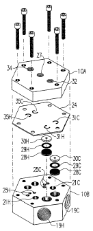
The control block assembly 10 as shown in figures 3 and 4 consists of a cover
block
10A and a main body 10B and when assembled they retain filter elements 28C and
28H, o-
ring seals 29C and 29H, port washers 30C and 30H and a diaphragm 24
constructed of a
flexibly resilient material, common to both diaphragm gate valves 22C and 22H
(see also
figure 2) and one way valves 31 C, 31 H, 35C and 35H.
3
As shown in Figures 2 and 6, in the closed position of the faucet control
assembly
hot and cold water flow through the control block 10 is blocked by the
diaphragm 24 of
diaphragm gate valves 22C and 22H when sufficient pilot or operating water
pressure is
delivered concurrently into respective pilot water chambers 26C and 26H of the
diaphragm
gate valves, thereby seating portions of the diaphragm against the inlet ports
21 C and 21 H
and outlet ports 25C and 25H. In the open position of the faucet control
assembly (see
also figure 5), pilot water pressure in the pilot water chambers 26C and 26H
is vented to
atmosphere, thereby unseating the diaphragm. This permits water flow between
the inlet
and outlet ports 21 C, 21 H and 25C, 25H of both diaphragm gate valves 22C,
22H. Cold
io and hot water can then pass through manifolds 36C and 36H and main outlet
ports 37C
and 37H respectively and directed through onward by known conduits to the
faucet 17.
As shown in Figures 2, 5 and 6 pilot water pressure is controlled by the three-
way
valve 14, in the first position of the three-way valve (see Figure 6), pilot
water is supplied to
a normally open port 34 of the three-way valve and routed through a common
port 35 and
the through flexible conduit 12, into a manifold port 27 from where it is
diverted into the
diaphragm pilot chambers 26C and 26H. Pilot water is delivered to the three-
way valve
from the control block 10 through pilot pressure ports 23C and 23H, filter
elements 28C
and 28H, port washers 30C and 30H and one way valves 29C and 29H. Cold and hot
water is combined in a manifold port 32, and passes through the flexible
conduit 11 to the
2o three way valve 14.
In operation of the faucet control assembly, with reference to Figure 2 and 5,
an
externally applied force 33 urges the three way valve 14 to its second
position venting pilot
pressure from the pilot chambers 26C and 26H of diaphragm gate valves 22C and
22H into
manifold port 27 through the flexible conduit 12 and the common port 39 of the
three-way
valve, out the normally closed port 40 through flexible conduit assembly 13
into manifold
port 34 and through one way valves 35C and 35H output manifolds 36C and 36H
and main
outlet ports 37C and 37H (see also Figure 5) into the faucet 17. Thus the
pilot water
pressure is released to atmosphere, provided at least one valve in the faucet
is set open.
In this embodiment the relative flow settings of hot and cold water valves in
the
so typical faucet will not affect the operation of the faucet control
assembly. Pilot water
pressure is vented to atmosphere into either hot or cold or both portions of
the faucet from
the one way valves 35C and 35H. Both pairs of one way valves 31 C and 31 H and
35C and
35H respectively block cold and hot water cross-flow in the input and output
portion
respectively of the control block 10. The operation of the faucet control
assembly is
unaffected by variations in pressure between the hot and cold supply. The
higher pressure
will always be applied as the pilot pressure thereby assuring closure of the
valve. Further,
the incorporation of filter elements 28C and 28H in the initial pilot water
flow path prevents
4
w ~ 21U9~84
fouling of control elements in the control block 10 and the valve 14 by water
bom pollutants
and debris thereby reducing potential valve failure.
Various changes, adaptations and modifications may be made in the details of
construction, design and layout of the above described embodiment of this
invention
without departing from the spirit thereof. These may include various
mechanical
arrangements so designed to operate the three-way valve by knee, foot or
elbow,
combined with various mechanical latching-features for manual operation of the
faucet or a
push on or a push off feature. Also it may be desirable to divide the control
block into
separate cold and hot blocks to ease installation in some plumbing
arrangements. In such
1o an embodiment (not shown) the respective manifold ports of the separate
control blocks
are interconnected by appropriate conduits to the three way valve. The control
block may
also be integrated in various embodiments directly into a faucet or shower
assembly.
Further, it may be desirable; such as in an integrated faucet assembly to
control the
volume or rate of water flow through the diaphragm gates valves. This may be
accomplished by a means which allows for adjusting volume of the chambers of
the
diaphragm gate valves thereby constricting the passage of water therethrough.
One
embodiment of such a means is shown in Figure 7. The chamber 26 of the
diaphragm gate
valve 22 is constructed in an appropriate manner to accommodate a plunger 50
moveable
within the chamber and acting upon the diaphragm 24. An "O" ring 51 is used as
a means
2o to seal the chamber from atmosphere with the application of pilot water
pressure through
manifold port 27 wherein the diaphragm gate valve operates as previously
described. The
plunger is mechanically urged by an eccentric cam lever assembly 52 to various
positions
when a force 53 is applied thereto variably constricting or stopping the flow
of water
between the inlet port 21 and outlet port 25 of the diaphragm gate valve.
It may also be desirable to use a two way valve in lieu of the three way valve
14 to
vent pressure from the pilot chambers 26C and 26H of the diaphragm gate valves
22C and
22H. This can be accomplished with the addition of one or more orifices or
constrictions
placed in the flowpath of the pilot water circuit between the pressurized
water supplies 16C
and 16H and the chambers 26C and 26H of the diaphragm gate valves 22C and 22H.
The
3o use of an appropriate constriction (approximately .010 of a inch in
diameter) creates a
pressure differential between the supply pressures and atmosphere sufficient
to unseat the
diaphragm thereby permitting water flow through the diaphragm valve block.
s