Note: Descriptions are shown in the official language in which they were submitted.
1 -
SPEED-INCREASED SMALL BOAT
BACKGROUND OF THE INVENTION
The present invention relates to a speed-increased
small powered boat such as racing boats, high-speed fisher-
boats, motorboats for sportfishing and the like. More
particularly, the invention relates to a means to increase
the speed of a small powered boat, which proceeds at such
a high speed that the waterline of the boat body varies
depending on the speed of the boat, by suppressing the wave-
making resistance.
Needless to say, any ships or boats proceeding afloat
on the surface of water produce waves so that a major
portion of the energy output of the engine is lost against
the wave-making resistance so that the maximum speed of 'the
vessel is limited thereby since the wave-making resistance
is rapidly increased as the speed of -the vessel is
increased.
The wave-making resistance here implied is the
resistance caused by a gravity wave produced as a result of
proceeding of a vessel afloat. The most important factor
affecting the wave-making resistance is the so-called Froude
number which is a hydrodynamical parameter as the ratio of
the force of inertia and the gravity.
Accordingly, it is natural that the wave-making
resistance could be decreased when the gravity of the vessel
per se is decreased. In this regard, various attempts and
proposals have been made in the prior art. For example,
a proposal is made in Japanese Patent Publications 55-15349
and 48-36667, according to which the ship hull is provided
with a large number of air-jet openings or holes on or near
the ship bottom and compressed air is ejected therefrom into
the water to form bubbles therein so that 'the ship body
receives an increased buoyant force.
Setting aside submarine boats having no free surface
which proceed with the body entirely submerged, this method
of bubble formation in water has no effect to decrease the
- 2 -
wave--making resistance without reducing occurrence of waves
due to proceeding of 'the ship afloat on the water surface.
Moreover, -the ship running on the mass of bubbles is under
a risk of eventual capsizing when the speed thereof ex<:eeds
a certain upper limit. Therefore, this method of air--jet
bubbling is not practical if not to mentian the cost
therefor.
Alternatively, Japanese Patent Kokai 60-33185 proposes
a method in which compressed air is ejected into the water
in front of the proceeding ship to praduce a water mass
containing numberless bubbles by which the ship receives
a decreased resistance from water. This method is also not
practical because of the great investment for the air
compressor and other accessories far ejecting compressed
air as well as the very large energy consumption for the
ejection of the compressed air again st water pressure.
The inventors have previously proposed, in LJ.S. Patent
5,088,433, a simple but very efficient means to suppress
the wave-making resistance on a ship body proceeding afloat.
Namely, the wave-making resistance on a proceeding ship can
be greatly decreased by providing the ship hull with at
least one pair of fins mounted on the hull surface at
symmetrical positions each extending above and below the
waterline, each fin being fixed to the ship hull at the
front end line thereof without leaving a gap opening
therebetween and the rear end of the .fin outwardly extending
to make a specified fin-mounting angle with the hull
surface.
This means is indeed very effective when the fins are
installed on the ship hull of a relatively large vessel of
which the depth of the waterline little depends on 'the speed
of the vessel. When this means is applied to a relatively
small powered boat of high speed such as racing boats,
however, the effect of wave-making resistance suppression is
not always quite satisfactory since the depth and direction
of the waterline are greatly changed depending an 'the speed
of the boat.
_ 3 -
SUMMARY OF THE INVENTION
The present invention accordingly has an object to
provide a novel and efficient means to decrease 'the wave-
making resistance working on a boat proceeding at a high
speed, of which the depth and direction of the waterline
are subject to changes depending on 'the speed of the boat,
regardless of the speed of the boat up to the highest speed.
Thus, the present invention provides a high-speed
powered boat which is provided on 'the side surfaces of the
boat hull, symmetrically relative to the centerline of tha
keel on the bcat bottom, with a plural number of fins, each
fixed along the front end line thereof to the side surface
of the boat hull without leaving a gap opening therebetween
and the rear end thereof outwardly extending to make a
specified fin-mounting angle with 'the hull surface, arranged
in at least two rows on each of the side surfaces of the
boat hull, each of the fins in the uppermost row extending
above and below the waterline made when the boat is
stationary or proceeding at an intermediate speed up to the
highest and each of the fins in the lowermost row extending
above and below the waterline made when the boat is
proceeding at the highest speed.
Further, an additional advantage is obtained by
providing a stem edge guard, which outwardly extends toward
the stern to make an angle with each of the side surfaces
of the boat body, along the stem edge between the points
corresponding to the waterlines when the boat is proceeding
at the highest speed and when the boat is stationary or
proceeding at an intermediate speed up to the highest speed.
BRIEF DESCRIPTION OF THE DRA'NING
Figure 1 illustrates the flow line of a water stream
around a stationary body held in the stream.
Figure 2 illustrates the flow line of water along a
pair of fins on a boat body according to the invention.
Figure 3 is a plan view of the bottom of a boat showing
three waterlines A, B and C on each side.
- 4 -
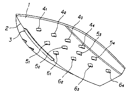
Figure 4 is a perspective bottom view of a boat
according~to the invention provided with three rows of fins
on each side and a stem edge guard.
Figures 5a, 5b and 5c are each a perspective view of
a single fin.
Figure 6 is a perspective view of a single fin having
a sawtoothed rear end line.
Figure 7 is a perspective view of a stem edge guard
demounted from the boat body.
DETAILED DESCRIPTION OF THE PREFERRED EMBODIMENTS
As is defined above and illustrated in the accompanying
drawing, the high-speed powered boat of the present inven-
tion is characterized by a plural number of fins provided on
the side surfaces of the boat hull, symmetrically relative
to the centerline of the keel on the boat bottom, each fin
being fixed along the front end line thereof to the side
surface of 'the hull without leaving a gap opening there-
between and the rear end of the fin outwardly extending to
make a specified fin-mounting angle with the hull surface,
arranged in at least two rows on each of the side surfaces
of the boat hull, each of the fins in the uppermost row
extending above and below the waterline made when the boat
is stationary or proceeding at an intermediate speed up to
the highest and each of the fins in the lowermost row
extending above and below the waterline made when the boat
is proceeding at the highest speed.
According to the hydrodynamics, as is well known, any
actual fluid has viscosity and compressivity so that, when
a body is held in a stream of a fluid, the viscosity of the
fluid causes a velocity distribution in the fluid due to the
wall-surface friction and, as is shown in Figure 1, a break-
away portion "a" and back-wash portion "b" are formed in the
flow line pattern around the body. The situation is similar
when the fluid is stationary and the body therein is moved.
This fact has led to the improvement proposed in U.S. Patent
5,088,433 according to which, when a fin extending outwardly
- 5 - X109901
toward the rear end is provided on 'the side surface of the
boat to extend above and below the waterline of the boat,
as is illustrated in Figure 2, a break-away portion "a" is
formed at the rear end of the fin while a back-wash portion
"b" is formed between the rear end of the fin and the
surface of the body. As a consequence, the wave formed by
the proceeding boat is converted into a turbulent flow as it
passes the rear end of the fin resulting in quenching of the
wave or suppression of the wave-making resistance.
When a plural number of pairs of such fins are provided
symmetrically on the side surfaces alon g the waterline from
the bow to the stern, the wave-making resistance caused by
navigation of the boat on water can be stepwise suppressed
by the successive pairs of the fins so that the boat can be
freed from speed reduction due to the wave-making resistance
to a considerable extent.
It is known, however, that the depth and direction of
the waterline are subject to changes depending on the speed
of the boat, especially, when the boat is a relatively small
boat of very high speed such as racing boats, high-speed
fisherboats, motorboats for spor~tfishing and the like. As
is illustrated in Figure 3, the waterline of the boat is
deepest as is indicated by the chain line A, for example,
when the boat is stationay while the waterline moves on the
side surface 1 to the chain lines B to C symmetrically
relative to the keel centerline 2 as the speed of the boat
is increased, usually, with the bow of the boat raised
relative to the stern. Accordingly, a pair of fins
installed on both side surfaces of a boat along a single
waterline indicated, for example, by the chain line A would
no longer be effective when the boat is navigating at a high
speed.
In this regard, the present invention proposes to
provide pairs of fins in at least two rows, or in three rows
in Figure 4 including the fins 4,, 4~, 4s and 44 in the
uppermost row, 5, , 52 , 53 and 54 in the second row and 6~ ,
52, 6g and 69 in the lowermost row, of which each row is
2 ~. 0 ~'~ ~ ~.
along a waterline A, B or C in Figure 3 being changed
depending on the speed of the boat. Preferably, each of
the fins in the lowermost row extends above and below the
waterline made when the boat is proceeding at the highest
speed. On the other hand, the uppermost row need not
correspond to the stationary waterline of the boat but can
be along a waterline when the boat is proceeding at an
intermediate speed up to the highest because the advantage
obtained by providing the fins according to 'the invention is
relatively small when the boat is proceeding at a low speed.
Assuming that the highest speed of the boat is 50 knots, for
example, the lowermost row of the fins 6,, 6z, 69 and 69 is
preferably along the waterline which is made when the boat
logs 50 knots but the uppermost and the second rows each can
be along the waterline when the boat is proceeding, for
example, at 20 knots and 35 knots, respectively.
The form of each of the fins is not particularly
limitative provided that the front end line thereof is
curved to just fit the curved side surface of the boat hull
on which the fin is mounted. For example, the fin can be
square, rectangular, trapezoidal, triangular, pentagonal
semicircular, sector-formed and the like. The material of
the fins is also not limitative including metals, plastics,
woody materials, ceramics and the like if a mechanical
strength as desired can be obtained therewith. The
dimensions of each fin are selected depending on various
factors including the size of the boat, expected highest
speed of the boat and so on. As an example, a rectangular
fin may have a vertical length of 10 to 50 cm and a
horizontal length of 15 to 70 cm.
Figures 5a, 5b and 5c each illustrate 'the mounting
fashion of a rectangular fin 4 on the boat hull 9. As is
illustrated in Figure 5a, the rectangular fin 4 is fixed in
a cantilever fashion to the boat hull 9 by rivetting along
the front end line 7 while the body of the fin 4 extends
outwardly toward the rear end making an angle a therewith so
that the rear end line $ of the fi.n 4 is apart from the hull
_ 7 _
surface 9. The angle a is in the range from 2° to 25° or,
preferably, from 5° to 15°. In Figure 5b, the rear end 8
of the fin 4 is extended portionwise at the upper and lower
parts and the extended portions 11, 11' are bent and welded
to the hull surface 9 like a stay member so as to obtain a
reinforcing effect of fin mounting. In Figure 5c, each of
the gap openings formed between the upper and lower end
lines of the fin 4 and the hull surface 9 is closed by
providing a narrow triangular stay 12 making a pocket 10
between the fin 4 and 'the hull surface 9 so as to obtain
a further increased reinforcing effect of fin mounting. It
is sometimes advantageous to have such a design that the fin
mounting angle a is variable.
Figure 6 illustrates a fin 4 similar to that illus-
trated in Figure 5b. In this fin 4, the rear end line is
not a straight line as in Figure 5b but is shaped in a
sawtoothed line 8' by which an additional advantage is
obtained that the bubbles eventually formed along the rear
end line 8' of the fin are divided so as to exhibit a
rectifying effect against occurrence of a turbulent flow.
In addition to the rows of fins installed on the side
surfaces of the boat body, an additional effect of wave-
making resistance suppression can be obtained by providing
the bow of the boat with a stem edge guard 3 as is illus-
trated in Figures 3 and 4 along the centerline 2 of the
keel. Figure 7 illustrates a perspective view of a stem
edge guard 3 as demounted from the boat body. The stem edge
guard 3 is an elongated plate bent along the centerline 14
to make left and right wings 17, 17' having a doglegged
cross sectional configuration and fixed to the stem line of
the boat at the upper end 13 and along the center line 14
symmetrically relative to the center line 2 of the boat keel
reaching the waterline made when the boat is proceeding at
the highest speed in such a fashion that the side lines 15,
15' are each apart from the side surface of the boat body.
It is preferable for reinforcement of mounting that several
stays 16, 16' are provided between the side lines 15, 15'
of the stem edge guard 3 and the surface of the boat body.
It is of course optional, in place of -the separate stays 16,
16', to have the wings 17, 17' are extended portionwise and
bent toward the body surface where the extended portions
of the wings are fixed thereto by welding. It is of course
optional 'that the wings 17, 17' are prepared as separate
members and they are mounted individually to the stem of the
boat.
The stem edge guard 3 should have a length sufficient
to cover the range corresponding to 'the centerline 2 between
the highest and lowest waterlines. The actual length and
width thereof naturally depend on the size of the boat, for
example, in the range from 2 to 10 meters for the length and
from 10 to 50 cm for the width. It is preferable that the
wings 17, 17' of the stem edge guard 3 extend outwardly such
th at each of the side lines 15, 15' is apart from the hull
surface at a distance of 2 to 10 cm. If necessary, this
distance between the side line 15 or 15' and the hull
surface is gradually decreased from the front end toward
the rear end.
When a small high-speed powered boat is provided with
fins in a plural number of rows and with a stem edge guard
according to the invention, a great effect of wave-making
resistance suppression can be obtained irrespective of the
speed of the boat so that the speed of the boat can be
increased by 5 to 20~ as compared with a conventional boat
of the same model assuming the same power output of the
engine. Alternatively, a considerable saving in the fuel
cost can be obtained with the inventive boat as compared
with a conventional boat of 'the same model proceeding at the
same speed. Moreover, the boat according to the invention
is advantageous in respect of the comfortableness of the
crews and passengers on board since a stabilizing effect
can be obtained in the boat according to the invention even
on a stormy sea.
In the following, the inventive boat is described in
more detail by way of examples.
_ g
Example 1.
A water tank test was undertaken with two model boats
each having an overall length of 1 meter in a water tank of
meters by 5 meters wide. The two model boats floating
5 at about the center part of the water tank in parallel with
each other were each towed at the bow with a rope through
a tension gauge in the direction along the longer side of
the water tank.
One of the two model boats, the other being for
10 control, was provided with 12 fins on each side in three
up and down rows each with four fins as is illustrated in
Figure 4. The fins were made from a 2 mm thick plate of a
polyvinyl chloride resin and had a vertical length of 4 cm
and a horizontal length of 5 cm. The foremost fins in the
uppermost, middle and lowermost rows were fixed to the hull
surface at such positions that the front end lines of the
respective fins were 15 cm, 30 cm and 45 cm, respectively,
apart horizontally from the bow head. The rear end line of
each fin was 0.5 cm apart from the hull surface so that the
fin mounting angle was 6°. In each of the rows, 'the four
fins were fixed to the hull surface with a pitch of 25 cm.
The fins of the uppermost row were fixed to the hull surface
along the waterline of the model boat when the boat is
stationary on the water surface while the fins of the second
and lowermost rows were fixed along such waterlines 6 cm and
13 cm, respectively, below the stationary waterline.
Separately, the same model boat was provided with a
stem edge guard having a length of 45 cm and a width of 3
cm along the centerline between the points apart from the
head of the bow by 5 cm and 50 cm. The distance between
each side line of the stem edge guard and the hull surface
was 0.5 cm all over the whole length thereof.
A parallel water stream was generated by means of a
water-jet pump in the water tank in the direction from the
bow to the stern of the towed model boats at varied flow
velocities and the tension load on the towing ropes was
-
determined by means of the 'tension gauge. The results are
shown in Table 1.
T a b 1 a 1
Water stream velocity, Load, kg
meter/second with fins no fins
3.0 1.1 2..1
4.0 1.6 2.4
5.0 2.2 3.0
6.0 2.5 3.8
Example 2.
A real boat test was undertaken as a control with a
motorboat (Model Yamaha SR-21) having an overall length of
6.65 meters and an overall width of 2.41 meters and weighing
820 kg equipped with an outboard engine of 220 horsepower.
On a still-water area of the sea under the oceanographic
conditions of a wind velocity of 0.5 m/second (1.1 miles/-
hour) and a wave height of 10 cm, the boat was driven at the
full engine output repeatedly back and forth between 300
meters apart posts and the times taken for the 300 meters
runs were recorded to calculate the average speed of the
boat, which was 39 knots.
Similarly to the model boat test in the water tank
described above, the motorboat was provided with 12 fins
on each side in three rows each with four fins as is
illustrated in Figure 4. The fins were made from a 3 mm
thick steel plate and had a vertical length of 18 cm and
a horizontal length of 22cm. The foremost fins in the
uppermost, middle and lowermost rows were fixed to the hull
surface at such positions that the front end lines of the
respective fins were 1.5 meters, 2.0 meters and 2.5 meters,
respectively, apart horizontally from the bow head. The
rear end line of each fin was 1.0 cm apart from the hull
- 11 -
surface so that the fin mounting angle was 3°. In each of
the rows, the four fins were fixed 'to the hull surface with
a pitch of 60 cm. The fins of the uppermost row were fixed
to the hull surface extending above and below 'the waterline
of the boat when the boat is stationary on the water surface
while the fins of the second and lowermost rows were fixed
extending above and below such waterlines 20 cm and 30 cm,
respectively, below the stationary waterline.
Further, the bow of the boat was provided with a stem
edge guard having a length of i50 cm and a width of each
wing of 22 cm mounted thereon with the front end thereof at
a position of 50 cm apart from the bow head. The stem edge
guard had such an apening angle that each of the side lines
thereof was 1.5 cm apart from the hull surface.
The motorboat thus provided with the fins and the stem
edge guard was subjected to 'the running test in the same
manner as above to find that the highest velocity was 44
knots. In addition, a remarkable decrease is noted in
rolling of the boat indicating a stabilizing effect obtained
according to the invention.