Note: Descriptions are shown in the official language in which they were submitted.
WO 92/22034 PCl'/US92/04396
109~17
:`
~r
t:'~
, ~`
A ~IGII--PERFORNANCE ~08T INTERFACE FOR AT~l NEI~ORR8
FIELD OF T~E INVENTION
~` The present invention generally relates to the
fields of computers and communications networks. More
~, 5 particularly, the present invention relates to an
interface between a network element, such as a host
~ computer, and a telecommunications network.
Pll BACRGRC)llND OF T~E l:~JVE~ ON
Computer technology is reaching the point where
a host computer system, such as a workstation, will be
able to produce or consume data at close to 1 Gbps. High
speed telecommunications networks (such as the Broadband-
~,4 Integrated Digital Services Network (B-ISDN)) capable of
I5 transporting data at that speed are also becoming
available. However, a major bottleneck exists at the
interface between the host computer and the network. Two
main functions are performed at this point:
.
1. data is converted between a format useful
to the host computer and the format that is required by
the network;
2. data is moved between the host computer's
memory and the network. See copending application Serial
No. 660,637, filed February 25, 1991.
The amount of processing power required to
perform those functions at a speed sufficient to load a
Gbps network is unavailable in most computers. Previous
approaches to solving this problem employ front-end
"protocol engines" to off-load some of the processing from
the host computer. See e.g., E. A. Arnould, et al., "The
~ W092/220~ PCT/USg2/04396 -
2109917
~ 2 ~
>r
Design of Nectar: A Network Bac~plane for a Heterogeneous
- Multi-computer," Technical Report CMU-CS-89-101, Computer
Science Dept. , C~U, (January, 1989); R. Reach, "Ultranet:
An Architecture for Gigabit Networking." Local Computer
Networks, pp. 232-248, Minneapolis, MN, (October, 1990);
H. KanaXia and D. Cheriton, "The VMP Network Adapter Board
(NAB): Higb-performance Network Communication for
Multiprocessors," Proc. ACM SIGCOMM '8~, pp. 175-187,
Stanford, CA (August 1988); H. Kanakia, ~High Performance
Host Interfacing for Packet Switched Networks, n Ph.D.
thesis, Stanford University, (November, 1989); G. Chesson
"XTP/PE Overview, n Proc. 13th Con. on Local Computer
Networks, pp. 292-296, Minneapolis, MN, (October, 1988).
In addition, previous approaches to this problem are based
on very large packet sizes (1 Kbyte to 32 Kbytes), thus
those approaches are not suitable for use with a
telecommunications network that utilizes the Asynchronous
Transfer Mode (ATM) transmission technique.
According to the ATM technique, data is
transmitted in 53-byte packets called cells. With 53-byte
cells, headers must be generated and processed at a far
more rapid rate than when packets are 1-32 Kbytes. The
prior art approaches~to interfacing a host computer to a
telecommunications network at gigabit speeds do not
process headers fast enough to be useful to interface a
computer with an ATM network.
The ATM is a transmission technique for
transmitting data belonging to a variety of applications
across a network. An important advantage of the ATM
technique i8 that it provides a single transmission format
by which data from a variety of network element sources
(such as voice, high definition video, and computer and
terminal connections) may be transmitted in a single
transmission format, rather than requiring separate
transmission formats and processing facilities for each
type of data.
~:
~ ' .
~092/22034 PCT/USg2/04~K
2109917
- 3 -
Each 53-byte ATM cell comprises 48 bytes of
payload and a 5-byte ATM header. The header includes a
Virtual Channel Identifier (VCI) that indicates the
particular channel or connection to which the cell
belongs; it is used to direct the cell at the various
switching po~nts in the network. The ATM cell header also
includes a Cyclic Redundancy Check (CRC) byte. The 48-
byte payload may also contain a 4-byte Adaptation Layer
header the contents of which depend on the application.
The ATM cells are transmitted in slots defined
in the pay~oad fields of, e.g., the frames of the SONET
STS-3c signal (155 Mbps) or the SONET STS-12 signal (622
Mbps), which may be formed by multiplexing four STS-3c
signals. An OC-48 optical signal may be used to achieve
transmission rates of over 2 Gbps.
~ he ATM technique is referred to as being
asynchronous because the slots in the frames of the
signals are not reserved for the cells of particular
applications, but instead are filled by the cells of
various applications in accordance w~th the various
applications' current demand for 810ts and the current
availability of slots. The ATN transmission technique is
expected to be the standard for providing broadband
telecommunications services through a broadband trunk and
exchange network such as the B-ISDN.
As mentioned above, the interface between a host
co~puter and the network presents a severe bottleneck when
attempting to move data at Gbps speeds. Interface (or
protocol) architectures can be viewed as a stack of
layers. The ISO OSI model, for example, consists of seven
layers. The ~highest" layer, the application l~yer, is
the application program interface (API) to the network.
The physical layer is the hardware that connects the node
to the network medium. The intervening layers perform
additional functions, such as reliable delivery,
connection management, etc., as required by the API. See,
e.g., A. Tannenbaum, Computer Networks.
W092~220~ PCT/USg~W3~
2109917
- 4 -
There are several research projects directed to
providing high-performance host interfaces. The ma~or
difference between the respective implementations of the
projects is the number of protocol processing functions
S performed by the host interface. One important focal
point has been the development of interfaces that
accelerate transport protocol processing. See M.
Zitterbart, "High-Speed Transport Components," IEEE
Network, pp. 54-63 (January, 1991).
Kanakia and Cheriton's VMP Network Adapter Board
serves as a hardware implementation of Cheriton's
Versatile Message Transaction Protocol (VMTP). See H.
Xanakia and D. Cheriton, "The VMP Network Adapter Board
(NAB): High Performance Network Communication for
Multiprocessors, n Proceedings, SIGMETRICS '88 (1988).
Abu-Amara et al. are capable of targeting any
set of protocol layers (to the degree that they can be
precisely specified) with their PSi silicon compiler
approach. With that method, the protocol is specified
using a symbolic programming language and mask
descriptions for fabrication process layers are generated
as output of a compiler. The masks are then used to
create custom hardware. see H. Abu-Amara, et al., ~PSi: A
Silicon Compiler for Very Fast Protocol Processing,"
Protocols for High Speed Networks, ed. R.C. Williamson,
North-Holland (1989).
The Nectar Communications Accelerator Board
(CAB) may be programmed with various protocols. The CAB
communicates with the host memory directly and the
programmability can conceivably be uæed by applications to
customize protocol processing. s~e E. A. Arnould, et al.,
"The Design of Nectar: A Network Backplane for
Heterogeneous Multicomputers," Proceedings, ASPLOS-III pp.
205-216 (April, 1987).
Cooper et al. have reported that TCP/IP and a
number of Nectar-specific protocols have been implemented
on the CAB connected to Sun-4 processors. See E. Coopèr,
~0g2/220~ PCT/US92/04396
21~9317
et al., "Protocol Implementation on the Nectar
Communication Processor," Proceedin~s, SIGCOMM '90,
Philadelphia, PA pp. 135-144 (September 24-27, 1990).
Davie of Bellcore has reported on a host
interface designed for the TurboChannel bus of the Dec
Station 5000 workstation. That design relies on an Intel
80960 RISC microController to perform the protocol
processing and flow control for a trunk group of four STS-
3c lines (622 Mbps). See B. S. Davie, "Host Interface
Design for Experimental, Very High Speed Networks, n Proc.
Compcon Spring '90, San Francisco, CA pp. 102-106
(February 1990); B. S. Davie, "A Host-Network Interface
Architecture for ATN," Proceedings, SIGCOMM 1991, Zurich,
Switzerland (Sept. 4-6, 1991).
The IBM RS/6000 workstation is one example of a
host computer for which an interface in accordance with
the present invention is suitable. The RS/6000
¦ workstation has a 32-bit MicroChannel bus for I/0
¦ interconnections. Transfers may be either 8, 16, or 32
¦ 20 bits wide. The basic cycle time for the bus is 200ns, but
¦ with data ~treaming a single lOOns ~etup time may be
¦ amortized over many transfers. The streaming operation
starts out as a basic transfer cycle. After the transfer
has been set up, the slave acknowledges that it may
~upport a ~treaming transaction, which enables the master
to then start the 10 Mhz streaminq strobe. A data
transf~r may then be made every lOOns. No addressing
; information is generated by the master while the stream is
in progress. Streaming may be terminated or paused by
either the slave or the master. see H.B. Bakoglu, et al.,
The I8N RISC System/6000 Processor: Hardware Overview,"
: IBM Journal of Research and Development 34(1), pp. 12-22
(January, 1990).
A goal of the present invention is to provide an
interface between a network element and a
telecommunications network that operates at near Gbps
speeds and that is compatible for use with the ATM
WO 92/220~ ` !, , PCT/US92/04396
" ~ , .
2i09'.J1~ ` - 6 -
transmission technique. A further goal of the present
invention is to provide an interface that is capable of
receiving data from a network element, such as a host
computer, and segmenting it into ATM cells for
S transmission over a telecommunications networ~. A still
further goal of the present invention is to provide an
interface that is capable of receiving and reassembling
segmented ATM data for use by the network element. A yet
further goal of the present invention is to provide a
high-performance interface for an IBM/6000 workstation
host in an ATN telecommunications network.
8~MMARY OF THE INVENTION
These goals are achieved by the present
invention, according to which a reassembler for
reassembling received ATM data that has been segmented
into a plurality of cells, each of which comprises a VCI
and a cell body, comprises first means for separating each
cell body from its corresponding VCI and determining
respective linked list reference addresses for the VCIs,
Reassembly Buffer means for storing the cell bodies, and
Linked List Nanager means for storing linked list data
indicative of addresses at which the cell bodies are
stored in the Reassembly Buffer means.
.
In one preferred embodiment the Linked List
Manager means comprises Pointer Table means for storing
the linked list data and Linked List Controller means for
removing linked list data from the Pointer Table means and
writing/reading linked list data to/from the Pointer Table
means.
In another preferred embodiment the Reassembly
Buffer means comprises Reassembly Memory means for storing
the cell bodies and Dual Port Controller means for
writing/reading cell bodies to/from the Reassembly Memory
means.
In yet another preferred embodiment the first
means comprises Cell Manager means for separating each
~09~22034 PCT/US92/~396
2,1~)ggl~
_ 7 _
cell body from its corresponding VCI and detecting whether
- the VCI has been corrupted, CAM means for storing the VCIs
and providing pointers into the linked list data, and VCI
Lookup Controller means for writing VCIs to the CAM means.
In yet another preferred embodiment the first
means, Reassembly Buffer means and Linked List Manager
means are adapted for parallel operation.
The present invention also encompasses
interfaces that comprise Segmenter means for segmenting
data from a network element into a plurality of ATM cells
and transmitting those cells onto the ATM network, and
Reassembler means in accordance with the foregoing
description for reassembling received ATM data.
The present invention also encompasses systems
comprising a network element, a telecommunications
network, and reassembler means, in accordance with the
foregoing description, for -eceiving and reassembling ATN
data from the network.
In one specific embodiment, the network element
is another network.
Preferred embodiments of the invention provide a
"common denominator" set of services that may be used to
support a complete range of higher level protocols. Those
services have been inexpensively and efficiently
implemented by limiting the interface to a collection of
base services. Other features of the invention are
described below in connection with the detailed
description.
BRIEF DE8CRIP~ION OF T~E DRAWING8
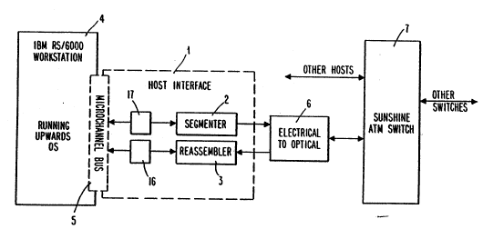
Figure 1 is a partial block diagram of a
computer network in accordance with the present invention.
Figures lA is a block diagram of an interface 16
of Reassembler 3 of Host Interface 1 of Figure 1.
Figures lB is a block diagram of an interface 17
of Segmenter 2 of Host Interface 1.
W09~220~ PCT/US92/04396 .
~ .'t.,5 91~ ~ 8 -
i Figure 2 is a block diagram of the Reassembler 3
of the computer network depicted in Figure 1.
Figure 3 i8 a block diagram of the Linked List
Manager 10 of the Reassembler 3.
S Figure 3A is a state machine diagram for the
Linked List Controller 18 of the Linked List Nanager 10.
. Figure 3B depicts the format of the lin~ed lists
~tored in, and a memory map for, the Pointer Table memory
30 of the Linked List Manager 10.
'~0 Figure 4 is a block diagram of the Dual Port
~ Reassembly Buffer 12 of the Reassembler 3.
j Figure 4A is a state machine diagram for the
Dual Port Reassembly Buffer 12.
Figure 5 is a block diagram of the SONET
Interface and VCI Lookup Controller block 14 of the
Reassembler 3.
Figure SA is a state machine diagram for the VCI
Lookup Controller 52 of block 14.
Figure SB is a state machine diagram for the
Cell Manager 56 of block 14.
Figure 6 is a block diagram of the Segmenter 2
of the computer network of Figure 1.
. DETAILED DE8CRIPTION OF PREFERRED E~BODIM~WT~
The following detailed description of the
preferred embodiment refers to the attached drawings and
i8 intended to make the invention properly understood by
way of example without any limitation being implied.
- Figure 1 is a partial block diagram of a
computer network in accordance with the present invention.
¦ 30 The invention i8 embodied in a host interface 1 comprising
a Segmenter 2, NicroChannel interface card 16, Reassembler
3 and MicroChannel interface card 17 (16 and 17 are shown
in Figures lA, lB), which may be combined on one wire-
wrapped card if double-sided surface-mount fabrication
techniques are used. The MicroChannel interfaces 16, 17
are based on a Chips and Technologies 82C612 DMA slave
~W092~22034 PCT/USs2/04396
2109917
interface. Additional logic, which includes one EPM5128
- and two EPM5032 programmable logic devices (PLD~),
provides the capabilities of streaming bus mastering and
extensive address decoding. Those capabilities are
important because the MicroChannel interface card provides
a burst bus bandwidth of 320 Mbps, as opposed to the 160
Nbps bandwidth provided by typical DNA interfaces.
The host interface 1 is connected to a Sunshine
ATN switch 7 via an electrical to optical converter 6 and
lo an lBN RS/6000 workstation 4 via a MicroCh~nnel bus 5.
The interface employs SONET framers of the type described
in T. J. Robe and K. A. Walsh, "A SONET STS-3c User-
Network Interface IC," Proceedings, Custom Integrated
Circuits Conference, San Diego, CA (May, 1991).
Referring now to Figure 2, which provides an
overview of the Reassembler 3, the three boxes 10, 12, 14
respectively labeled Linked List Manager, Dual Port
Reassembly Buffer and SONET Interface and VCI Lookup
Controller are capable of concurrent operation once they
are initialized and configured. This concurrent operation
may be exploited to allow reassembly of an ATN cell in
much less than the 2.7 microsecond cell transmission time.
ATM cells are received by the SONET Interface
and VCI Lookup Controller block 14. Block 14 splits the
cells' headers from the corresponding cell bodies and
passes the VCIs to the Linked List Nanager 10 and the cell
- bodies to the Dual Port Reassembly Buffer 12. The Linked
List Manager 10 creates a linked list for each VCI that
identifies the locations in the Dual Port Reassembly
Buffer 12 of all cell bodies associated with that VCI.
~ Figure 3 is a block diagram of the Linked L~st
Manager 10. The Linked List Manager 10 is capable of
performing a number of operations on the linked list data
(depicted in Figure 3B) to effect reassembly. The use of
linked list data structures allows memory to be
dynamically assigned to incoming ATM cells and provides a
first in-first out (FIFo) gueue for the cells of a
W092/220~ PCT/USg2/043g6
' "'' 2Ib99l7 ' - 10
particular VCI. The memory allocation is dynamic because
incoming cells are placed into nodes that are removed from
a free list (discussed below) and added to the linked list
for the particular VCI. In this way, VCIs that are more
active are allotted more memory than less active VCIs.
Moreover, memory may be deallocated as soon as a cell body
has been read. This is accomplished by transferring the
node back to the free list. The FIF0 queuing
characteristic of the linked list structure is important
because the order of cells of a particular VCI must be
maintained.
The linked list data consists of pointers and
cell counts. The cell bodies are stored separately in the
Dual Port Reassembly Buffer 12, which is described below.
The cell body data is separated from the linked list data
to minimize the amount of data movement. This separation
is partîcularly important because it allows linked list
management and data movement operations to be carried out
in parallel. The separation of the linked list and cell
body data wil} become even more important as the network
speed is increased because it limits the degree to which
memory bandwidth 11mitations can throttle the interface.
The Linked List Nanager 10 receives references
to and commands for the manipulation of a particular VCI
from the VCI Lookup Controller 52 (which is part of block
14, Figure 5). It also provides status information for
the host 4 (Figure 1) and addresses in the Reassembly
Buffer 12 to which data is to be moved.
The Linked List Manager 10 is composed of a
Linked List Controller 18, buffers 20, 22 (used for
- configuration), counter 24, and registQrs 26, 28, 32, 34,
36, which are used in managing the linked lists, and a
Pointer Table memory 30 of 8192 (8X) words, which is used
to store the linked list data necessary for reassembly.
The Linked List Controller 18, buffers 20, 22, counter 24,
and registers 26, 28, 32, 34, 36 are provided by an
EPM5128 programmable logic device in the preferred
~WO g2J22034 PCr/US92/043g6
2;llo9sl7
embodiment; the Pointer Table memory 30 is composed of two
8K by 48 MCM6164-45C static random access memories (RAM8).
All of the nodes are as~embled into a linked
list, known as the free list, during initialization.
Operation of the host interface 1 is suspended during
- initialization, during which all pointers and counters
used to keep track of the linked lists are zeroed.
Initialization is performed by the host 4 by requesting a
setup state and writing the appropriate configuration data
to buffers 20, 22.
The free list is a linked list of nodes that are
not currently assigned to a VCI. The free list is defined
by the values stored in locations 2048 and 2049 of the
Pointer Table memory 30 (Figure 3B), which represent the
addresses of the first and last free nodes in the free
node linked list.
Four operations may be performed by the Linked
List Manager 10 after initialization:
1. Cells may be added to the linked list for a
particular VCI.
2. Cell~ may be removed from a VCI's linked
list.
3. A VCI may be cleared, returning all of its
nodes to the free list.
4. A cell count for a VCI may be obtained and
xeturned to the host.
The first two operations pass the Reassembly
Memory 44 address of the cell body that is to be affected
to the Dual Port Controller 46 (44 and 46 part of the Dual
Port Reassembly Buffer 12 and are shown in Figure 4). The
count and linked list associated with that VCI are also
updated.
A first portion (the first lK (1024) words) of
the Pointer Table memory 30 comprises a series of storage
locations for each of the 256 possible VCIs. This
structure is depicted in Figure 3B. For each VCI, the
pointer to the newest cell received (the last cell) is
W092/220~ PCT/US92/'~3
210~`9 17 _ 12 -
stored in a first location, the pointer to the oldest cell
(first cell) is stored in a second location, and the
current count of cells for the particular VCI is stored in
a third location. The respective pointers point to
locations in the linked lists, which are located in the
last 4K of the Pointer Table memory 30. It is useful to
have access to a count of the number of cells available
for a particular VCI in order to gauge the volume of
traffic on that VCI.
A second portion (the last 4K words, locations
4096-8192) of the Pointer Table memory 30 comprises sets
of locations for storing pointers used for the nodes of
the linked lists. Each node physically comprises two
consecutive memory locations beginning on every even
address in the 4K to 8K segment of the Pointer Table
memory 30. The first location of each node stores the
address in (or pointer to) the Reassembly Memory 44
(Figure 4) where the cell body associated with that node
is stored. The value of the first pointer is undefined if
the node is in the empty list (i.e., if the node has not
been allocated to a VCI). ~The second location of each
node stores a pointer to the next node in the linked list.
The value is zero if the node is the last node in the
linked list.
Figure 3A is a state machine diagram for the
Linked List Controller 18.
The Linked List Controller assumes an idle state
(state S31) after reset (state S30).
The Linked List Controller 18 moves to the setup
state (S32) if the host 4 issues a setup command and
specifies setup data to be written into the Pointer Table
memory 30.
The Linked List Controller 18 moves to the
initiate command state (S33) when commands requesting
operation on the linked list of a particular VCI are
passed from the VCI Lookup Controller 52 (Figure 5).
Those commands include commands for removing a cell,
W092/220~ PCT/US92/~3~
21 0991~7
- 13 -
writing (i.e., adding) a cell and reading a cell from a
linked list for a particular VCI.
The Linked List Controller 1~ moves to state S34
when a remove command is issued. In state S34 the linked
list associated with the VCI to be removed is appended to
the free list.
The Linked List Controller 18 moves to state S3s
when a read command is issued. In state S35 the Linked
List Controller 18 locates the first cell reference
structure (oldest cell) in the linked list associated with
the VCI and determines the location of the cell body in
the Reassembly Memory 44.
The location of the cell body is passed to the
Dual Port Controller 46 (Figure 4) in state S39 and the
count (number of cells in the VCI's linked list) is passed
to the host 4 in state S40. Providing the host a count of
the cells associated with a particular VCI allows the
level of activity of that VCI to be judged.
After the count has been provided to the host 4,
the Linked List Controller 18 initiates the operation of a
second state machine, which starts at state S41, and then
returns to the idle state (S31).
The second state machine monitors the host 4 to
ensure that the cell body has been read (state S41) before
the entry in the linked list is deleted in state S42. The
count associated with the VCI is decremented when the cell
is deleted from the linked list. The location of the next
node or ~ell in the linked list is requested once the cell
body has been read. The automatic selection of the next
node will be overridden, however, if the host should
instead decide to read another VCI. The automatic reading
of the next node of a particular VCI significantly
enhances the performance of the Reassembler 3 since a new
transfer into the host need not be initiated for each cell
body.
The Linked List Controller 18 moves to state S36
when a write command is issued. In state S36 the Linked
W092/22034 PCT/US92/04396
210!~917
- 14 -
List Controller 18 writes a new cell body to a reassembly
list and removes the first cell reference structure in the
free list and appends it to the end of the list for the
appropriate VCI.
An error is set in state S37 if the free cell
list is empty.
In state S38, the pointer into the Reassembly
Memory 44 (Figure 4), which is contained in the cell
structure, is passed to Controller 46 and the cell count
for that VCI is incremented. The Linked List Controller
18 thereafter returns to the idle state (S31) to await the
next command.
Figure 4 is a block diagram of the Dual Port
Reassembly Buffer 12 of the Reassembler 3. The Dual Port
Reassembly Buffer 12 is used to reassemble the cell bodies
arriving from the network and store them until the host 4
is ready to process them. When the Linked List Manager 10
has determined the location in the Reassembly Memory 44
for a new cell, that location is written into a register
48, which is associated with an Assembly Counter 50. The
cell body is moved, under the control of the Dual Port
Controller 46 ~which is implemented by an EPM5128
programmable logic device), from the body FIF0 60 of block
14 (Figure 5) to where it is temporarily stored in the 32K
by 32 Reassembly Memory 44 (which is composed of four
MCM6206P45 static RAM devices) at addresses generated by
the Assembly Counter 50. If the Linked List Manager 10
determines the address for another transfer before the
Dual Port Reassembly Buffer 12 completes its current
transfer, the address of the next cell body to be
transferred is stored in Registers 40, 48 until the Dual
Port Reassembly Buffer 12 can attend to the next requested
transfer.
The Dual Port Reassembly Buffer 12 also provides
a means for transferring reassembled data to the host 4.
The Linked List Manager 10 provides the address in the
Reassembly Memory 44 that contains the cell body that is
`W092/22034 PCT/USg2/043~
211~-9 9 1r7
- 15 -
to be transferred to the host 4. The data stream transfer
~ay be initiated when the Reassembly Memory addre~s i8
loaded into Retrieval Counter 42. As soon as a streaming
strobe has been activated, the Retrieval Counter 42
increments its count on the rising edge of the streaming
strobe and the Dual Port Controller 46 reads the
appropriate word from Reassembly Nemory 44 and places it
on the MicroChannel bus 5 via the MicroChannel interface
16.
Figure 4A is a state machine diagram for the two
state machines (the read and write state machines) of the
Dual Port Controller 44.
Each of the two state machines enters its
respective idle state (states S21, S23) after reset (state
S20).
The Dual Port Controller 46 begins a transfer as
soon as it receives a source or destination address from
the Linked List Nanager 10. If a read is requested,
twelve words (48 bytes, one ATM cell) are transferred one
at a time on the falling edge of the streaming strobe
(state S24). `If a write is requested, 48 bytes are read
from the body storage FIFO 60 tFigure 5) and are written a
word at a time into the Reassembly Memory 44 (state S22).
; The Dual Port Controller 46 arbitrates simultaneous read
and write requests. Prefe # nce is given to read
operations.
Figure 5 is a block diagram of the SONET
Interface and VCI Lookup Controller block 14. Block 14
operates as follows:
1. The Cell Manager 56 (composed of an EPM5128
erasable programmable logic device ~EPLD))
~- splits tbe header from the cell body and
calculates the checksum of the header to
~etect possible header corruption.
2. The 16-bit VCI (as specified in the ATM
Standard (see CCITT Study Group XVIII,
"Meeting Report of Subwork Party 8/1 ATM,~
,~ W092/22034 PCT/US92/~
~ 2109gl7
' - 16 -
~, Document 14-E (June 1989))) is extr~cted
3 from the header and loaded into a register
i ~not shown) while the body i~ loaded into
the Body FIF0 60 (composed of a 67C4501
S RAM-based FIF0).
3. The VCI lookup content addressable memory
(CAM) 54 (composed of an Advanced Micro
Devices Am99C10 CAM) locates the VCI and
determines its linked list reference
location.
4. The address of the reference location may
be passed to the Linked List Nanager 10
along with an indication of which linked
' list operation is to be performed.
, The CAM 54 is a 256 by 48 memory device, thus
256 VCIs may be reassembled simultaneously. That number
may be scaled upward by using a different or additional
, CANs.
~ The VCI Lookup Controller 52 (an EPM5128 EPLD)
'~ 20 adds~the VCI to the CAM 54 if the VCI has not b~ien used
,~ ~ beforQ~. The VCI Lookup Controller 52 also locates VCIs
that the~host 4 i8 interested in moving from the
'~ R-assembly 8uffer 12 into,main memory (not shown) and
~ , remoVes,;un~ant-d~VCIs~from the CAN 54 under the direction
'~ 25 of the~host.~ In addition, the VCI Lookup Controller 52
provides,a trànslation between the l6 bit VCI and a
pointer-i'nto~the Pointer Table memory 3Q.
The operation~of the VCI Lookup contrQller 52 is
repres nted~ y~the~state diagra~m of Figure 5A.
~; 30 The VCI Lookup Controller 52 assumes an inactive
state ~state Sl) upon reset. From the inactive state
(S1), command~ from the MicroChannel interface 16 cause
, the Control~ler 52 to,either clear the CAM 54 (state S8) or
enter `thè idle state`(state S2).
Controller 52 remains in,the idle state (S2)
until either the MicroChannel interface 16 or the Cell
~092/22034 PCT/USg2/043~
~109~17
- 17 -
Manager 56 sends a signal indieating that a VCI must be
aeeessed, in whieh ease it moves to state S3.
In ~tate S3 a VCI lookup i8 performed. VCI
lookups are performed, e.g., 80 that the host 4 may
reassemble eells or delete a partieular VCI from the CAM
54 and its assoeiated linked list, or so that the Cell
Manager 56 may look up a VCI to reassemble a eell that has
been reeeived from the network. A VCI lookup may be
aeeomplished in 200ns.
State S7 is entered and an error is registered
if a read or delete eommand was sent and the VCI eannot be
found in the CAM 54; thereafter the VCI Lookup Controller
52 returns to the idle state (state S2).
If the VCI is to be deleted and the VCI is
found, the entry is deleted from the CAM 54 (state S5) and
a referenee for the VCI and the delete eommand are passed
to the Linked List Manager 10 (state S6). Controller 52
then returns to the idle state (state S2).
If a read is to be performed and the VCI is
found, the referenee and eommand are passed to the Linked
Li~t Manager 10 (state S6) after the VCI is verified to be
aetive. Controller 52 then returns to the idle state
(state S2).
The final option i8 to write a eell to a
partieular VCI. If a write eommand is issued and the VCI
is not found upon lookup, a new entry is ereated in the
CAN 54 (state S4), provided that room is available. An
error is registered if the CAM 54 is full (state S7). The
eommand and referenee are passed to the Linked List
Manager 10 (state S6) after the new entry has been
ereated. If the VCI to be written is already present in
the CAM 54, the referenee and eommand are passed direetly
to the Linked List Manager 10 (state S6), i.e., state S4
is bypassed. Controller 52 then returns to the idle state
(state S2).
The Cell Manager 56 (whieh is eomposed of an
EPM5128 Programmable Logic Deviee) proeesses cells as they
WO g2/22034 PCr/USg2/043g6
21~9917
- 18 -
are received from the SONET Framer 58a interface to the
network. The state diagram of Figure 5B depicts the
operation of the Cell Nanager 56.
The initial state of the Cell Manager 56 is idle
(state S10). The idle state is maintained until the SONET
Framer 58a indicates, via control lines Hen, Pen and Ten,
that a new cell is being received from the network. The
cell' 8 header is loaded into a set of five octal registers
(not shown) as the cell is received.
In state Sll, the VCI, a 16 bit quantity, is
extracted from the cell header to determine if the cell is
active. An empty cell is signified by a predefined value
of the VCI (e.g., zero).
In state S12, a cyclic redundancy check (CRC) is
simultaneously made, if the cell is active, by computing
the polynomial specified in the CCITT ATM standard (X~ + X~
~ X ~ 1) using the first four bytes of the header and
comparing the result with the fifth byte of the header.
The cell is marked for discard if corruption of the header
is detected. While the CRC i8 being performed, the body
of the cell i8 simultaneously loaded into the Body FIFO
60. A VCI ready signal is provided to the VCI Lookup
Controller 52 once the CRC has been computed and compared,
which takes approximately 1.6 ms.
A CRC error is indicated in state S13 if header
corruption is-detected.
Figure 6 is a block diagram of the
Segmenter/Transmitter (Segmenter) 2 of the host interface
1. The~operation of the Segmenter is as follows: The
first four bytes of the ATM header are composed by the
host 4 for the particular VCI that is to be transmitted.
That header i8 then written into the header registers 70.
A checksum is calculated and written into the register for
the fifth header byte 72. Data for that VCI is then
streamed into the FIFO buffer 74. As 48 bytes (one ATN
cell body) arrive, the Segmentation Controller 76 (an
EPM5128) combines the header and cell body, passing the
W09~22034 PCT/USg2/04396
- 19 - 2109917
completed cell to the SONET Framer 58b. The host is
responsible for alternating VCls to avoid congefition of
the Sunshine switching fabric (not shown). Latch 48
break~ 32-bit words read from Data Buffer 74 into bytes
for the SONET Framer 58b.
A number of assumptions have been made about the
host software, particularly the host operating system's
active management of the host interface 1. Active
management is assumed because of the following:
1. Workstations are rarely a shared resource,
unlike mainframes, supercomputers or
minicomputers.
2. Egalitarian scheduling policies have made
- real-time operation difficult.
3. Interrupt-handling overhead is large (e.g.,
a save/restore of the RS/6000's registers
requires 256 bytes, versus the 48 bytes
reguired for the ATM payload) and causes a
significant reduction in cache
effectiveness. Full interrupt service per
ATM cell would severely limit the host's
network bandwidth.
4. The general solution to this problem is to
- use more aggressive I/O device management
policies and scheduling strategies, e.g.,
only using an interrupt as an event
indicator. Transfers of bursts of ATN
cells would be accomplished in a polled
manner (bursts of ATM cells will arise as a
consequence of the mismatch between some
computer data units (e.g., pages) sized as
multiples of 1024 bytes and the ATM payload
of 48 bytes).
Many modifications of the preferred embodiment
described in the foregoing specification are within the
true scope of the invention as recited in the following
claims. For example, the invention is not limited to the
~ WOg~22034 PCT/US92~043~
s
21099f7 - 20 -
particular components specified, nor is it limited to an
interface between an IBM RS/6000 workstation and a
telecommunications network. The invention could be
applied to an interface between a network and a network
element other than a computer, e.g., a video device,
printer, or even another network. Moreover, the term cell
as used in the following claims is defined as any
prescribed quantum of data, i.e., it is not necessarily
limited to the 53 bytes specified above.
~ ' .
~ .
.
.