Note: Descriptions are shown in the official language in which they were submitted.
TELEPHONE ACTIVITY MONITOR
The present invention relates to a device for dete~ting origin~ting and received telephone calls
on a standard telephone line and co"""~ t;ng ihlrollllation to another device that allows
the other device to d~ llille the telephone number and length of call in the case of
ori~in~ting calls and the length of call in the case of received calls.
Some private branch exchange (PBX) and electronic key systems have the facility to
collllllunicate with external devices to indicate the origin~1ing calls that are made, the
telephone number of the call, and the length of the call. These systems perform this function
as part of specialized telephone set equipment and do not perform this function when used
10 with standard telephone sets. They also do not communicate the existence of received calls.
These systems have the further disadvantage of being expensive.
It is desirable to have a device that attaches to the telephone service line and allows any
telephone set to be used, that is inexpensive, and that will provide communic~tions in li~ting
that the handset of any telephone on the line has been placed off-hook, that the h~n(lset has
been placed on-hook, and the number that is dialed when the h~n-lset is off-hook. The present
invention relates to a device that provides these features.
The present invention is an electronic device that connects to a standard telephone service
line and comm~lnicates with an external colllpuler or co~ "llnications device or system
information indicating that the telephone handset has been taken off-hook, that the telephone
20 handset has been placed on-hook, the pushbutton pressed in the case of a pushbutton
telephone, and information about the number dialed in the case of a rotary dial telephone.
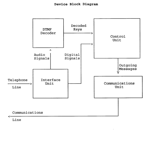
The invention consists of an isolation unit, a DTMF (Dual Tone Multiple Frequency)
decoder, a control unit, and a commllnic~ti~ ns unit.
The isolation unit connects to the telephone line and electrically isolates the rest of the device
from the telephone line. It provides two interfaces to the rest of the device. An analog
interface provides all audio signals that appear on the telephone line to the rest of the system.
A digital interface provides an output that indicates whether the telephone set is on-hook or
off-hook by moni~olillg the telephone line voltage.
The DTMF decoder accepts audio signals from the isolation unit and decodes them to
3 o indicate when a key is pressed and which key is pressed on the telephone set for telephone
sets that generate DTMF tones. The output from the DTMF decoder is a digital signal.
The control unit consists of a microprocessor or microcontroller with associated program
storage. It accepts the digital output from the isolation unit that indicates the voltage level
of the telephone line, and the digital output from the DTMF decoder that indicates that a key
on DTMF tone generating telephone set has been pressed and the identity of the key. Using
this digital information from the isolation unit and the DTMF decoder, the control unit passes
to the colnlllul~ications unit information intli~ting that the telephone h~nflset has been taken
off-hook, that the telephone h~n~lset has been placed on-hook, the pushbutton pressed in the
case of a pushbutton tel~phone, and i~ ;on about the number dialed in the case of a
4 o rotary dial telephone. In the case of a rotary dial telephone set or a pushbutton pulse dial
~11025~
tel~phone set the control unit determines the number dialed by timing how long the telephone
line is at the on-hook and off-hook voltage levels as indicated by the digital output from the
interface unit. The length of time that the telephone line remains at the on-hook and off-hook
voltage levels indicates whether the telephone set is pulse dialing or has been placed on-hook
or off-hook. The number of these pulse dial transitions indicates the number dialed.
The col-llllw~ications unit accepts messages from the control unit and sends these messages
to external devices, converting the digital signals received from the control unit to the voltage
and current levels required to interface with an external device or system.
Figure 1 is a block diagram of the invention which shows the component functions of the
10 system as described above.
The invention, as exemplified by a preferred embodiment, is described with reference to
Figure 2, which is a circuit ~ gr~m of an embodiment of the invention. The diagram layout
in Figure 2 roughly collespollds to the functional block diagram layout in Figure 1.
Referring to Figure 2, the embodiment of the invention shown, the Telephone Activity
Monitor has three external interfaces. Interface Pl connects to the telephone service line.
Interface Jl allows a telephone set to be connected to the telephone line. Interface P2 is a
serial communications output that transmits information to an external device or system.
The interface unit described above and in Figure 1 comprises transformer Tl, opto-isolator
US, and transistor Ql in Figure 2. Transformer Tl provides electrical isolation from the
20 telephone service line for an audio interface to the rest of the device. Transistor Ql and
associated resistors R2, R3, and R4 amplifies this audio signal to provide sufficient voltage
for the DTMF decoder. Opto-isolator US also provides electrical isolation from the telephone
service line while allowing the control unit to detect the state of the telephone line voltage.
Current-limiting resistor R6 provides an ~Jpeld~ing threshold for opto-isolator US such that
the current between the anode and cathode of the light emitting diode in opto-isolator US is
sufficient to allow emitter current in the output of the opto-isolator when a telephone set on
the telephone service line is on-hook, but the current between the anode and cathode of the
light emitting diode in opto-isolator U5 is not sufficient to allow emitter current in the output
of the opto-isolator when a telephone set is off-hook. This current is converted to a voltage
3 0 level by resistor R7 such that a high voltage level appears at the emitter output of the opto-
isolator when the telephone set is on-hook and a low voltage level appears at the emitter
output of the opto-isolator when the telephone set is off-hook.
The DTMF decoder described above and in Figure 1 comprises integrated circuit U4 in
Figure 2. It takes the audio signal from the collector of transistor Ql in the interface unit and
decodes any valid DTMF signal into a 4-bit binary code and a data valid signal. Crystal X2
provides a timebase for the DTMF decoder.
The control unit described above and in Figure 1 comprises microprocessor Ul, latch U2,
and EPROM U3 in Figure 2. Microprocessor Ul accepts a digital voltage level from opto-
isolator U5 into its port Pl.S, which is a high level if the telephone is on-hook and a low
4 0 level if the telephone is off hook. If the telephone on the 1ine i9 a pulse dial type, the di~ital
signal at the microprocessor's port Pl.5 will be pulses corresponding to the dial pulses on
th~ telephone service line. Microprocessor Ul also accepts the decoded DTMF key code
from DTMF decoder U4 on its ports Pl.O, Pl.l, Pl.2, and Pl.3 when the data valid signal
on microprocessor port Pl.4 is at a high logic level.
The microprocessor Ul detects that the telephone has changed from an on-hook state to an
off-hook state by the voltage level on its port Pl.S ch~nging from a logic high voltage level
to a logic low voltage level and rem~ining at the logic low voltage level for a time period
greater than the time period between individual pulses in a pulse dial telephone set. When
this change from on-hook to off-hook state is detected by the microprocessor, the
microprocessor constructs a message indicating this change and sends it from its TXD port
10 to the co~ ni( ~t;on unit, which is shown as U6 in Figure 2.
The microprocessor ~imil~rly detects that the telephone has changed from an off-hook state
to an on-hook state by the voltage level on its port Pl.5 ch~nging from a logic low voltage
level to a logic high voltage level and rem~ining at the logic high voltage level for a time
period greater than the pulse width of individual pulses in a pulse dial telephone set. When
this change is detected by the microprocessor, the microprocessor constructs a message
indicating this change and sends it from its TXD port to the co-l----u-~ication unit.
When the microprocessor has detected that the telephone is in an off-hook state and the
DTMF data valid signal at port Pl.4 is active, the microprocessor reads the decoded key
number at its ports Pl.O, Pl.l, Pl.2, and Pl.3. It then constructs a message indicating the
2 0 number dialed and sends it from its TXD port to the col-ll--ul~ication unit.
When the microprocessor has detected that the telephone is in an off-hook state and the
telephone line voltage as inllic~ted at port Pl.S changes to an on-hook voltage then back to
an off-hook voltage after a period of time less than the maximum pulse width for a rotary
dial telephone set, it then starts to time the period that the telephone line voltage remains at
the off-hook state. If this length of time is less than the m~ximnm period between pulses for
a pulse dial telephone set, it ~ccumnl~tes this number as part of the telephone number dialed.
If it is longer than this maximum time period, the microprocessor takes the accumulated
number of pulses and constructs a message indic~ting the number dialed as the accumulated
number of pulses and sends it from its TXD port to the co...ll.unication unit.
3 0 Figure 3 shows the software flow chart for the microprocessor' s control algolill---- described
above.
The commllnic~tions unit described above and in Figure 1 comprises integrated circuit U6
in Figure 2. This integrated circuit receives the tr~n~mit data from the TXD port of the
microprocessor Ul and converts it to the proper voltage levels and provides the proper
current drive for standard RS-232C commnnications. This RS-232C data is available to
external devices on the P2 interface.
Although only a single embodiment of the present invention has been described and
illustrated, the present invention is not limited to the fealu.es of this embodiment, but
includes all variations and modifications within the scope of the claims.