Note: Descriptions are shown in the official language in which they were submitted.
WO 92/22441
2 1 1 0 5 9 8 Pcr/us92~o48ox
--1 .
~IYBRID INFI-ATOR FOR ~IR BI~
The present application generally relates to a
hybrid inflator which is used to inflate an air bag.
10Inflatable bag restraint systems have been shown to
reduce the seriousness of injuries and number of
fatalities resulting in motor vehicle a~cidents. There
exists a number of means for inflating an air cushion or
air bag such as utilizing a quantity of stored gas which
lS is selectively released to expand the air bag.
Alternatively, a gas source derived from a gas generating
material propellant such as sodium azide, which upon~
ignition thereof generates a sufficient quantity of gas
to expand the air bag. Another type of gas source
~ reDul~ts from a combination of the stored compressed gas
and a~ gas generating or enhancing material. This last
devi~ce is often referred to as an augmented gas or hybrid
inflator. Various hybrid inflators have been shown in
the~ past such as those illustrated in United States
25~ ~ Patents 3,756,621 and 3,895,821. The inflator shown in
Patent 3,756,621 uses a separate squib or initiator to
i~gnite the propellant and an actuator to open an exit
passage to initiate compressed gas flow. Patent
3,895,821 mounted a single squib outside the pressurized
environment of the pressure vessel to ignite the
propellant.
United States Patents 3,891,233 and 3,901,530
illustrate what is called a driver side air bag inflator.
35With reference to United States Patent 3,901,530 there is
..
WO92/22~1 PCT/US92/~8~8
--2--
9~
illustra~ed a hybrid inflator which utilizes an initiator
and a quantity of propellant. This inflator includes a
plurality of burst disks which are opened initially by
the high temperature produced by the burning initiator
and propellant. One disadvantage of this prior art
inflator is that the products of combustion are
transferred diFectly into the air bag. Another
disadvantage is that during the initial inflation of the
air bag very hot gases are produced. As is often the
case, the burn time of a propellent is less than the
total discharge time of the stored gas and as such, the
initial hot inflation gases are followed by the remaining
cooler gas stored in the inflator. In contrast, the
present invention will improve the heat transfer process
between the initiator, pro~ellant and stored gas to yield
a more uniformly heated quantity of inflation gas.
Further, as will be seen from the description below, the
present invention will cause an outlet burst disk to open
primarily due to the overpressurization of the stored
inflation gas. This overpressurization is achieved by
heating the stored gas by products of combustion of the
burning propellant. In this manner, the inflation gases
initially c = icated to the air bag are cooler than
those developed in the prior art, thereby minimizing
damage to the air bag, the air bag cover, and related
mounting hardware. ~hese deficiencies are avoided in the
present invention.
It is an object of the present invention to provide
an improved hybrid inflator. A further object of the
present invention is to provide a hybrid inflator in
which certain products of combustion become ~lated on the
internal walls of a pressure vessel thereby lessening
W092/22~l 2110.~98 PCT/US92/~U8
particulate emission.
Accordingly, the invention comprises: a device for
inflating an air bag comprising: a pressure vessel formed
5 by a vessel part and a generator body assembly. The
generator body assembly is received within opposing
openings in the vessel part (22) and secured thereto ~o
provide a gas tight seal. The generator body assembly
includes: a first bore to receive a ~uantity of
10 propellant and initiator assembly means to cause the m
propellant to burn in response to a control signal
indicative of a vehicle crash. The generat~r body
assembly further includes at least one radial passage
directed toward an internal wall of the pressure vessel
15 such that some of the products of combustion of the
burning propellant will impinge thereon and plate
thereto. A first burst disk is provided to seal the at
least one radial passage and pressure vessel. The first
burst ~disk is opened by the products of combustion
20 permitting same to flow into the pressure vessel and heat
the gas stored therein. The gas generator assembly also
includes a plurality of flow passages communicating with
ehe pressure vessel to an outlet passage, and a outlet
burst disk disposed relative to exit ends of the flow
25 passages and to an outlet passage to pro~ide a gas tight
seal.- The outlet seal is ruptured as a result of
increased gas pressure in the pressure vessel (34)
resuLting from heating due to the burning of the --
propelIant.
.
. 30
Many other objects and purposes of the invention
will be clear from the following detailed description of
the drawings.
W092/22~1 pcT/us92/o48n8
-4-
c;~ O~9~ :
In the drawings:
FIGURE 1 illustrates a cross-sectional ~iew of an
assembled hybrid inflator incorporating the teachings of
the present invention.
FIGURE 2 illustrates a cross-sectional plan view of
a vessel part.
io FIGURE 3 illustrates a partial sectional view of the
hybrid inflator.
FIGURB 4 illustrates a plan view of a plurality of
flow passages formed within the hybrid inflator~
FIGURES 5 and 6 illustrates an isolated view of a
manifold.
FIGURES 7 and 8 illustrate various views of a
diffuser plate.
~: ~ FIGURE 9 illustrates an alternate embodiment of the
invention.
DETAI~ DESCRI PTION OF THE DRAWINGS
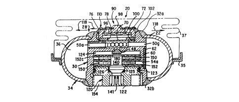
Reference is made to FIGUREs 1-2 which illustrate
various features of a hybrid inflator 20. The inflator
20 can be mounted to the central hub of a steering wheel
in a known manner to protect the driver of a vehicle.
The hyb~id inflator comprises a generally toroidal shaped
vessel part 22 having first and second openings 24 and
26. m ese openings 24 and 26 are generally opposingly
positioned. In addition, the openings 24 and 26 are
tapered outwardly permitting a more effective weld, as
described below. Fitted within the vessel part 22 is a
:~ .
W092/22~1 2 1 1 0 ~ 9 8 PCT/US92/~808
generator body assembly generally shown as 30. The
generator body assembly 30 is joined to the vessel part
22 proximate the first and second openings 24 and 26 to
define a gas tight seal therebetween. The gas tight seal
28 is accomplished by welding the generator body assembly
30 to the vessel part 22 about the openings 24 and 26.
The resulting circumferential welds are shown as 32a and
32b. me generator body assembly 30 and vessel part 22
~ cooperate to define a pressure vessel 34 into which will
be seored a gas generally shown as 36 such as Argon under
a predetermined pressure. Depending upon the size of the
air bag to be inflated, this internal pressure may vary
between 2,000-4,000 psi. The stored gas may also include
a~sma~ quaneity ~2%) of helium used in a leak sensing
process. Positioned about and secured~to the pressure
vessel~is~a bracket 35. This bracket 35 may include
mounting ho1es~noe shown) for atta~chmene to the steering
wheel. A air bag 37 ~is attached to the bracket and
stored~in a~folded orientation prior to its inflation.
20~; A;~cover~(noe~shown) is typically provided to protect the
folded~air bag 37.
Refer-nce is made to FIGURE 3 which illustrates a
cross-seceional view of the inflator 20 and more clearly
25~ shows the~details of the generator body assembly 30. The
generator body~assembly 30 includes a cylindrical walled
body 37 having a first or lower bore 38 and an outlet or
upper~ ore 40. These bores 38 and 40 are generally
` coaxially~ situated relative to the first and second
openings 24 and 26, respectively. Situated at the top of
the ~first bore 38 is a gas inlet passage 42 which is
sealed~by a gas inIet seal 48. The gas inlet seal 48 is
welded in place after the pressurized inflation gas 36
:
: -
WO92/22~1 PCT/US92/~808
--6--
o~9~ :
has been placed within the pressure vessel 34. The
generator bod~ assembly 30 further includes a plurality
of radial passages 50a-g which extend outwardly from the
narrow p~rtion 52 of the stepped ~ore 40. Two such
passages 50a and 50g are shown in cross-section while the
ends of the remaining passages can only be seen in FIGURE
3. In addition, a plurality of pressure passages 54a-c
extend through the cylindrical wall body 37. One such
passage 54a can be seen in FIGURE 3. These ~assages
54a-c communicate to a generator or first burst disk 60
received within and secured to a second bore 62. The
relationship of the second bore 62 to the passages 54a-c
can be seen in FIGURE 4. The second bore 62 is
fabricated on the outward facing side of the generator
body assembly 30 and faces the inside of the pressure
vessel 34. The first burst disk 60 is typically edged
welded to the bore 62.
The hybrid inflator 20 further includes an sutlet or
second burst disk 70 dis~osed and secured to the step
portion 72 of the stepped bore. As can be seen from the
above figures, the step portion 72 is situated between
the narrow diameter portion 52 and a larger diameter
portion 74 defining the stepped bore 40.
Returning to FIGURE 1, a washer 76 is received ~`
within the larger portion 74 of the stepped bore. The
washQ~ 76 includes a central opening 78 having a diameter
that is typically smaller than the diameter of the narrow
portion 52 of the stepped bore 40. As can be seen from
the above figures, the washer 76 rests upon the outer
por~ions of the second burst disk 70 providing a defined
diameter for the rupture disk opening. Also inserted
WO92/22~1 21 1 0 59 8 PCT/US92/~808
within the larger diameter portion 74 of the stepped bore
40 is a manifold generally shown as 90. The manifold
will be welded to adjacent portions of the generator body
assembly 3G. The manifold is also shown in FIGUREs S and
6. The manifold 90 inçludes a central plate 92 and a
downwardly extending circumferential wall 94. The plate
includes a plurality of exit openings 96 and an outwardly
extending boss 98. A manifold screen 100 is positioned
on the underside of the plate 92, the purpose of which is
to filter any b'urst disk material that may be in the
inflation gas prior to communicating same to the air bag.
The manifold screen 100 is also shown in FIGURE 1.
Secured to the manifold 90 is a diffuser 110 shown
in FI~UR~s 7 and 8. The diffuser includes a central
opening 112 which is received over and secured to the
boss, 98. More specifically, it is envisioned that the
material forming the boss 98 will be subsequently formed
to a rivet head construction thereby securing the
diffuser 110 to the manifold 90. me diffuser 110
includes a flexible plate 114 which includes a plurality
of ribs 116 which add a degree of stiffness. With the
diffuser 110 secured in place, the diffuser plate 114
covers~the exit openings 96 formed within the manifold
90. As the stored, pressurized gas exits the manifold
openings 96, the outrush of this gas causes the flexible
plate 114 to move away ~rom the manifold. The diffuser
gene,r~ * y directs the inflation gas to flow radially
outward providing a thrust neutral condition. In this
manner the inflation gases are initially directed away
from the vehicle occupant.
.
Returning to FIGURE 1, the hybrid inflator 20
WO92/22~1 P~T/US92/04808
--8--
further inclu~es an initiator housing assembly 120. The
initiator housing assembly 120 includes a housing 122
received within the first bore 38. The housing 122
includes an initiator receiving bore 126 into which is
received an initiator or squib 140 of known construction.
The initiator 140 upon activation by a control signal
produces an intense flame to cause a quantity of
propellant to begin to burn. The initiator housing 122
is sealed to the generator body assembly and initiator
140 O-rings 123 and 125. As can be seen from the above
drawings, the initiator housing assembly 120 and the gas
generator assembly 30 cooperate to define a propellant
cavity 124 therebetween. Positioned within this cavity
is a quantity of propellant 150 such as Arcite as
disclosed in United States Patent 3,723,205.
In the embodiment of the invention shown in FIGURE
1; a first screen lS2 is placed on the initiator housing
122. Two wafers of typically extruded propellant lS0 and
a,n additional plurality of screens 152b and 152c are also
placed within the propellant cavity. A threaded retainer
154 is used to secure the initiator housing 122 including
the propellant and screens to the generator body assembly
30.
~25 ~ -~
With reference to FIGURE 9, there is shown an
alternate embodiment of the present invention. As can be
; seen,-,~he general construction of the inflator 20 shown
therein is substantially identical to the inflator shown
~30 in FIGURE 1. In the embodiment shown in FIGURE 9, the
; propellant 150 is extruded to take the form of short,
solid cylinders or cylindrical tubes which are placed
uniformly or randomly within a propellant cup 170. The
WO92~22~1 PCT/USg2/~808
-9 - 2 I 1 0 ~ 9 ~
cup includes a plurality of perforations 172. As can be
appreciated, the cup provides a means for retaining the
propellant and the perforations function as flow passagss
to allow reaction products to freely exit the generator
body assembly. An optional screen such as 174 can be
inserted within the cup 170 to enhance ignition of all
surfaces of the propellant. In addition, as can be seen
in FIGURE 9, an additional set of pressure passages 54d-f
are fabricated within the cylindrical walled body 37 and
enclosed by an additional burst disk 60a.
The following is a brief description of the
operation of the present invention. In response to a
~signal indicative of a vehicle crash, a control signal is
communicated to the initiator 140 which is acti~ated.
Upon activation, the initiator 140 produces an intense
flame causing the propellant 150 to begin to burn. As
the propellant burns, the pressure within the propellant
cavity 124 will substantially increase to a le~el that
will cause the burst disk 60a to rupture or open thereby
co:mmunicating the products of combustion into the
~pressure vessel 34. These products of combustion will
inc}ude heat, a small quantity of gas produced by the
~propellant 150, as well as some particulate matter which
`may~incIude molten potassium chloride which is generated
as the propellant 150 burns. Upon opening the ruptured
disk 60a, the~e ~roducts of combustion will forcibly flow
. ~ through~ the pressure passages 54a-c (and 54d-f if
included). As can be appreciated, the hot potassium
chloride as well as other constituents in the heated
gases produced by the burning of the propellant, will
enter the pressure vessel 34 and impinge upon the inside
wall of the vessel part 22. As the pressure ~essel 34 is
WO92/22~1 PCT/US92/~
--10--
substantially cooler than the temperature of the products
of combustion, thè potassium chloride, upon impacting the
vessel part 22, will adnere or plate upon the interior
wall of the pressure vessel 34, thereby diminishing the
quantity of potassium chloride entering the air bag. As
the heated products of combustion enter the pressure
vessel, the temperature of the pressurized Argon gas will
increase rather uniformly. As the temperature of the
Argon gas increases, its pressure will increase to a
level which will rupture the outlet burst disk 70
disposed in the stepped bore 40 thereby permitting the
gases to flow through the exit openings 96 in ~he
manifold 90. The flow of these gases impacts the
diffuser plate 114, lifting same from the manifold.
Thereafter, the inflation gases enter the air bag to
inflate same.
Many changes and modifications in the above
described ~mbodiment of t~e invention can, of course, be
carried out without departin~ from the scope thereof.
Accordingly, that scope is intended to be limited only by
the scope of the appended claims.
: ~ ~'''