Note: Descriptions are shown in the official language in which they were submitted.
~'l/~~92/OQ~r_
_ 192 -10- 0 5
1
DESCRIPTION
A MULTIPURPOSE OPTICAL INTELLIGENT KEY BOARD APPARATUS
TECHNICAL FIELI)
The present invention relates to a key board adapted for
use in appliar..ces such as computers or related terminals,
etc., and more particularly, to a multipurpose optical
intelligent key board apparatus affording the user a variety
of key inputs.
BACKGROUND ART
A general key board is called an "input device" and when
adapted to an electronic appliance, it is arranged to have a
predetermined number of keys, each associated with a
corresponding function. In other words, a key board used in an
appliance such as a computer or related terminal is commonly
supplied with keys bearing English characters . In many foreign
countries, each English character on a specific key is
accompanied by ~~ corresponding character in the mother country
tongue, whereby the two characters different from each other
are printed or moulded in a predetermined arrangement to be
harmonized with the corresponding literary syntax system.
Furthermore, because the literary syntax systems in each of
the European Alphabetic countries have a greater range of
characters and vowel possibilities than the English language,
the key board; in each corresponding country force the
i ~ v~~'a d~sr~
Pcr/l~~e. 92/OQa''
1~9~ -~0- 0 5
~l~.t~~~.~.
2
positions of the keys produced in a new key board pattern.
Typical characters used include those used in the German,
French, Spanish languages.
During the 1980s, various computer software programs
became standardized by using personal computers compatible
with IBM-PCs which utilize "MS-DOS" software. To keep up with
these developments, a computer key board is provided with ten
or twelve keys having different usage purposes from one
another, called "function keys", which are called according to
the software t« be used. These "function keys", along with
"ALT, CTRL, SHIFT and other Keys" are supported by various
command words associated with their combination according to~
the software programming. However, it is inevitable to issue
different command words corresponding to the programming of
each software program because of the characteristics of the
software. Nevertheless, the standardization for the use of
these keys has been impossible till now. Therefore, computer
users are required to study the operating manual and ask the
computer for help by pressing the function key F1 or a HELP
key. Also, it takes a long time to become familiar to the
corresponding program, and the use of new software requires
learning its procedures . Most programming corresponding to the
software to be used is utilized only on the basis of several
command words being well known to the user, and the usage
efficiency of the software is thereby reduced.
One part of most applied software programs divides the
particular portion of a terminal screen, or it supports the
~'T/lr~i ~ 2 / O ~ ~ ~ °:
.., 1~~2 ~i~- G 5
~1~~~~~
3
user facility based on the window concept. However, these
functions occupy part of the memory area independent of the
predetermined memory region for starting the main program to
be used. Therefore, it limits the operation capacity of a
computer and tr.ereby deteriorates the operation efficiency.
Software ouch as "AUTOCAD" is configured to use two
screens, one of which becomes exclusively a command word
space and the other screen forms the working space. This
multi-screen system causes inconveniences, it is non-economic
and inefficieni~ for the user. Touching screens or Liquid
Crystal Touching screens are developed as alternatives for
resolving these problems, but these methods have disadvantages
in respect to the user's degree of acquaintance and errors in
operation caused by careless mistakes.
Considering these points, the main object of the present
invention is to provide a multipurpose optical intelligent key
board apparatus for performing the optical supporting
operation with respect to all programming of software.
Another object of the present invention is to provide a
multipurpose optical intelligent key board apparatus for
supporting any language, in addition to a mother native
tongue, to be used with respect to all keys on a key board.
Also, another object of the present invention is to
provide a multipurpose optical intelligent key board apparatus
for enabling all keys on the key board to represent the
software command words, thereby functioning as a command word
interface.
7 n~ø TT". P"'.'~ Ar' 31~
~~i~~~~ 6 'v.~ i~ =-.. o:ra~aw':
2110801
Another object of the present invention is to provide
a multipurpose optical intelligent key board apparatus for
supporting the software of a key board itself, in which the
arrangement of the key board can be changed to permit all
the keys to show computer command words which correspond to
the software programming to be used.
Still another object of the present invention is to
provide a mu:Ltipurpose optical intelligent key board
apparatus which allows the operation of all keys on the key
board as function keys and the corresponding command word
keys for the control of a particular electronic appliance.
DISCLOSURE OF '.CHE INVENTION
According to the invention there is provided a
multipurpose optical intelligent keyboard apparatus
comprising: a plurality of key tops for displaying a
character pattern according to a software program being
used; a board having a plurality of holes for receiving the
key tops in a predetermined matrix arrangement; a plurality
of light sources for generating light beams along
respective paths below the key tops in the matrix
arrangement; a plurality of light interrupting means
located below 'the respective key tops, an opaque middle
plate located below the board and above the light sources,
having the same configuration of holes as the board;
elastic suppori~ means for elastically supporting the key
tops and the respective light interrupting means on the
middle plate; a plurality of light sensors for sensing the
light beam from the respective light source or for sensing
interruption oi= the light beam by the light interrupting
means; display means located beneath the key tops having an
A
211080 1
optical device in a dot matrix arrangement, for displaying
the character pattern on the key tops, wherein the display
means is capable of changing the character pattern
displayed according to the software program being used, and
5 whereby depression of a key top projects the respective
light interrupting means into the path of the respective
light beam, i~hereby interrupting the light beam and
effecting an operation according to a character displayed
on the key top.
According to the invention, the display means may
optionally in<:lude an illuminating means comprising a
luminescence emitting plate to be operated by a minimum
current at a bottom portion of the display means.
Thus, the present invention enables a controllable
display means capable of changing a given software program
operation to represent a given function key on a
corresponding key top to provide an auxiliary character
arrangement a:~ well as to operate the corresponding
electronic appliance by forcing the light sensing device to
interrupt the function of the corresponding key top when it
is pressed.
This optical key board apparatus is able to represent
all characters used in every language by providing a key
board utility software without the necessity of printing
characters on all of the key tops according to one unique
language.
The optical intelligent key board can also display the
play-role of the function keys used in all applied software
programs on a liquid crystal display (LCD) or light
emitting display (LED) and an optical device below the
bottom portion of each of the key tops. This display state
211080 1
6
is visually recognized through each of the key tops made of
transparent materials, thereby creating a key board which
enhances the u;~er's convenience. As a result, users reduce
their inconveniences of consulting a manual corresponding
to each particular applied software, and the functions of
the applied software maximized to overcome any disadvantage
caused by the user's partial knowledge.
The present invention furthermore can provide a
multipurpose intelligent key board apparatus compatible
with any software programming. The multipurpose intelligent
key board apparatus can be adapted to a note-book PC and
Lap-top computer, so that it may be used like an exclusive
use terminal of: a word-processor, a data base computer and
a spread sheet. It cannot only be adapted to the key board
of a Position of System (POS) terminal and a portable
telephone, but also to achieve various additional functions
as well as the reduction of the number of key switches on
the key board.
BRIEF DESCRIPT7:ON OF THE DRAWINGS
The present invention will now be explained in detail
with respect to the attached drawings, in which:
Fig. 1 is a plan view showing the arrangement of a
conventional ~~ey board corresponding to an AT type
computer;
Fig. 2 i:~ a view illustrating the arrangement of
optical couplers adapted to the principle of the present
invention;
Fig. 3 is a view illustrating the adaption of the
switching functions of the key tops to a dot matrix
according to tr.e principle of the present invention;
211080 1
Fig. 4 i~; a schematic view illustrating the display
state of the function key tops according to the principle
of the present invention;
Fig 5 is an exploded perspective view illustrating
important components when the present invention is adapted
to an AT type lcey board;
Figs. 6A and 6B are cross-sectional views illustrating
the assembly of the present invention, in which Fig. 6A
illustrates th~~ state of the key tops when fitted into a
light interrupi~ing device;
Fig. 7 and Fig 8 are plan views illustrating the
arrangement of a key board adapted to the English/Korean
language word-processor according to the present invention;
and,
Fig. 9 and Fig. 10 are exploded perspective views
illustrating t:he control key board of an electronic
appliance according to the present invention.
BEST MODE FOR CARRYING OUT THE PREFERRED EMBODIMENTS
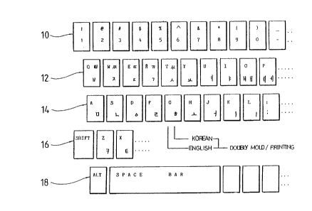
Fig. 1 shows parts of a conventional AT type key board
adapted to the IBM PC, which includes an arrangement of
both Korean and English characters. The key board is
provided with a plurality of key top groups 10, 12, 14, 16,
18... each arranged by line, each group consisting of key
tops on which corresponding characters are printed. For
example, the key top group 10 in the first line is arranged
so that the key tops respectively represent numbers 1, 2...
and the predetermined alternate characters !, @... which
are selected by using the SHIFT key. The key top group 12
has key tops in one line which represent the English
capital letters Q, W, E... and alternate Korean characters
A
2110801
8
which are selected by using the SHIFT key and the English
characters q, w,... and alternate Korean characters which
are selected w~''_thout the SHIFT key. The ALT key of the key
top group 18 performs a special function when used in
combination with one of the other key tops.
These key top switches on the conventional key board
have upper :>urfaces printed with the predetermined
corresponding <:haracters or are doubly moulded to have the
predetermined corresponding characters. The configuration
of the key top switches may be variously adapted to the
mechanical contact type, the electrostatic capacity change
type or the membrane type, etc.. However, even if only one
of the key top switches becomes out of order, the key board
can only be repaired by being totally disassembled.
In light of these points, the present invention
includes a plurality of key tops configured in a
rectangular matrix or other predetermined shape and made of
transparent materials, such as glass, acryl resin, epoxy
resin, plastic or crystal. These materials are able to
transmit the light by optical refraction to create visible
characters, graphs and figures represented in a display
device such as an LCD screen which is positioned below the
key board bottom surface, thereby creating the same effect
as those on the printed key board. Thus, an optical
transmitting key board is constructed in order for its key
tops of transparent materials to visually display
characters, gr~~phs and figures represented by a display
device in either the original proportion or in a reduced or
enlarged proportion by means of the optical refraction
method.
__ 2~~oso~
9
First, the' key tops are respectively coated or covered
on their vertical lower side surfaces by opaque materials,
so that they are positioned on the horizonal plane X and Y
coordinates like a matrix arrangement of more than 6*32
consisting of infrared ray receiving and emitting elements,
thereby detecting the light blocking positions. The light
source may optionally comprise an optical beam or laser.
The transparent: key tops also are coated on their vertical
surface by opac.ue materials, so that an optical wave guider
of transparent materials is positioned therebetween to
guide infrared rays, thereby detecting the displacement of
the key stroke to cause a sensing device to read the scan
code on the X and Y coordinates.
According to the principle of the present invention,
the key top switches are arranged as shown in Fig. 2, in
which the vertical columns and horizontal rows form a
matrix. A computer keyboard is similarly arranged in 6
columns * 32 rows of a minimized unit. The key matrix has
a light emitting diode group 21 positioned in the right
columns of the: drawing and a photo-transistor group 22
consisting of light receiving elements located in the left
columns along t:he same line as the light emitting diodes.
Also, a photo-transistor group 23 is arranged in the upper
rows and a light emitting diode group 24 in the lower rows
corresponding to the light receiving elements. These
arrangements for a switching matrix of columns V1 to V6 and
form rows H1 to H5 as shown in Fig. 3. It is based on the
concept as illustrated in Fig. 4.
Assuming that function key tops F1 to F12 are
associated with an AT type key board which is adapted to
the software of a predetermined word-processor, the key top
2110801
F1 or 31 is a key top HELP, the key top F2 or 32 is a key
top ASSIST, the key top F3 or 33 is a key top APPEND, and
the key top F4 or 34 is a key top BROWSE; each are made of
transparent materials to represent a predetermined
5 corresponding j=unction. Below the bottom surface of these
key tops a li~~ht emitting element group 21 and a phot-
transistor group 22 receiving infrared rays are mounted in
a matrix arrangement. The optical coupler groups 21 and 22
are provided with function key tops 31 to 35 which function
10 as optical switches, on each of which opaque material or
light interrupting devices 41 to 44, which may be metal,
are mounted in the same line with the photo-coupler groups.
An LCD type di:oplay device 112 is mounted below the bottom
surface of light interrupting devices 41 to 44 to enable
the function key tops 31 to 35 to represent the
corresponding :_nformation as described in detail below.
A typical example of the present invention adapted to
a computer key board is illustrated in Figs. 5, 6, 7 and 8.
A typical example of the present invention adapted to a
telephone key board or calculator key board of an
electronic app7_iance is illustrated 'in Figs. 9 and 10.
Referring to Fig. 5, a multipurpose optical
intelligent ke~T board apparatus 100 comprises a key board
front plate 102 having a plurality of holes 101 for
receiving corresponding key tops, respectively, which are
arranged in a predetermined matrix. The key tops 104 are
made of transparent materials, such as acryl resin, epoxy
resin, plastic, glass or crystal, in the form of a
rectangular shape as shown in the drawing or another
geometrical sh<~pe. The key top 104 is fitted into an
optical interrupting device 105 constructed to wrap around
A
2t loco ~ ~~
11
its periphery at a predetermined height. The optical
interrupting cLevice 105 is made of metal or any other
material capab:Le of interrupting light.
The optical interrupting device 105 is provided with
a flange 107 :horizontally extended at the predetermined
height from each surface of the key top 104. The
predetermined height is set to allow the flange 107 to be
elastically sug>ported on the lower surface of the key board
front plate 102. and to be contacted with a middle plate 108
when the key top 104 is pressed.
A leaf spring or coil spring 106 is supported on the
middle plate 108 having relatively small holes 109 formed
in the same arrangement as that of holes 101 and 103... on
the key board front plate 102 in order to elastically
retain the ke~~ tops 104 with the optical interrupting
device 105. A plurality of optical guiders 110 are mounted
adjacent to the bottom surface of the middle plate 108,
which has a plurality of optical couplers around the
periphery of th.e key board 102. The optical guider 110 is
configured to have the same arrangement as that of the
holes 101 of the key board 102, in such a manner that the
photo-coupler groups, including the light emitting diode
and photo-transistor, are disposed on the front and rear
portions and the left and right portions of the key board.
The drawing illustrates three light emitting diodes of the
lower light emitting diode group 24 and one light emitting
diode of the left emitting diode group 21. In addition,
the optical guiders 110 are configured to receive all
optical interrupting devices 105 related with a plurality
of key tops 104, respectively. A flat LCD type display
device 112 is located below the bottom surface of the
211080 1
12
optical guider 110 so that it can be divided to conform to
the arrangement of the holes 101 on the key board 102 to
display the character or function of the key tops 104.
The liquid crystal display device 112 may be a dot
matrix liquid crystal plate which displays information of
the function key tops and the character key top according
to the software programming. The liquid crystal display
device 112 may have a luminescence plate 113 on its lower
portion to meet the user's needs with respect to the
background color.
All these: components may be assembled into a base
plate 114, and then the base plate 114 is coupled with the
key board 102 t:o complete the assembly of the multipurpose
optical intelligent key board apparatus 100.
Specifica=Lly, as shown in Figs. 6A and 6B, a key top
104 is projected upward through a key board 102 while being
supported by a leaf spring 106 between a middle plate 108
and a flange 107. An optical guider 110 is fixed to the
lower surface of the middle plate 108. A display device
112, a luminescence plate 113 and a base plate 114 are
arranged in order below and spaced from the bottom surface
of the optical guider 110.
The multipurpose optical intelligent key board
apparatus 100 can display information of the
function/charac:ter key tops according to the software
program to be used as illustrated in Figs. 7 and 8.
Referring to Fig. 7, the functions of key tops 31, 32, 33,
34... illustrate its corresponding function in Korean
characters, thc~ number key top group 10 represents only
numbers, the character key top groups 12 and 14 show the
key functions corresponding to Korean characters and the
X110801
13
key tops SHIFT and ALT of the other character key top
groups 16 and 18 permit the corresponding functions to be
visually perceived. The Korean display key tops may be
represented in English as shown in Fig. 8. The explanation
with respect to Fig. 8 is omitted because it is the same as
the explanation for Fig. 7.
Figs. 9 and 10 illustrate examples adapted to an
electronic appliance, in which Fig. 9 is an exploded view
of a calculator, and Fig. 10 is an exploded perspective
view of a key :ooard adapted to an electronic appliance.
The important components shown in Figs. 9 and 10 are
the same as those of Fig. 5, for which the same components
are referenced as the same numbers, and their detailed
explanation is omitted. The differences between Fig. 5 and
Fig. 9 consist of the photo-transistor group 22 which
includes a plurality of light receiving elements arranged
against a light emitting diode group 21 including a
plurality of l:~ght emitting elements, and a liquid crystal
display device' 112 displays characters associated with
information ~~orresponding to the key tops. The
configuration of Fig. 10 is the same as that of Fig. 9,
except that a leaf spring for elastically supporting key
tops 104 is su~~stituted with a coil spring 106.
INDUSTRIAL APPLICABILITY
As described above, the present invention strengthens
the support of a software program with respect to a liquid
crystal displa~r device for displaying not only the command
words of the software but also the characters to be used,
in which the key board connected to a computer is supplied
with information about the function keys and character
2l~oso~ T
14
keys. Thus, the present invention can assist in the
operation of the programming associated with a computer or
an electronic appliance by providing users with a plurality
of optical representing key tops.