Note: Descriptions are shown in the official language in which they were submitted.
:
This invention concerns a sweeping unit, in particular as a
supplementary equipment for a scrubbing suction-action machine,
with at least ona driven sweeping device provided on a guide,
while the guide consists of several elements, some parts of ;
which are arranged fixed, other parts displaceably for the
purpose of altering the sweeping width of the sweeping unit. ; ;
Such a sweeping unit is Xnown from FR 2 652 lOO Al. It has two
sweeping devices, each of them comprising a bristle-studded ~;
belt, which runs about two rollers with vertical axes of
rotation, which rollers form the respective guide. One of the
rollers is provided fixed, the other pivotably. To narrow the
working width, in the case of the known unit both displaceable
rollers of the sweeping devices are aligned in the working
direction, i.e. pivoted forward and inward.
A ~urther sweeping unit, known from DD 269 549, has a
transversely running brush belt which is guided about rollers
having horizontal axes on both sides of a centrally situated
suction orifice. The two brush belts can be pivoted in a
horizontal plane into an open to the front V-shaped position,
so that the sweeping unit could travel through narrow
25~ positions. The guide elements o~ the two brush belts, as far as -
a belt guidance is concerned, are not displaceable.
An automatic defleckion when encountering an obstacle is not
possible in the case of either known sweeping unit. Rather, the
V-position of both brush belts~has to be set accordingly before
entering into an obstacle, to prevent the outer ends o~ the
brush belts bumping into the limits forming the obskacle~
The known sweeping unit~ are not envisaged to be used as ;~
supplementary devices ~or a scrubbing suction-action machine.
" ;,
In contrast to this, the object of this present invention is to
produce a sweeping unit which makes an inside and outside
, - ~
~.L L f)(;~
mechanical sweeping with varlable working width ~easible r g~
that an automatic a~justment o~ it5 contour can he c~rried out.
Appropriately, the sweeping unit should be able to be used with
any scrubbing suction-action machine. A particular objective o~
this invention is also to use the sweeping unit in conjunction
with a scrubbing suction-action machine having a variable
working width, which is the subject matter of the German patent
P 41 03 087. The working width of the sweeping unit should also
be variable similarly to the working width o~ the scrubbing
suction-action machine.
At the same time the cleaning of very dirty floors and/or of ~
such which have increased demands on them as ~ar as cleanliness ;
is concerned, should also be able to be carried out
economically. The cleaning of such ~loors is carried out
currently in such a manner that first the dirt lying loosely on
the floor is swept away, usually by hand, and afterwards the ~ .;
dirt stuck to the floor is cleaned by means of a scrubbing
suction-action machine. In numerous applications, e.g~ when
cleaning floors of supermarkets or departmental stores, the
sweeping preceding the scrubbing i5 unavoidable. Hard dirt,
e.g. glass splinters, would be picked up otherwise by the
rotating scrubbing brushes and this would lead to the damaging
of the floor, or it could damage the soft rubber stripper rail
of the scrubbing unit; furthermore, paper in particular, e.g.
thrown away cash register dockets would adhere to the Ploor ~ ~-
which had been wetted by the scrubbing process. Thus the two
working processes ~sweeping and scrubbing) which are ~requently
required when aleanlng floors;and which have to; be carried out
in succession, will con~equently result in high costs.
According to the invention the objective mentioned is achieved
with a ~ensric sweeping unit by that the displaceable guide
elements with the decrease of the sweeping width can pivot or
move inwards in the direction opposed to the working direction ~ - -
relative to the fixed guide elements assigned to the relevant
sweeping device. In this application und2r the te~m "guide" o~ ~
2 ;
~:' '
% :I. L () ~ l. .l
the sweepiny device the totality oP individual elements is to ;~
be understood, which serve the purpose of guidancs and width
adjustment of the sweeping device; in particular reversing
rollers, pressure rollers, guide rollers, sliding surfaces,
guide rails and the like may be considered as guide elements.
The sweeping device may comprise hand driven or motorised
brooms of designs known in the field of cleaning machines, e.g.
plate brooms rotating about vertical axes or roller brooms
rotating about horizontal axes or bristle-studded endless
sweeping belts.
If endless sweeping belts are used, ik is useful if at least
two endless sweeping belts (1) are provide~ which rotate in an
upright configuration about the guide elements.
The displacement of the guide within the sweeping unit may take
place by various means; those elements, for example, which can
be displaced, may be made pivotable, so that they would include
a varying angle with the working direction; furthermore, in ~;~
case that several guides are provided with sweeping belts, they ~-
-
may be mounted laterally displaceably on the sweeping unit; ~ ~ -
finally, a displacement is feasible by that it is constructed
inherently deformably, i.e. the position of the individual
; ,. . . .
elements of the guide can be altered relative to each other, so ;
that the path of the rotating sweeping belt may take up
different shapes (straight, curved inward/outward or
forwa~d/rearward). For this purpose the components connecting
the elements of the guide may consist, for example, o~ a
flexible material or may be constructed of members which are
joined with each other in an articulated manner. The ! ' ',
construction of the broom as a continuous sweeping belt is
especially advantageous when a de~ormable guide is provided; in ;
this manner with the adjustment of the position of the guide
that of the broom can also be adjusted in a simple manner to ~-~
suit the respective desired working width. Furthermore, the~' ;
construction of the broom as a sweeping belt has the particular ~ ~;
advantage, that the picked up dirt (more directly than in the ~ ;
case of roller brooms /sweeping rollers/ and plate brooms) are
: :'
sl '
~l .L ~)81 t
conveyed to a narrowly limited region, namely to the reversing
point of the sweeping belt; consequently, the suction can be
limited to this narrowly restricted region, i.e. the suction
orifice can be dimensioned correspondingly small, leading to a
5 small throughput rate of the exhausted air and, in turn, to a ~ '
small power requirement of the exhaust unit. This has
particular significance in conjunction with that khe sweeping
unit according to the invention should also be able to be
operated in combination with a scrubbing suction-action machine
10 which is independent from the mains and have a correspondingly
limited battery capacity.
,.:, ,
The sweeping unit according to the invention has preferably at
least two endless sweeping belts with associated guides, which
15 sweeping belts run about the guide elements in an upright
configuration. At the same time at least one pair of sweeping
~; belts is preferred, wherein the sweeping belts are driven in
~;~ opposing directions to each other and convey the dirt to a
I suction orifice of a suction device which picks up the swept-up
20 material and which is provided between the two sweeping belts
of the pair. Accordingly, the reversing points of both sweeping
belts of the pair are arranged close to each other and in the
vicinity of the common suction orifice. It is conceivable in -
this case, that two further sweeping belts could be connected
' ~ 25~ in a staggered manner behind the pair of sweeping belts
mentioned, while the two front sweeping belts are suspended
fixed on the eweeping u~it and the sweeping belts connected
behind them can be laterally moved and/or pivoted; this permlts
a rigid construction of each individual guide, i.e. in
~ 30 particular to mountla~llelements of a guide on a com~on rigid
;~ carrier, which are suspended inside of the sweeping unit either
rigidly or displaceably. Conversely, the guides, as such, may ; ;
be deformable, i.e. the individual elements of the guide can ;~
change their position relative to each other. This will change
the contour of the sweeping belt, rotating around the guide
elements. The carrier, connecting the guide elements with each
other, comprises appropriately in this case several sections,
which are joined articulately with each other.
: .~
4 ' ~
; , , ... - , - ,." - ,, ~ ,, ,, . ., .. ::: , . . .
~, :1 L (3 '~3 ~
In the case thak several guides with rotating sweeping belts
are provided, they can be displaced preferably independently
from each other. This will permit a single-sided alteration of
the working width, when, for example, an obstruction occurs on
one side only. This will increase the flexibility of the
selection of the optimum working width compared with
corresponding sweeping belt guides, which are displaceable only
symmetrically in pairs.
In the case of a preferred development of the sweeping unit a
suction ori~ice is provided at each reversing point of the
sweeping belt. It is because not only the front section, viewed
in the working direction, of the sweeping belt picks up dirt,
but the rear section also conveys a certain amount of dirt to ~ --
the relevant reversing point, as a lO0~ sweeping efficiency
cannot be technically achieved by khe front section of the ~
sweeping belt. Appropriately, in the region of each suction s
orifice a stripper hook is provided, the bristles of the
sweeping belts brushing against it. The ef~ect is that the dirt
will be loosened better from the bristles and can be picked up
by suction orifices of the suction device O At the same time the
sweeping efficiency can be increased by that the bristles of
the sweeping belts are inclined against the direction of
rotation, i.e. the bristles point forward at an angle in the
direction of rotation o~ the sweeping belts.
When using sweeping belts it could be advantageous for picking
up rough dirt, if in the region of the suction orifices and/or
directly along the rear side o~ the sweeping belt a stripper is
provided. In this case one deals usefully with a conventional
belt-shaped elastic bar which glides over the floor surface,
the lengkh of which can be extended together with the sweeping
belt.
, .,
Appropriately, when vièwed in the working direction, a
deflector bracket is provided in front of the sweeping belts,
which bracket, when encountering an obstruction, affects the
displacement of the carrier so that the sweeping width will be
reduced. For this purpose various technical ~olutlons are
conceivable. For example, the de~lector bracket may be
constructed as a scanner, which, in turn, controls an electric,
pneumatic, hydraulic or similar adjusting device to pivot
and/or move the corresponding sweeping belt guide assigned to
it. On the other hand, especially in the case of small sweeping
units, the deflector bracket can be constructed so, that it
moves and/or pivots directly the sweeping belt guide assigned ;~
to it when it encounters an obstruction, i.e. the corresponding ;
guide is moved and/or pivoted dire~tly by the obstruction
affecting the dePlector bracket until the sweeping unit is
capable to pass the obstruction.
To keep the stirring up of the dust at as lo~ a level as ~i
possible, the sweeping unit can have an additional misting
system. In this case the to-be-vaporised ~luld is r~moved by
suction from a storage tank by means of a pump and sprayed
about through pressure hoses, which are fastened along the
sweeping belts and have a plurality of vaporising nozzles.
The sweeping unit according to the invention can be mounted on
a chassis thus forming an independent sweeping suction-action
machine. In an advantageous manner it is also feasible to
construct a scrubbing suction-action unit with variable working
width according to the German patent P 4l 03 087 and mount a
sweeping unit according to the invention on a common chassis,
so that a ccmbined sweeping and scrubbing suction-action
machine will be produced. In this case the working width of the
sweeping unit and of the scrubbing suction-action unit are co-
ordinated with each other,!i.e.!the displaceable parts are
joined with each other. A development oP the sweeping unit
according to the invention is particularly useful in a manner
wherein the mounting means ~or a rapid assembly on a scrubbing ;
suction-action ~ch;nq are according to the German patent P 4l
03 087. The ~astening means used for the rapid assembly of the
sweeping unit to the scrubbing suction-action machine are known
as such ~rom the state-o~-the-art.
~1 L()~
The invention with a sweepiny deviae in the ~orm oP a
continuous endless sweeping ~elt is ~xplained in detail below
based on the drawing. Shown is in:
Fig.l - a top view of a sweeping ~nit according to the
invention when mounted on a scrubbing suction-action
-ch; ne;
Fig.2 - a section across the combined sweeping and scrubbing
suction-action machine according to Fig.l, along line ~- -
,:,
Fig.3 - a section across the combined sweeping and scrubbing~ ;~
suction-action machine according to Fig.l, along line
III-III;
Fig.4 - a schematic top view of a version of the sweeping
machine.
,, , ~ , ~.
~ Since it is not a subject of this application, the scrubbing
suction-action machine is illustrated by thin lines, while, in ~,~
contrast, the sweeping unit according to the invention is ~'
illustrated by thick lines. The sweeping unit illustrated in ~-~
the drawing contains two endIess sweeping belts l, which are
;~25 fitted at their bottom edges with bristles 2. At the same time
the swesping belts are made o~ a flexible, skretch-resistant~ -
belt materlal or of articulated elements which are connected ~
with each other in a chain-like manner. Both sweeping belts run ~ ;
between a drive roller 3 and a reversing roller 4, which define
both turning points.~A hori~antal drive motor 5 is provided~for
each o~ the two sweeping belts, which motor is connected with ~ ~
the respective drive roller 3 via a bevel gear transmission. i~-
Two additional guide rollers 7 as well as guide sur~aces 8 are
provided to guide the aweéping belt.
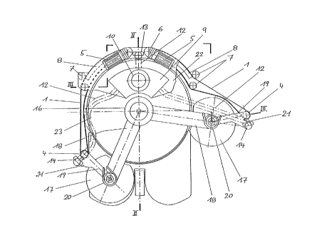
The suction unit comprise~ the suction reservoir 9, on which
the suction motor lO is mounted, which drives the exhaust fan
(not illustrated). A ~ilter is installed on the suction
~ 1 L O ~
. . .
reservoir as a separator devlce 11, which ~ilter ~eparate~ the
dirt picked up by the sucked in air from it and retains it in
the suction reservoir. Three suction hoses 12 snter into the
suction reservoir 9, which suction hoses are connected with a
front, central suction orifice 13 and an external, rear suction
ori~ice 14 each. (Not to conceal the parts lying below, the
suction hoses 12 in Fig.1 are indicated by dash-dot lines
only). At the same time the front, central suction orifice 13 ~;
is provided between the two front ends of the sweeping belts
where they rotate around the drive rollers 3. The rear suction ~ -
orifices 14 are provided directly behind the reversing points
o~ the sweeping belts, which are defined by the reversing
rollers 4. The suction motor is supplied by a current source
(not illustrated).
The sweeping unit illustrated in Figs.1-3 is mounted on a ;
scrubbing suction-action machine known from the German patent
P 41 03 087, the outline of which is indicated by thin lines
and the details o~ which are apparent from the above mentioned ~ -
~patent] application. Important is that in addition to the main ~ ~;
brush 15, which is driven by the drive motor 16, displaceable ~ -
supplementary brushes 17 are provided, which supplementary ,brushes can pivot laterally by means of a swinging arm 18 each.
In accordance with Fig.1, when viewed in the working direction,
the left supplementary brush is in its retracted position, the
right supplementary brush in its extended position. For the
interaction o~ the sweeping unit and the scrubbing suction- '
action machine in such a manner that the working widths of the
two units would be harmonised with each other, tensioning
levers l9 are hingedfonlthei~swinging arms 18 o~ the scrubbing
suction-action unit, each o~ which carries a reversing roller
4. At the same time the tensioning levers 19 can pivot about a
vertical axis relative to the swinging arm 18. A spring 20,
arranged between each swinging arm 18 and the associated
tensioning lever 19, pre-tensions the tensioning lever to such
an extent, that the sweeping belt 1 will be tightened to its
optimum. On each tensioning lever 19 a brace 21 is provided,
:
~ '
~1 11)311
which serves the purpose of holding the respective exkernal,
rear suction orifice 14.
The drive motors 5, guide rollers 7 and guide surfaces 8 of
each sweeping belt 1, as well as the suction reservoir 9 and
the front suction orifice 13 are mounted on a common mounting
platform 22, which is secured on the hood 23 of the main brush
15 of the scrubbing suction-action unit. To enable to
illustrate the parts of the guide arranged below the mounting
platform, in Fig.1 the mounting platform is shown broken on the
right-hand side of the sweeping unit.
"~,
The sweeping device of the sweeping unit can be driven by a
motor or by hand. If it is hand driven, a transmission unit may
be used for this purpose, which is coupled in the usual manner
with the wheels of the pushed sweeping unit. In addition, a
battery for the electric motor drive of the exhaust fan of the
suction unit may be provided. Also, instead of a suction unit
another storage device for the swept up material may be used, -~
like, for example, a bristle-studded pick-up roller, which
conveys the swept up material rearwards, pre~erably over a ramp
which ends near to the ground or grazes the surface o~ the
~ ground, into a swept-up material container joined to it. Such a
; version is illustrated in Fig.4.
Fig.4 shows a top view of the front half of a sweeping machine
whose sweeping unit does not have a suction unit. Instead o~
that it has a sweeping roller 25, which rotates about a
~ horizontal axis 26, which is situated at right angle to the
; 30 longitudinal axis 27~oflthe's~eeping machine. ~he sweeping
roller 25 conveys the swept-up material which has been picked
up between the front ends o~ the two sweeping belts 1 upwards
from below over a stripper rail 29, the leading edge 28 o~ the ;;
stripper rail being on the ground and then rising in a ramp-
i 35 like fashion to a swept-up material container 30 connected to
it. Of the two sweeping belts 1 the top one in the plane of the
drawing is illustrated in extended position, the bottom one in
inward pivoted position. While the three front guide rollers
~g ' ~'.
:
31, viewed in the direction o~ tra~el F, are mounted on the
machine, the rear reversing roller 32 can be pivoted according
to the double arrow P, due to which the variable sweeping width i
o~ the sweeping machine can be realised. On the example o~ the
above shown sweeping belt a stripper 33 is also indicated in
broken line, which moves in unison with the pivotable rear .;:-
section o~ the sweeping belt.
., ~
: ': " '
':-~''"".'.'
""'''''
' ~ .',:, ''",',
~ ,',,,
:~ :
~ ' ~ ' '"
' ' ' ' ' '
~ ' '''''';
.' .:
~ ' - '.'~