Note: Descriptions are shown in the official language in which they were submitted.
1~0 92/21445 PC'TIL~S91/07~06
~N~LATA~L~ o~o~ ~ ~~o~~~~~ o~~~~z~u~~
Field of the-~~~rention
The present invention relates to a decanter
centrifuge. Tn particular, the present invention relates
to the control of the pond level within a decanter
centrifuge so as to vary the characteristics of the
separated solids discharge and the liquid centrate. This
control of the discharge char~ct~rist~cs is made during
the operation of the centrifuge.
1~ ~aokc~round of the Ixavemt~.on
The depth of the pond in a decanter centrifuge
is particularly relevant to its successful operation.
This fact is particularly true when the centrifuge is
operating in an "above spillover°° condition. An above
spillover condition occurs when the pond surface in the
bowl of the centrifuge is radially inward of the solids
weir surface.
The operational characteristics of a decanter
centrifuge in an above spillover condition are described
20' an various forms in Ambler U.S: Pat. No. 3,17~,8~1 and
Lee U.S~.~° Pat. No. 3, 7~5, X61. In the Ambler device, a
solids dam must form at the solids discharge weir in
order for the liquid layer to provide its contemplated
hydraulic assistance to the solids discharge. In the Lee
2~ construction, the baffle projecting from the conveyor hub
must penetrate and seal with the solids layer within the
WO 92/21445 c~, PCT/IJS91/07306
~i
centrifuge bowl to create a centrifugal pressure head
assist to the conveyor in the discharge of the separated
solids. The relative difference in radius between the
solids and liquid weir surfaces can be used to create the
above spillover condition and be used to control the
operation and performance of a decanter centrifuge.
However, precise control over the parameters of the above
spillover operation is often required.
During start up of a decanter centrifuge
to operating in an above spillover condition, a solids layer
must be built up within the bowl in order for the centri
fuge to reach a steady state operation. In both the
ambler and Lee type operation, because the solids weir is
typically radially outward of the liquid weir, the liquid
feed mixture will discharge over the solids weir during
start up prior to reaching steady state operation. This
condition will also occur during a °'wash-out'°, until the
dam or seal are again formed. The: reformation of the dam
or seal to again achieve a steady state operation may
require significawt operator attention and result in
substantial loss of operation time for the centrifuge.
Liquid discharge through the solids discharge ports is
normally considered unacceptable.
LaMontagne U.S. pat. No. 4,575,370 shows a
liquid discharge weir for a decanter centrifuge that
operates under different conditions based upon the feed
rats into the centrifuge. In LaMontagne, the weir plates
for the liquid discharge include a notch or the like
which interrupts the weir surface. At low flow rates,
the liq~.aid is discharged through the notch which is at a
pos~.tio~i~~~radially outward of the solids discharge weir.
At higher flow rates, such as that of normal operation,
the flow over the liquid discharge weir is great enough
to raise the level of the pond within the bowl radially
inward of the solids discharge weir, i.e., to an above
spillover condition. Thus, LaMontagne contemplates that
W~ 92/21445 Pf_°f/US91/07306
-3-~.~. ~~J~,
the flow rate may be used to control the operational
characteristics of start up and prevent liquid discharge
through the solids discharge parts.
The Lee decanter centrifuge creates a centri
fugal pressure head which directs the solids through the
annular passageway defined by the baffle periphery and
the bowl wall to assist in the discharge of the solids.
It has been found that this pressure head substantially
improves the operation of a decanter centrifuge in par
ocular with respect to a thickening type operation. The
.: Lee:. type centrifuge has- also been found applicable to
what is known as.''difficult-to-convey"= type solids.
These difficult-to-convey solids are normally not dis
chargeable from a decanter centrifuge by the screw con
veyor alone and often require the use of polymers or the
like to create acceptable separation.
In certain situations in the operation of a Lee
type decanter centrifuge, the concentration of the solids
discharge is difficult to control. In waste water
2p thickening, the production of a cake having up to a ~
solids concentration is possible typically on a consis-
tent basis. Also, the production of a solids concentra-
tion in excess of 8% is consistently possible. However,
in the range between 4o and 80, it is often difficult to
produce a consistent cake concentration. The reason for
this difficulty is attributed to the inability to precis-
ely control the pond level and to adjust for changes in
feed rate and feed solids concentration.
Operation of a Lee type decanter centrifuge in
3~, an above spillover condition has been found to be most
advantageous in waste water thickening. However, similar
advantages have been found for an above spillover condi
tion in the concentration of solids in a dewatering-type
operation, in which the solids concentration is usually
greater than 20%.
wo ~ziz~aas ;, Pcriu~~mo~~os
t.
;~ / t ~,.~
lu_ t ,.
It is known to use an inflatable type dam
within a centrifuge for creating a liquid-liquid separa-
tion.. Such an inflatable dam is shown in Sharpies U.S.
Pat. No. 3,179,34. However, a liquid-liquid type sepa-
ration includes different operational characteristics and
parameters from those in a liquid-solids type separation
of a decanter centrifuge. In the operation of a decanter
type centrifuge, the depth of the pond within the centri-
fuge is often critical to successful operation and in
controlling the characteristics of the separated solids
discharge and the liquid centrate. Variation in the
depth of the pond in a liquid-liquid separatiow is useful
in locating the liquid-liquid interface to control liquid
clarity.
The relative change in operation of a centri-
fuge used for a liquid-liquid type separation as compared
to that of a decanter centrifuge used for a liquid solids
type separation as a function of the radial difference
between the weir surfaces of the separate discharges
displays the differences in operational characteristics
and the different parameters of operation of the two
types of centrifuges. The following is an outline of
same of these differences, making reference to a Lee type
decanter centrifuge.
One operational characteristic of a centrifuge
is the location in the centrifuge bowl of the interface
a
between the lighter density material (typically a liquid)
and the heavier density material (either a liquid or a
solids type material). In a liquid-liquid type separa-
30, Lion, the interface is considered to be relatively sharp
and welZ~~-~defined. However, in a decanter type centrifuge
this sharp definition is not necessarily found. The
location of the interface in a liquid-liquid centrifuge
is the function of the density ratio of the two liquids
being separated and the relative distance from the axis
of rotation of the weir surfaces for the two materials
WO X2/21445 1'CT/US91107306
~~~~~%~
being discharged. The location of the interface in a
Lee-type decanter centrifuge is a function of the density
difference between the liquid and solids {with the solids
concentration varying at different radial positions in
the bowl), the relative radial difference between the
weir surfaces, the rate of the feed into the bowl, the
solids concentration in the feed, the differential speed
of the screw conveyor with respect to the bowl, the speed
of rotation of the bowl, and the compactability of the
solids material.
A change in the feed rate in a decanter
centrifuge will result in a change in the location of
this interface and 'the discharge characteristics of the
solids. An increase in the feed rate will typically
result in the interface moving radially inward. Feed
rate changes in a liquid-liquid type separation do not
result in substantial changes in the discharge charac-
teristics or a movement of the interface.
Ndoving the light liquid discharge weir surface
radially inward in a liquid-liquid separation {i.e. rais
ing the pond surface with respects to the heavy liquid
discharge weir) will result in the interface moving
radially outward. However, the flow rate of both the
light and heavy liquids are not affected by the change in
weir location. If the liquid discharge weir surface is
moved radially inward in a Lee-type decanter centrifuge,
the interface will move radially outward and the solids
discharge flow rate~will increase as the cake concentra-
tion in the solids decreases. This change is a function
30, of the centrifugal pressure head being increased by the
higher level of liquid above the solids discharge weir.
This increased pressure head results in greater assist to
the conveyor in discharging the solids and, thus, the
faster solids discharge flow rate. The solids concentra-
tion in the discharge will also decrease because, at a
constant rate of solids in the feed and a greater output
WO X2/21445 f~lf'/U~9D/07306
~ ~:~lZa
1 w _6_
d .~1
a
flow rate, there is a net decrease in the amaunt of
solids retained in the centrifuge bowl. The interface is
moved as a result of the increase in the centrifugal
pressure head in the separation zone and the reduction in
solids concentration.
These operational differences between a
decanter centrifuge and a liquad-liquid type separation
can be attributed to the fact that the two centrifuges
are structurally different and function according to
different physical principles. A liquid-liquid type
separation does not provide a supplemental discharging
force as a result of the variation of the relative posi-
tion of light liquid discharge weir as in the Lee type
decanter centrifuge. Manifestly, any similarities
~.5 between the presently contemplated structure and prior
structures are not suggestive of the present invention.
Brief Descri tion of the ~nventaon
The present invention relates to a decanter
type centrifuge having a rotatixig solid bowl and screw
conveyor. The bowl of a typical decanter centrifuge
includes a cylindrical section and a frusto-conical sec-
tion at one end. The decanter centrifuge is intended to
separate a feed material including a mixture of liquid
and solids and to separately discharge a clarified liquid
and a concentrated mixture of solids and liquid. Means
is provided adjacent to the liquid discharge ports in the
centrifuge bowl for continuously varying during operation
the radial position of the liquid discharge weir relative
to the solids discharge weir. This cantinuously varying
means iycludes an annular inflatable dam. Means is pro-
vided for controlling the amount of inflation of the
annular dam so as to vary the pond level in the bowl and
the relative discharge characteristics of the solids from
the centrifuge.
35, The present invention preferably includes an ..
annular baffle that penetrates into the thickened solids
:, . ~r .. ~ . ..;;1.,.
w~ ~ziz ~ ~~~ pC f/US91 /07306
J
layer within the bowl so as to form an annular passageway
for the underflow of only thickened solids from the
cylindrical portion of the bowl to the conical portion of
the bowl and for the creation of a centrifugal pressure
head discharge assist as described in the Lee patent,
identified above. The present invention may also include
a separate outside weir surface structure adjacent to the
inflatable dam so as to reduce the power requirements for
rotating the centrifuge bowl. Further variations of the
invention are also contemplated and are discussed in
detail below.
Dri.ef Desoritation of the Drawings
For the purpose of illustrating the invention,
there is shown in the drawings a form which is presently
preferred; it being understood, however, that this inven
tion is not limited to the precise arrangements and
instrumentalities shown.
Figure 1 shows a cross-sectional view of a
decanter centrifuge in accordance with the present inven
tion.
Figure 2 is an enlarged cross-sectional view of
the decanter centrifuge shown in Figure 1 including
details of the inflatable dam structure of the present
invention.
Figure 3 is a cross-sectional view showing a
second embodiment of the present invention.
Figure 4 is a further cross--sectional view of
the embodiment of the present invention illustrated in
Figure 3.
Figure 5 is a cross-sectional view of a third
alternate embodiment of a decanter centrifuge of the
present invention.
Figures 6~l6 graphically illustrate further
embodiments of a centrifuge in accordance with the
present invention.
W~ 92/2144 ya ~, fC'T/1J~91/07306
.e~
Figure 17 is a cross-sectional view of a
further alternate embodiment of a centrifuge in accor-
dance with the present invention.
Figure Z8 is a cross-secta.onal view of the
embodiment shown in Figure 17 as taken along line 18-18.
Figure 19 is a cross-sectional view of a still
further embodiment of a centrifuge in accordance with the
present invention.
Figure 20 is a second view of the embodiment of
the invention shown in Figure 19.
Detailed Descrigrti~an of tlae Draw~.~e~s
In the drawings where like. numerals indicate
like elements there is shown in Figures 1 and 2 a
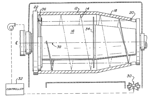
decanter centrifuge which is generally referred to by the
numeral 10. As illustrated in Figure 1, the decanter
centrifuge 10 includes a bowl 12 and a screw conveyor 14.
The screw conveyor 14 includes a series of conveyor
flights which are mounted on a conveyor hub 16. The
screw conveyor 14 rotates inside the howl 12 at a rela-
five differential speed with resg>ect to the bowl so as to
push the separated solids material (not shown) along the
length of the inside bowl wall towards the conical or
beach section 18. At the top of the beach 18 is a solids
discharge outlet or opening 20 having a weir surface
thereon. The front hub 22 on the bowl is positioned at
the opposite end of the bowl 12 from the solids discharge
20. As illustrated in Figure 2, the bowl hub 22
generally includes a liqua.d discharge outlet 24 having a
liquid discharge weir plate 26 thereon. The operation of
30, the decanter centrifuge is controlled as a function of
the sol.~ds concentration which is discharged through the
solids outlets 20. A viscosity meter 30 or the like is
positioned ~wxthin the discharge chute in the casing 28
for the decanter centrifuge 10. The meter 30 measures
the viscosity or other parameters of the solids discharge
and sends a signal to a controller 32. The controller
WO 92/Z 1445 Pd_'T/US91 /07306
32, in turn, sends a signal to other elements of the
centrifuge to control the speed of rotation of the con-
veyor 14, the feed rate into the decanter centrifuge 10,
the inflation of the inflatable dam structure, etc., so
as to vary the operational characteristics. Alternately,
a meter could be positioned to measure viscosity,
turbidity, or other parameters of the liquid discharge
and send a signal to controller 32.
As illustrated in Figure 1, a baffle 34 is
l0 usually mounted on the conveyor hub 16. The baffle 34
extends to a radial position proximal to the inside wall
of the bowl 12 and usually adj scent the j oinder of the
cylindrical section with the beach 18. The baffle 34 is
intended to operate in accordance with Lee U.S. Pat. Na.
3,"795,361. Adjacent to the bowl hub 22 is provided an
inflatable dam structure 36. The structural elements of
inflatable dam of the present invention are described in
detail below by making reference to the remaining
figures.
2~ Figure 2 illustrates in cross-section, one
embodiment of inflatable dam 36 as contemplated by the
present invention. The inflatable dam 36 is positioned
adjacent to the liquid discharge outlet 24 within the
bowl hub 22 . Tt is generally contemplated that more than
one liquid discharge outlet 24 is provided in the bowl
hub 22. The inflatable dam 36, as illustrated, is con-
tinuous and/or annular, circling around the central lon-
gitudinal axis 38 of the bowl 12 and the conveyor 14.
The weir plate 26 is fixed to the outside surface of the
3~: bowl hub 22 so as to define a position that is radially
outward ~~~~~of position of dam 36 in its collapsed or
deflated condition. The deflated dam 36 is preferably
set to provide a below spillover type operation (i.e.,
the liquid weir surface being radially outward of the
solids discharge weir). Dam structure 36 is inflatable
so as to change the relative radial position of the pond
WO 92/21445 ~~G~ ;y PCf/US91/07306
~.~ ,_
surface 40. This change in the radial position of the
pond surface 40 is created by the inflation of the
bladder portion 58 of inflatable dam 36 to the position
illustrated in dotted lines in Figure 2. This inflation
of dam 36 can result in an above spillover condition.
The inflation of dam 36 is created by supplying
a control liquid from a head tank, a pump, or the like
(not shown) into the centrifuge. In Figure 2, the con-- w
trol liquid is introduced through the pillow block 42.
to The control liquid is input through passage 44 which
communicates with pas,.~ageway 46. Passages 44 and 46 are
located within.the stationary portions of the centrifuge
mounting structure. The control liquid is then directed
into collection trough 48 and internal passageway 49
within the rotating structure attached to the bowl hub
22. The control liquid is directed from trough 48 and
passageway 49 into one or more radially projecting pas-
sageways 5a extending through the bowl hub 22. Radial
passageways 50 connect to the inflatable dam structure 36
2 J through axial passageways 52 . Inflatable dam 36 includes
a mounting block 54 connected to the inside surface of
bowl hub 22. Each axial passageway 52 extends through
the bowl hub 22 and communicates with passageway 56
within the mounting block 54. The proximal relationship
of the rotating structures with the stationary structures y
has not been detailed in the figures. These details are
considered to be within the skill of the art. However,
the communication structures may include seals, such as
a clipper seal or the like, for preventing the liquid
30~ discharge from contaminating the joint area.
Attached to mounting block 54 is inflatable
bladder 58. Hladder 58 is secured to the mounting block
54 by means of clamping disks 60. The bladder 58 is
generally contemplated to have a U-shaped cross-section.
A lip is provided on the projected ends or legs of the U-
shape. The bight of the U-shape projects radially
WO 92/21415 P~C'f/US91/0730b
-Z1_
inwardly and forms a weir surface for the liquid dis-
charge. When a control liquid is fed through the series
of passageways 44, 46, 48, 49, 50, 52 and 56, the bladder
58 is inflated away from (radially inward) the mounting
block 54. This inflation changes the shape of the
bhadder 58 and moves the radial position of the pond
surface 40 inward. Thus, the level of the liquid pond
surface 40 passing over the bladder 58 also changes in
radial distance with respect to the solids weir in outlet
20.
The bladder 58 illustrated in Figure 2 : includes
one or more leak bushings 62 which permit the control
liquid to pass therethrough. To control both the infla-
tion and deflation of the bladder 58, the rate or volume
of the control liquid fed into the bladder is varied.
variations in the volume of the a~antrol liquid results in
a variation of the amount of inflation of the bladder 58.
Increasing the volume of the control liquid fed into the
passage 44, increases the liquid head retained within the
radial passageway 50. The pressure created by the liquid
head, which is increased in magnitude as a result of the
centrifugal force created by the rotation of the bowl,
inflates the bladder. The control liquid because of the
pressure of the liquid head is discharged through the
leak bushing 62. Upon reaching equilibrium, the rate or
volume of flow into the input passageway 44 is equal to
the flow through the leak bushing 62. Decreasing the
flow of control liquid reduces the inflation of the
bladder and increases the relative radial position of the
3U, bladder 58. Leak bushing 62 permits the variation of the
volume o~ control liquid input through the inlet 44 to be
the controlling parameter for bladder inflation.
The leak bushing could also be provided on
passageways 50, 52, or 54 at a position radially outward
of the bladder 58. In this variation the discharge from
the leak bushings would preferably be directed outside of
WO '92/21 X145 f CT/ U~c) 1 /07306
the bowl. Mounting of the leak bushings at the most
radially inward position on the bladder will prevent air
pockets from forming in the bladder. Air pockets could
prevent deflation of the bladder.
In Figures 3 and 4, an alternate embodiment of
the centrifuge l0' is illustrated. In this alternate
embodiment, the front bowl hub 22' has been modified
along with the structure of the pillow block 42°. In
this embodiment, the pillow block 42' is attached
directly adjacent to the front bowl hub 22' . This alter-
nate mounting eliminates a substantial amount of struc-
tune which is supported inside of the pillow block 42' as
compared to that shown in Figures 1 and 2.
In °~he upper part of Figure 3, there is illus
trated an inflatable dam structure 36' which is attached
to the inside wall of the front bowl hub 22'. A notch is
formed in the bowl hub 22' so that the position of the
inflatable dam 36 is locked thereto. Mounting may be
performed by a series of bolts or the like. The bladder
58 of inflatable dam 36' on the top of Figure 3 is shown
deflated. This bladder 58 is secured by clamping disks
60 which are attached to mounting block 54° by means of
bolt 64. Inflatable dam 36' is positioned adjacent to
the series of openings 24' in the front bowl hub 22'. A
weir plate 26' is attached to the outside of the front
bowl hub 22' adjacent each opening 24' by means of bolts
66.
As shown in the lower portion of Figure 3 and
as detailed in Figure 4, the inflation of bladder 58
3~ raises the pond level 40 radially inward of the weir
surfac~~~~formed by weir plates 26', and preferably to a
position radially inward of the weir surface for the
solids discharge 20 (see Figure 1), i.e., to an above
spillover condition.
It can be seen that the relative radial dis-
tance between the inflated bladder 58 on dam 36' and the
WO 92/21445 PC I'/'US91 /07306
'13
weir surface defined by weir plates 26' is relatively
small. However, this factor may be significant in the
operation of the centrifuge. The tangential velocity of
the discharging liquid from a decanter centrifuge deter-
s mines much of the horse power requirements for rotation
of the centrifuge bowl. The tangential liquid velocity
is a function of the radius of the liquid weir surface.
The position of plate 26° radially similar to the pond
surface 40 defined by inflatable dam 36° results in a
1o substantial reduction in the amount of horse power
required for centrifuge operation, as compared to having
no weir plate which would result in the liquid being
accelerated to a tangential velocity at the largest
radial dimension of the liquid discharge openings through
15 the hub 22°.
The continuous structure of bladder 58 forms an
annular weir that provides advantages over discontinuous
weir structures. The pond level within the bowl is
generally a function of the flow rate over the weir star-
20 face. The increase in circumferential weir length
created by the inflatable dam 36 and 36° reduces
restriction to the discharging flow as compared to the
discontinuous weir plates. Thus, the height of the
liquid above the weir surface formed by the bladder 58 is
25 relatively lower than that which would be created by the
same flow rate over a series of weir plates or the like.
This annular structure further adds to the ability of the
decanter centrifuge 10 and 10 ° to control the pond level .
The turbulence near the front hub 22° is also reduced,
30, resulting in less re-entrainment of separated solids into
the liquid being discharged.
~s particularly illustrated in Figure 4, the
feed channels for the control liquid have been modified
in the alternate embodiment of the centrifuge l0". The
35 control liquid is directed through an inlet pipe 68 which
is attached to the pillow block 42°. Inlet pipe 68 com-
W~ 92121445 o C~ ~°; PC'~'/US91/07306
a
-14-
municates with internal channel 70 which feeds into
trough 72 in the rotating portion of the centrifuge. The
control liquid is then directed from trough 72 into the
bowl hub 22' through radial passageway 74. Radial
passageway 74 communicateu. with axial passageway 76 which
directs the control liquid into the mounting block 54'
and into the bladder 58 via feed passageway 78.
A leak bushing 62 has been illustrated in
Figure 4 but not in Figure 3. It is contemplated that a
leak bushing 62 will be placed at one or more positions
along the circumference of the inflatable dam 36' (or
36) . Again, the control liquid is directed from the leak
bushings 62 into the discharging flow~of liquid from the
pond surface 40. The number of leak bushings included of
the bladder is contemplated to be a matter of design
preference and a function of the size and preferred oper°
ational characteristics of the centrifuge.
In Figure 5 there i.s illustrated a third
embodiment of decanter centrifuge 10" operating in
accordance with the present invention. In this alternate
embodiment, the centrifuge 1.0" is contemplated to dis-
charge three separate phases of materials, two liquid
phases and one solids phase. The portion of the centri°
fuge 10°° illustrated in Figure 5 shows the discharge of
the two liquid phases. (Herein, the terms "liquid" and
'°solids" have been employed to describe the materials
which are separable from the feed liquid as a result of
the application of centrifugal force and then discharged
from the centrifuge. The liquid will typically be
30, lighter or less dense than the solids and will include a
certairi~~~portion of the feed solids that have not been
separated. In the description of two liquids, there is
a difference in dens ity between the two liquids within
the feed material. The application of centrifugal force
causes a separation between these two liquid phases.
This separation is defined as resulting in a light liquid
WC3 92/2144 PC."T/iJS91/07306
15 ~ .~. .~. ~ r l
discharge and a heavy liquid discharge. The heavier
material is typically referred to as a solids. This
solids material will usually be a mixture of solids and
liquid and is often referred to as a "heavy phase'°. The
liquid feed mixture generally includes a specific con-
centration of suspended solids or other insoluble
material therein. These solids are concentrated by the
application of centrifugal force and form a phase or
mixture of varying concentration within the bowl. This
mixture includes coarse solids, fine solids and liquid.
The liquid is often entrained within the solids. Because
of the varying density of the solids as well as the vary-
ing degrees of centrifugal force acting on those solids
within the bowl, the concentration of the separated heavy
phase/solids layer may vary within the bowl. The concen-
tration of the solids material that does not separate
from the liquid and that is di4.charged with the liquid
phase may also vary>)
The centrifuge 10" includes an inflatable dam
84 positioned at the discharge cutlet for the light
liquid phase. The light liquid flows from the pond sur
face 80 over a bladder 82 secured to the inflatable dam
structure 84 attached to the bowl hub 86. Inflatable dam
84 is similar to that illustrated in Figures 1-4. How
2~ ever, the bowl hub 86 is different in that a second open
r ing is provided for discharge of the heavier, liquid
phase. Inflatable dam 84 includes a disk 90 which pro
jects radially outward from the mounting block 92. Disk
90 serves to prevent the light liquid from discharging
through, passageway 88 intended for the heavy liquid.
An interface 96 is formed between the two
liquid phases within the bowl 12. Illustrated in Figure
5 is a portion of a solids layer 98 formed along the
inside of the bowl wall 12. The interface between the
solids 98 and the heavy liquid has been illustrated as a
generally solid line. However, this interface is contem-
W() 92/2145 ~. Pf.'T/LJS91/07306
~' ~,) r~;' ~1 -16 -
plated to be somewhat less defined than the interface 96
between the two liquid phases. Discharge of the solids
98 is made over the solids discharge weir, such as open-
ing 20 in the bowl 12 shown in Figure 1. The heavy
liquid moves under dish. 90 and over the weir surface 99
formed within the bowl hub 8~. Internal passageways 100
and 102 form the communication between the weir surface
99 and the heavy liquid discharge port 88.
Inflation of the bladder 82 causes the pond
surface 80 to move radially inward. Thin radially inward
movement will result in a radially outward movement of
the interface 9G between the light liquid and the heavy
liquid. However, upon reaching equilibrium, the two
liquid phases will maintain that relative position. The
overall increase in liquid level within the bowl will
result in an increase in pressure on the solids 98. If
operating under the Lee patent principles, the discharge
rate of the solids 98 will increase as a result of the
inflation of dam 89~, even if there are two liquids.
However, the heavy liquid discharge rate will not
increase based upon this inward radial movement of the
inflatable dam 84.
Although the inflatable dam is shown as con
trolling the pond level of the light liquid in Figure 5,
this structure may also be used to control the weir
diameter for the heavy liquid. Further, two inflatable
dams could be used on a three-phase decanter, using an
inflatable dam to control each liquid discharge. In this
modification, two independent sets of control liquid
30! passage~ays would be required.
In Figures 6-16, there are illustrated a series
of alternate embodiments of the inflatable dam of the
present invention. These embodiments are generally
illustrated in a more graphic format rather than the
detail shown in Figures 1-5.
CVO 92/21445 PCI~/U~'91/07306
_ 17 _ '' % ..;
~,
Figure 6 illustrates an inflatable dam forming
a restricting passageway. Bladder B is positioned
adjacent to the bowl wall BW and the bowl hub BH. A
discharge opening DO is provided adjacent to the bladder
B. The relative movement of the bladder B, caused by the
inflation and deflation thereof, results in a restriction
of the discharge opening DO. Thus, the pond level may be
positioned radially inward much farther than that result-
ing from the radial position of the inflatable dam
itself . A weir W is provided on the bowl hub BH at a
position radially outwardly of the bladder B so as to
reduce the overall horse power requirements of the cen-
trifuge.
The embodiment shown an Figure 7 is an alter-
nate to that contemplated by Figure C . The bladder B° is
sealed, forming a structure similar to an inner tube of
a tire and is attached to the bowl hub BH. Inflation of
the bladder B causes a restriction of the discharge open-
ing D~ adjacent to the weir surface W. Thus,, the bladder
B serves to position the pond surface at the desired
radial position.
Figure 8 shows an alternate mounting and
structure for an inflatable bladder B. Tn this embodi-
ment, the bladder B does not form a U-shaped structure as
illustrated previously, but rather has extensions in the
axial direction with respect to the center line of the
bowl.
Figure 9 shows a still further mounting struc-
ture for a bladder B of the inflatable dam of the present
invention. The bladder B is attached at opposite ends to
different locations on the bowl hub BH and the bowl wall
BW.
Figure 10 illustrates an alternate embodiment
of a bladder B'° for an inflatable dam. The bladder B°' is
shown in cross section to include a collapsible accordion
type structure. Tt is contemplated that the undulations
~o ozix ~ ~a_~ PCT/US9 ~ /07306
-18-
in the side walls of the bladder B" will permit further
radial motion of the inflatable dam than would be pos-
sible with a structure not having undulations (which
requires substantial stretching of the bladder material).
Figure 11 shows an alternate embodiment of a
mounting structure for a bladder B which provides for the
inflatable dam to close a first passageway PW1 in a dam
D located within the bowl adjacent the bowl hub BH. The
restriction to passageway PW~. by bladder B causes a
30 stepped increase in pond level up to the level of the
next passageway PW2 in dam D. This configuration is
useful during start up when the pond level P1 is desired
to be set at a below spillover. The step increase in the
passagecray from PW1 to PW2 causes a step increase to an
15 above spillover condition or pond level P2.
Figure 12 shows an alternate embodiment for the
mounting of bladder B. A dam D is provided within the
bowl on the opposite side of the bladder B from the weir
surface W on bowl hub BH. A passageway PW is provided in
20 the dam D. The bladder B form s a restriction for the
flow from the pond P to the weir 'W through passageway PW.
The amount of restriction changes the pond level. An
increase in the flow rate causes the pond to rise above
the radial level of the passageway and inflatable dam
25 formed by bladder B.
Figure 13 shows an alternate means for infla-
ting the bladder B. In this embodiment, an inlet conduit
C~ is connected via seals S into a channel C within the
bowl hub BI-i . A meter M controls the pressure ~ of the
30 control~~~.fluid through an inlet conduit CO which feeds the
radially extending channel C. In this embodiment, a gas
could be used as the control fluid to control inflation
of bladder B. If a gas were to be used as the control
fluid, leak bushings would be unnecessary.
i~VO 92~21aas ~ PCT/US9A/07306
°19~'
Figure 14 shows a further alternate embodiment
of the control liquid feed mechanism. The control liquid
is input through canduit Co into reservoir R which is
mounted on the bowl hub BH. The amount of control liquid
within the reservoir R determines the pressure within and
the inflation of bladder B and thus controls the pond
level. The control liquid exits through leak bushing L
positioned on the bowl hub BH. Having the leak bush-
ing s) L on the bowl hub BH, rather than on the bladder
B, prevents particles within the control liquid from
accumulating in the bladder B: To vary~the bladder B
inflation, the rate of flow of the control liquid is
varied, until equilibrium is reached ~t the desired pond
level. In order to maintain a constant pond level, the
input of control liquid through conduit CO must be equal
to the amount of liquid discharged through the leak bush-
ing L.
Figure 15 shows an alternate embodiment of the
structure shown in Figure 24. In this embodiment, an
accordion type bladder B" is illustrated. A feed tube F
directs control liquid into reservoir R mounted on bowl
hub BH. An exhaust tube E having a skimmer thereon
removes control liquid for the reservoir R. The skimmer
E may be moved radially by mechanical means (not shown)
to a select level within reservoir R which gives the
desired inflation of the bladder B'°. In this configure--
tion, leak bushings are not required. Deflation of the
bladder B is accomplished by moving the skimmer E
radially outward to remove the contral liquid from the
34~ reservoir R. To increase inflation, control liquid is
added to~~reservoir R and the skimmer is moved radially
inward. In the present embodiment, the flow of control
liquid from feed tube F need only be sufficient to fill
the reservoir R to the radial level of the skimmer on
tube E. The embodiments shown in Figures 23 and l5 uti~
size static pressure to maintain inflation of the
'VVf~ 92/21~1~t5
PC'~'/US91 /0'306
bladder. The other embodiments utilize a flow of control
liquid through the leak bushings to control the inflation
level.
Figure 16 illustrates a portion of an alternate
embodiment of a bladder B"' as contemplated for use with
the present invention. Included on the upper surface of
the bladder B " ° is a ridge 104 having a series of
notches 106 therein. The bladder B"' is contemplated to
serve as a weir surface similar to the patched fixed weir
described in L~al~ontagne U.S. Pat. No. 4,575,370, iden~
tified above. In this embodiment, centrifuge start up
can be controlled by flow rate of the feed as well as by
the inflation of the bladder B"' . Start up can take
place with radius "a°° of the inflatable dam being
radially inward of the solids discharge radius and the
liquid flowing through notches 106 at radius "b". This
start up condition is contemplated to provide a below
spillover pond level. ~.t normal flow rates, the licluid
discharge would flow over the ridge 104 on the surface of
bladder B " ' and create a pond level at or above radius
°'a°' . In this embodiment, the ridge 104 increases the
effective radial range of adjustment of the inflatable
dam from start up at low flow to operation at normal flow
rates.
Illustrated in Figures 17 and 18 is a further
s embodiment of the present invention. In this embodiment
the centrifuge 10 " ' includes an inflatable dam 1.10
similar to that shown in Figures 1-4. However, the cen-
trifuge 10' " includes a bowl 112 and its corresponding
bowl hub 122 which are attached directly to the gear box
housing~~~l4. The gear box housing 114 includes the gear
arrangement or other structure 116 which defines the
differential speed of rotation between the bowl 112 and
the conveyor 13.8. The mounting of the gear box housing
114 and its corresponding gear box 11~ adjacent to the
bowl hub 122 permits the gear box structure and the cen-
WO 92121445 PCT/US91107306
_ 21 _ ~-P -~ .~
~ c7 r;
.~ ~ r, ,~ ~,,~
trifuge bowl to be positioned between the bearings at the
opposite ends of the centrifuge. Thus, the amount of
structure cantilevered outside of pillow block 142 is
substantially reduced. In a vertical centrifuge, mount--
ing of the gear box adjacent the bowl hub is also
possible. However, only a single bearing is typically
used in this type structure.
As illustrated iri 1:'igure 17, the control liquid
for the inflatable dam 110 is input through opening 144.
The control liquid passes through passageway 146 and into
trough 248. Thereafter, the control liquid is directed
through passageway 149 and passageway 150 and into the
gear box housing 114 through transverse passageway 120.
Transverse passageway 120 communicates with a separate
passage 124 within the bowl hub 122. Thereafter, the
control liquid is directed into the inflatable dam 110
via radial passageway 126. The control liquid determines
the height of inflation of the bladder 128 by means of
the pressure resulting from the volume of control. liquid
directed through input 144.
The ability to~mount the gear box housing 114
and its corresponding gear box 116 is created by the fact
that there are no weir plates mounted on the outside
periphery of the bowl hub 122. Thus, the gear box hous~
ing 114 can be mounted directly to the bowl hub 222. The
transverse passageway 120 is sealed with respect to the
bowl hub 122 by seals 132 and with respect to the side
wall 134 of the gear box 116 by seals 136. The liquid
from the pond surface 138 is directed over the inflatable
30; dam 110, and into axial discharge opening 140. Axial
discharge opening communicates with radial discharge
opening 152 which extends through the bowl hub 122.
Previously, mounting of the gear box directly
to the bowl hub required the pond to be set at a radial
level outside of the gear box hou,ing. The relationship
of the bowl diameter to that of the gear box housing
W() 92/21445 P(.'f/~J~91/073(~6
~, -22-
6~~~~
often limited the overall depth of the pond in the bowl.
Alternatively, the weir plates would be required to be
positioned inside of the bowl so as to direct the liquid
though channels inside the bowl hub or the like. The
mounting of weir plates inside the bowl limits
adjustability of the pond since the bowl hub would be re-
quired to be removed in order to reset the pond level.
The inflatable dam, which is adjustable while the centri-
fuge is operating and which is positioned inside of the
bowl, permits the position of the pond within the bowl to
be radially inward of the housing. for the gear box.
The path of radial discharge opening 152 within
the bowl hub 122 is more particularly illustrated in
Figure 18. A series of axial discharge openings 140 are
provided around the center line or axis of rotation of
the centrifuge IO" ° . The path of the discharging liquid
as it exits the pond surface :138 and flows over the
inflatable dam 110 is axial through the openings 140.
However, this discharging liquid also includes a rote-
tional component as a result of the rotation of the bowl
112 and bowl hub 122. The direction of rotation of the
bowl hub 122 is identified in Figure 18 by the arrow
numbered I54. As the liquid discharge exits opening 140, ,
the flow moves radially outward from the center line of
the centrifuge IO° " . However, the tangential speed of
the liquid is that speed of the bowl at the radius of the
openings 140. As the liquid continues to progress
radially outward through passageway I52, the tangential
speed of the bowl hub 122 increases as the radius
30, increases. Thus, the speed of the liquid lags behind the
_,
rotation~~of the bowl. The relative radial path of the
liquid with respect to the~bowl is generally designated
by the arrows numbered 156 in Figure 18.
As shown in Figure 18, radial discharge opening
152 is skewed with respect to a radius 158 extending. from
the center line of the centrifuge 10 " '. The axial dis
WO 92/2144j a PC'~'/US91/07306
~~~,~~~>~~
-23-
charge opening 140 lies along radius 158 and defines the
initial position of the discharge for the liquid. The
flow of liquid discharge is contemplated to be directed
in such a manner so as not to impinge upon the side wall
160 of passageway 152, but may impinge upon the opposite
side wall 162. If the liquid were to impinge upon side
wall 160, the liquid would retard the rotation of the
bowl, which could increase the power requirements for
rotation. Although the liquid pathway 156 may not neces-
sarily increase the rotation of the bowl hub 122 as
liquid is directed along side wall 162, the additional
power requirements that may result from a substantially
radial passageway are eliminated b~ the structure of
passageway 152.
In Figures 19 and 20 there is illustrated a
still further embodiment of a centrifuge 10"°' having an
inflatable dam as contemplated by the present invention.
In each of the embodiments discussed above, the inflation
of the bladder will increase t;he height of the fluid
directed against the side wall of the bladder. Thus, the
inflation of the bladder results in an increased force on
the bladder in the axial direction due to the increased
height of the pond. If the range of radial variation of
the pond as created by the inflatable dam is contemplated
to be large, it may be necessary to include multa.ple
levels of inflation so as to restrict the axial force
against the bladder. .
In Figure 19, the centrifuge 10"" includes a
first inflatable dam 170 mounted radially outward of a
30. second dam 172 which also includes an inflatable con
struct'ion. Both dam structures 170, 172 are positioned
on mounting block 174 attached to the bowl hub 176. The
bowl hub 176 includes a series of passageways 178 for
discharge of the liquid from the centrifuge 10"". At
start up or under certain operational conditions, the
flow of liquid from the pond 180 is directed through
W~ 92/21445 P(.'T/US91/073~6
;., -24-
4~ '~~;. ~n $'~
openings 182 in the mounting block 174, past dam 170 and
through the discharge passageways 178. In this type
operation, the radial position of the pond 180 is deter-
mined as a function of the level of weir plates 184 adja-
cent discharge passageways 178 and the restriction to
flow formed by the inflation of dam 170 adjacent passage-
ways 182.
As illustrated in Figure 20, the restriction to
flow through passageway 182 created by inflatable dam 170
may be so great as to raise the level of the pond 180 to
the radial position of the second inflatable dam 172.
Upon the pond 180 reaching this second level, the control
is accomplished primarily as a function of the inflation
of dam 172. It should be noted, however, that the strut-
ture shown in Figures 19 and 20 may successfully operate
with flow being directed through passageway 182 and over
the second dam 172. In this regard, dam 170 serves as an
inflatable valve while limiting the overall inflation
reexuired to control the radial peasition of the pond from
the level of weir plates 184 to the level of dam 172.
It should also be noted that, although the
embodiments of the inflatable darn as shown herein are
mounted within the bowl, it is contemplated that the
inflatable dam could be placed adjacent to the bowl hub
outside of the bowl. This alternate structure renders
the separate weir plates unnecessary.
The present invention may be embodied in other
specific farms without departing from the spirit or
essential attributes thereof and, accordingly, reference
30, should be made to the appended claims, rather than to the
foregoing~specification, as indicating the scope of the
invention.