Note: Descriptions are shown in the official language in which they were submitted.
~:t ~.vf~~~~u
This invention relates to tamper indicating Dackage.
Buckgrour~d an3 Summary of tla:e Iraver~t.aon
In packaging o~ containers having closures thereon,
it has been common to provide tamper indicating packages wherein
the tamper indicating band is connected to the closure along a
weakened line provided by a plurality of bridges or a scoreline
and interengaging means between the band and the container are
such that when the closure is unthreaded from the container,
the band is severed along the bridge portions to indicate that
the closure has been tampered with.
In U.S. Patent No. 4~394,918 issued to Jean ~ressen
on July 26, 1983, a threaded closure carries a hold ring that
is joined to the bottom of the cap skirt by a series of breakable
tabs and the hold ring has an inside diameter that is at least
eQua1 .to the outside diameter of the cap skirt. A plurality
of lock lugs supported on the ring are inclined upwardly and
inwardly and are intended to hook behind a collar or mating ring
on the container neck to prevent the hold .ring from being lifted
off the container neck when the cap is unscrewed.
z0 In U.S. Patent No. 4,550,844, having a common assignee
with the present application, there is disclosed and claimed
an arrangement wherein a continuous annular flange extends from
the lower end of the tamper indicating band and is inclined
upwardly and inwardly. Such an arrangement is effecti're but
--1-
has the disadvantage in that continuous flange requires excessive
force to apply the closure to the container in certain extreme
tolerance conditions.
In an effort to reduce the force required to apply
the closure, it has heretofore been suggested in U.S. Patent
No. 4,65,657 that the free edge of the continuous annular
flange be provided with a plurality of segments to facilitate
application of the closure.
U.S. Patent No. 4,807,771 proposes the use of a
plurality of spaced-apart ring segments on the tamper indicating
band to define independently foldable ring segments and a
plurality of resilient tabs connected to each end of each ring
segment so that the .free ends of the tabs bear on the bead or
ledge of the container.
In U.S. Patent 5,00,788, having a common assignee
with the present application, there is disclosed a tamper
indicating package comprising a container having a neck with a
threaded finish, an annular bead on the neck, a plastic closure
which includes a base wall and a depending peripheral skirt
having threads interengaging the threads of the container, and
a tamper indicating band attached to the skirt by a plurality
of weakened portions defining a line of severing. An annular
flange extends axially -upwardly and inwardly from the tamper
indicating band toward the base wall of the closure and comprises
a first continuous annular flange portion connected to the band
-2-
s~~~~~.~~~~~a
by a hinge portion and a second portion which has free ends of
the segment portions engaging beneath the bead on the container
when the closure is threaded onto the container. In one form,
the second portion comprises a plurality of segment portions
extending upwardly and inwardly from the first continuous
portion. In another form, the second portion comprises a second
continuous flange portion, The flange is bent intermediate its
ends so that the second portion extends inwardly at a greater
angle than the first continuous flange portion.
Among the objectives of the present invention are to
provide an improved tamper indicating closure cahich is
constructed and arranged to be easily applied to a container
and function effectively in allowing the tamper band to separate
from the closure during removal, and thus further inhibit
tampering.
In accordance with the invention, the tamper
indicating package comprising a container having a neck with a
threaded finish, an annular bead on the neck below the threads,
a plastic closure which includes a base wall. and a depending
peripheral skirt having threads interengaging the threads of
the container, and a tamper indicating band attached to the
skirt by a plurality of weakened portions defining a line of
severing. An annular flange extends axially upwardly and
inwardly from the tamper indicating band toward the base wall
of the closure and comprises a first continuous annular flange
. W 3--
portion connected to the band by a hinge portion and a second
portion. The second portion comprises a plurality of segment
portions extending upwardly and inwardly from the first
continuous portion. The flange is bent intermediate its ends
so that the second portion extends inwardly at a greater angle
than the first continuous flange portion. The segment portions
are separated by narrow slits such that when the closure is
fully applied on a container, and the closure is rotated to
remove the closure, the free ends of the adjacent segment portion
engage a bead on the container and are moved radially inwardly
and the sides of the slits adjacent the free ends contact one
another in an interfering manner. This contact between the
adjacent free ends of the segments strengthens the flange so
that it is more difficult to invert the flange to its molded
condition which would allow removal of the closure without
severing the tamper band. The slits between the segments allow
for easier application of the closure to a container finish than
a closure with a continuous flange, by not having the high
tensile stress induced in the continuous flange as it is stretched
over the container bead. However, the slits become closed at
the free ends during closure removal, and act much like a
continuous flange. That is, it is difficult to 9.nvert the
segment portions that def ine the flange as the closure is being
removed because of the added compressive force generated because
the free ends are contacting each other. This additional force
-4-
- ~~.l.~iu~~~
enhances .resistance to removal and makes it more likely that
the band will sever along the weakened line rather than become
inverted. This also inhibits tampering.
-5-
:~ :i. ~ ~ '~ 3
Descraptar~n of the Drawings
FIG. 1 is a fragmentary elevational view of a package
embodying the invention.
FIG. 2 is a vertical sectional view of the package
shown in FIG. 1.
FIG. 3 is a fragmentary sectional view of the package
on an enlarged scale.
FIG. 4 is a fragmentary sectional view on an enlarged
scale of a portion of the closure.
FIG. 5 is a fragmentary sectional view showing the
application of the closure to the container.
FIG. 6 is a sectional view of the closure as it is
molded.
FIG. 7 is a fragmentary elevat.ional view of a portion
~ of the closure shown in FIG. 5.
FIG. 8A is a fragmentary sectional view on an enlarged
scale of a portion of the closure shown in FIG. 9.
FIG. 8B is a fragmentary sectional view on an enlarged
scale of a portion of the closure shown in FIG. 8A, after it
has been formed to its final configuration.
FIGS. 9-14 are partly diagrammatical sectional views
showing the inversion of the flange from the as-molded position
to the final position in closure.
-6-
~:~_~~.~'~~~8
FIG. 15 is a schematic diagram of the inversion of
the flange on the tamper indicating band of the closure.
FIG. 16 is a sectional view similar to FIG. 3 showing
the relative position of the container and closure during
removal.
. _7_
description
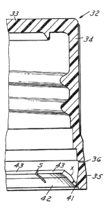
Referring to FTG. 1, the tamper indicating package
embodying the invention comprises a container 30 having a finish
or neck 31 and a closure 32. The closure 32 is formed of
thermoplastic material such as polypropylene or polyethylene
which is molded as a single unit and comprises a generally disc
shaped top or base wall 33 with a cylindrical depending skirt
portion 34 (FIG. 2>. A tamper indicating band 35 which is
generally cylindrical is connected to the peripheral skirt 34 by
a weakened line defined by bridges or scored portions of the
skirt 34, herein shown as an interrupted scoreline 36.
Interengaging threads 32a, 3la,are provided on the closure and
neck and cooperate to apply and hold the closure in position on
the container. The container 30 includes an annular bead 37.
Referring to FIGS. 2, 3, and 8B, an annular flange 40
is connected to the innex surface of the tamper indicating band
by an integral hinge portion 41 that is spaced so that it extends
radially inwardly of the inner surface of the tamper indicating
band 35 and the flange 40 extends upwardly and inwardly toward
the base wall of the closure. The flange 40 includes a first
continuous annular flange portion 42 that extends from hinge
portion 41 at a slight angle radially inwardly before the closure
is applied to the container. The flange 40 further includes a
second portion in the form of a plurality of integral
circumferentially spaced segment portions 43 extending from the
_g_
free edge of the first continuous flange portion 42. The flange
40 is bent at X intermediate its ends so that the free ends of
the segment portions 43 extend at a different and greater angle
with the axis of the closure than the first continuous flange
portion 42 of the annular flange 40. The annular flange portion
42 thus has a first pivot or hinge relative to the band 35
through hinge portion 41 and the segment portions 43 have a
second hinge with respect to the remainder of flange 40 at X.
The first continuous flange portion 42 extends axially at a
very small acute angle with respect to the band 35 so that it
is substantially vertical before the closure is applied to the
container.
The width of each segment portion 43 is at least
several times greater than the thickness at its smaller cross
section. The segment portions are generally rectangular and
closely spaced apart by narrow slits S such that the segment
portions comprise the major portion of the second portion.
Preferably, the sides of the slots are parallel. The width of
the slits S preferably ranges between 0.005 and 0.010 inch.
The number of segment portions 43 is preferably eight but may be
as few as four. The slits S pre:Eerably extend from the free edge
of the segments beyond the bend line X so that the length of
the segment portions 43 is greater than the corresponding length
of flange portion 42. Satisfactory results have been achieved
where segment portions 43 of the flange 40 comprise about 60~
. _9_
~~1~~~~~~
of the flange 40 while,the flange portion 42 comprises about
40~. However, the length of the slits may vary. It is essential
that the continuous flange portion 42 have a sufficient dimension
or length so that the flange 40 will remain inverted, without
heat forming and curing, as hereinafter described.
As shown in FIG. 5, when the closure 32 is applied to
the container 30, the continuous flange portion 42 first engages
the annular bead 37 on the container 30 and flexes the flange
40 outwardly. During application, the first continuous portion
flexes radially outwardly and the free ends of the segment
portions 43 may contact the inner surface of band 35 during the
application process. Further threading of the closure on the
container causes segment portions 43 t~ flex radially inwardly
beneath the bead 37 of the container 30 (FIG. 3). When the
closure is applied, the first continuous flange portion 42 is
substantially vertical and the free edges of segment portions
43 may engage the neck of the container below bead 37. The width
of the slits is such that, when the closure is fully applied to
a container, the free ends of adjacent segment portions 43 may
contact one another in an interfering manner to inhibit tampering
with the closure.
It has been found that this closure, which forms part
of the tamper indicating package, requires a substantially lower
application force in applying the closure and yet effectively
provides the desired tamper indicating protection. It is
_l0_
believed that the considerable reduction in application force
to pass over the bead on the container is achieved by reducing
the hoop strength of the flange 40 toward its extremity. It
is preferred that the bend in the flange 40 be at or near the
juncture of the segment portions 43 with the flange portion 42.
In such an arrangement, the segment portions 43 are at a thickness
at the bend line X such that they are able to bend approximately
along hinge line X. A radially outward force on the tips of
the segment portions 43 will first cause bending at the second
hinge line X and thus allow easier deflection of the segment
portions 43 of the flange 40, thereby reducing application
force. Where the length of the slots S is such that the base of
the slots is intermediate the bend line X and the free ends of
the segment portions 43, the segment portions 43 may flex
adjacent the base of the slots that define the segment portions.
As shown in FIG. 2, when the closure is rotated to
remove the closure from the container, the free edges of segment
portLons 43 engage the bead 37. Continued rotation of the
closure 32 causes the flange 40 to bend along the line X and
bring the segment portions 43 into engagement with the inner
inclined surface of band 35 tFIG. 16). Upon further rotation
of the closures the free ends of adjacent segment portions are
moved radially inwardly by the further engagement with the bead
37 causing the sides of the slits S of substantially all the
segment portions to contact one another adjacent the free ends.
-11-
~ _~ ~' U ~~
This contact between the adjacent free ends of the segments 43
strengthens the flange 40 so that it is more difficult to invert
the the flange 40 to its molded condition (FIG. 8A) which would
allow removal of the closure without severing the tamper band
35. The slits S between the segments 43 allow for easier
application of the closure to a container finish than a closure
with a continuous flange, by not having the high tensile stress
induced in the continuous flange as it is stretched over the
container bead 37. However, the slits S become closed at the
free ends during closure removal, and act much like a continuous
flange. That is, it is difficult to invert the segment portions
43 that define the flange 40 as the closure is being removed
because of the added compressive force generated because the
free ends are contacting each other as the flange 40 is being
forced inwardly and downwardly. This additional force enhances
resistance to removal and makes it more likely that the band
will sever along the weakened line 36 rather than become inverted.
This also inhibits tampering. Further rotation causes the band
to be severed along the scoreline 36.
Although the closure could, by complex molding
apparatus, be made to the final configuration as shown in FIG.
4, it is preferred that the closure be made with the flange 40
extending radially and inwardly and axially outwardly away from
the base wall of the closure (FIG. 8A). Accordingly, as shown
in FIGS. 5 and 7, the closure 32 is preferably molded by injection
_12_
.r r, :,x; (~
_~ ~~ v
molding or compression molding with the annular flange portion
42 and segments extending radially downwardly and inwardly
relative to the base wall 33 of the closure 32 with the annular
flange and segments being preferably aligned with one another.
More specifically, as shown in FIG. 7, the first hinge portion
41 connecting the annular flange portion 42 to the band 35
includes an upper inclined surface 45 that extends downwardly
and inwardly from the inner surface of band 35 and that merges
through an arc to a straight upper surface on the annular flange
portion 42 and segment portions 43. In FIG. 8A, the lower
surface 47 of the annular flange 40 is at an angle to the upper
surface so that the flange 40 becomes increasingly thicker
toward the free end. The lower surface 48 of the hinge 41 is
generally horizontal connected by small arc to the interior
surface of the peripheral skirt.
After molding to the configuration shown in FIG. 8A,
the flange 40 can be deformed to provide the flange portion 42 at
a substantially vertical angle and deform to form the bend X
and then the flange 40 may be inverted in accordance with well-
known techniques. However, it has been found by proper control
o.f the inversion process, the continuous flange portion 42 can
be deformed so that it is substantially vertical and the bend X
can be simultaneously formed during the inversion. More
specifically, by proper control of the inversion, the elastic
limit of the flange portion 42 can be exceeded to decrease the
-13-
angle which the flange .portion 42 forms with the axis of the
closure and the elastic limit of the flange at the line X can
be exceeded to form the bend desired.
Tt has been found that the inversion of the annular
flange portion 42 and segment portions 43 to form the separate
angular relationship between the annular flange portion and the
segment portion 43 is preferably achieved by a plunger or mandrel
M such as shown in FIGS. 9-14 and comprises a free end having a
cap centering cone 50, a thread location diameter for engaging
the diameter of the threads of the closure, a first inclined
portion, a pilot diameter 52 and a laterally inclined inverting
shoulder 53 that engages the segment portions to invert the
segment portions and the annular flange portion, as presently
described.
The successive steps during the inversion are shown
in FIGS. 9-14 and include the following:
a) The closure is advanced into the tooling nest
radially with respect to a machine, and is approximately located
on center by an inverting mandrel M. The mandrel M may at this
time be rotating in order to effect a subsequent scoring
operation.
b) Relative axial movement takes place between the
closure 32 and the mandrel M by cam actuation of the respective
tooling ttop and bottom).
-14-
j1 ~ l J
~~ .~. a il J
c) The .relative advance of the mandrel M to the
closure 32 initially engages the segment portions 43 of the
closure against the cap centering cone 50 (FIG. 9 ) . This action
centers the closure 32 under the mandrel M by displacing the
closure sideways as necessary to correct misalignment,
d) As the above relative movement continues, the
segment portions 43 engage the thread location diameter 51, and
the friction therebetween may impart a rotational motion to the
closure, i:E desired, such that when the segment portions 43
reach the pilot diameter 52, the closure is either at or close
to the rotational speed of the mandrel tFIG. 10).
e) As the segment portions 43 engage the pilot
diameter 52, they engage with more interference, and this is
critical for this inversion method. The hoop strengths of the
flange portion 42 and segment portions 43 direct the free ends
of the segment portions 43 toward the mandrel M, and thus ensure
that they do not slip over the inverting shoulder 53 (FIG. 11>.
Further, this interference provides further rotational drive
to the cap, if desired, and for this reason it is preferred
that the relative axial movement is in dwell at this time to
ensure that there is little or no relative rotational movement
between the closure and the inversion shoulder at the time of
inversian. This reduces the possibility of scuffing of the
tips of the segment portions.
-15-
~.~~.~C~~
Tt is desirable at this time that the thread location
diameter 51 of the mandrel engage the closure threads to hold
the closure 32 in firm concentric relationship to the mandrel M.
Further, relative axial movement of the mandrel M
with respect to the lower tooling (and closure) causes the
flange 40 to be folded downwardly, and initially to be contained
within the annular space between the pilot diameter of the
mandrel and the band 35 (FIG. 11 ) . This causes a bending within
the section of the flange 40, the center of this bending moving
in the direction downward toward the top 33 of the ( upside dawn )
closure (FIG. 12).
This action continues, whereby the bending action
passes along the flange toward its tip, and toward successively
increasing thickness of segment portions 43 (FIG. 13). At some
point in this process, the band is expanded such that the segment
portions 43 are inverted by the axial movement of the mandrel
(FIG. 13).
This action initially includes a stress in the segment
at the bend 1 ine X, which causes a permanent bend in the flange
40 toward the inside of the closure.
As the mandrel M advances further, the shoulder 52
passes through the diameter of the first hinge 41 (FIG. ~.4).
This action causes the continuous annular flange 42
to be moved such that the flange portion 42 exceeds the elastic
limit at the hinge 41 so that it remains in a substantially
-16-
~:~i~~~
vertical position in the final closure after the closure is
removed from the mandrel. This further reduces the interference
of the hinge over the tamper bead of the container to which it
is applied.
During withdrawal of the mandrel, the closure 32 is
removed by a fixed stripper (not shown) which engages the rim
of the closure 32, and extends at least 180° around the
circumference of the closure (not illustrated).
The plunge invert tooling described thus has two major
effects:
(a) reforming the flange portion 42 back toward the
closure wall 35.
(b) Forming the bend X to create a permanent bend,
to allow the segment portions 43 to project radially inwardly to
a greater angle than the first continuous flange portion 42.
It has been found that after inversion in the manner
described above, the flange 40 is in stable condition and this
has been achieved without the necessity of heating.
When the closure is applied to the container, the
projections function to deter any attempts to tamper with the
tamper indicating band by hooking a tool on the segment portions
43.
It can thus be seen that there has been provided a
tamper indicating package with an improved arrangement for
interengaging the elosure with the container so that when the
-17°-
s
~~~.~~u'~3
r_losure is removed the tamper indicating band remains on the
container; wherein the closure can be readily applied to the
container; and wherein the tamper indicating package effectively
minimized tampering. Furthermore, the provision of the slits
which provide for interference between the free ends of adjacent
segment portions enhance the resistancb to removal and inhibits
tampering.
_1g_