Language selection

Search

Patent 2110876 Summary

Third-party information liability

Some of the information on this Web page has been provided by external sources. The Government of Canada is not responsible for the accuracy, reliability or currency of the information supplied by external sources. Users wishing to rely upon this information should consult directly with the source of the information. Content provided by external sources is not subject to official languages, privacy and accessibility requirements.

Claims and Abstract availability

Any discrepancies in the text and image of the Claims and Abstract are due to differing posting times. Text of the Claims and Abstract are posted:

  • At the time the application is open to public inspection;
  • At the time of issue of the patent (grant).
(12) Patent Application: (11) CA 2110876
(54) English Title: GLASS CONTAINER INSPECTION MACHINE
(54) French Title: MACHINE SERVANT A CONTROLER LA QUALITE DE CONTENANTS EN VERRE
Status: Dead
Bibliographic Data
(51) International Patent Classification (IPC):
  • G01N 21/90 (2006.01)
  • G01B 11/24 (2006.01)
  • G06F 15/70 (1990.01)
(72) Inventors :
  • BALDWIN, LEO B. (United States of America)
(73) Owners :
  • EMHART GLASS MACHINERY INVESTMENTS INC. (United States of America)
(71) Applicants :
(74) Agent: SWABEY OGILVY RENAULT
(74) Associate agent:
(45) Issued:
(22) Filed Date: 1993-12-07
(41) Open to Public Inspection: 1994-06-23
Availability of licence: N/A
(25) Language of filing: English

Patent Cooperation Treaty (PCT): No

(30) Application Priority Data:
Application No. Country/Territory Date
994,777 United States of America 1992-12-22

Abstracts

English Abstract


ABSTRACT
GLASS CONTAINER INSPECTION MACHINE
An inspection machine for inspecting the outer
surface of a vertically standing container comprising
a transparent convey for conveying a vertically
standing container through an inspection location.
The support conveyor includes a diffuser plate
located to be beneath a conveyed container at the
inspection location. A beam of collimated light is
directed vertically downwardly towards the diffuser
plate, and a two-dimensional camera axially views the
bottom of the container above the diffuser plate, and
the image is processed to evaluate the circumference
of the container.


Claims

Note: Claims are shown in the official language in which they were submitted.


The embodiments of the invention in which an exclusive
property or privilege is claimed are defined as follows:
1. An inspection machine for inspecting the
circumference of a vertically standing container
comprising
means for conveying a vertically standing
container to an inspection location,
a diffuser plate located beneath a
conveyed container at said inspection location, said
diffuser plate being configured so that when the
container is at said inspection location the periph-
ery of said diffuser plate will be outwardly spaced
from the circumference of the container,
means above said container for directing
a beam of collimated light vertically downwardly
towards said diffuser plate, said beam having a
configuration selected so that when the container is
located at the inspection location the periphery of
said beam will be outwardly spaced from the circum-
ference of the container,
two dimensional camera means vertically
below said diffuser plate for axially viewing the
shadow of the protection of the bottom of a container
on said diffuser plate at the inspection location,
and
image processing means for evaluating the
circumference of the shadow of the projection of the
bottom of the container viewed by said two dimension-
al camera and accepting or rejecting the container.

2. An inspection machine according to claim 1,
wherein said conveying means displaces said container
at a constant speed.

3. An inspection machine according to claim 1,
wherein the container has a circular cross section.

-4-

4. An inspection machine according to claim 1,
wherein said conveying means comprises a transparent
conveyor and said diffuser plate comprises means for
supporting said transparent conveyor.

-5-

Description

Note: Descriptions are shown in the official language in which they were submitted.


--~ 21~0876

SPECIFICATION
GLASS CONTAINER INSPECTION MACHINE
, ~ :' :,
The present invention~relates to the inspection
of cylindrical glass ware for malformations, -
dimensional variations and defects.
Glass containers are conventionally produced in
an I.S. (individual section) machine from discrete
gobs of molten glass. Each gob is first operated on
in a blank mold, which has opposed side portions to
form a parison and then the parison is blown into the
finished container in a blow mold which also has
opposed side portions. Where these opposed side
portions of the blow mold come together a bottle seam
will be formed and can usually be observed in the
formed container. This seam can be unacceptably
noticeable or a thin "fin" of glass can be formed at
the seam and extend partially or completely along the
seam. In either case, the container should be
rejected upon inspection. Current inspecting
techniques can not find such fins to an acceptable
degree.
It is accordingly an object of the present
invention to provide an inspecting machine that can
to an acceptable degree determine that a fin is
present so that the container can be rejected~ ~
Other objects and advantages of the present ;
invention will become apparent from the following
portion of this specification and from the
accompanying drawings which illustrate in accordance
with the mandate of the patent statutes a presently
preferred embodiment incorporating the principles of
the invention.
Referring to the drawings: ;
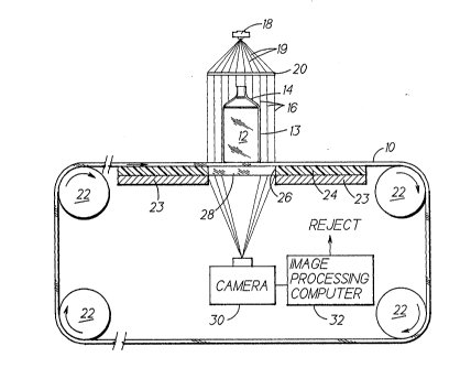
Figure 1 is a schematic showing of an
inspecting machine made in accordance with the
teachings of the present invention;
Figure 2 is a view representing the bottle

~-^` 21~087~

shown in figure 1, as seen by the camera;
Figure 3 is a view similar to that of figure 2
showing how an out of round bottle might appear; and
Figure 4 is an alternate light path to the
camera.
The inspecting machine has a conveyor 10 onto
which containers 12 are deposited by a feeder (not
shown). Each container has a cylindrical form 13
extending vertically from the bottom of the bottle
upwardly to the neck portion 14 (the axis of the
bottle is vertical). The conveyor moves continuously
and during its displacement the container becomes
located at the illustrated inspection location where
collimated light 16 passes vertically downwardly over
the container. A Fresnel lens 20 receives light 19
dispersing from a short arc flash tube 18 to form the
collimated light beam 16. As shown in figures 2 and
3 the footprint of the collimated beam on the
conveyor is selected so that for any conveyed bottle,
an annular band of light will surround the bottle.
The conveyor is a one-piece, seamless, belt
cast from transparent urethane and is driven by a
drive system 22. It is supported by a metallic plate
23 which is covered with Teflon 24. Flush with the
surface of the strip and secured within an opening
26, is a diffuser plate 28. A two-dimensional camera
30 viewing vertically upwardly views the bottom of
the container through the diffuser plate and sees the
collimated light footprint. The sensed image is
evaluated by an image processing computer 32. Such
an image processing computer will evaluate the
circumference (or outline, perimeter, outside edge,
edge) of the image of the bottle as cast onto the
diffusing surface by the collimated beam as shown in
figure 2 and determine the presence of a fin 34
(figure 2) or an unacceptable out of round shape
using conventional technology. As shown in figures
-2-

J
~-~ 21108~6
2 and 3, the bottom of the container may appear
totally black. The computer can then issue a signal
to re~ect the bottle. The inspected container will
then leave the conveyor for further processing by
structure not shown. The inspected bottle is
illustrated as circular in cross section in figure 2
but a bottle which is not intended to be circular in
cross section (oval, as shown in figure 3, for
example) can also be similarly inspected.
While the camera is vertically below the bottle
in figure 1 it can be located elsewhere by the use of
mirrors. For example, the camera can look vertically
downwardly as shown in figure 4 with the use of a
pair of 45 mirrors 38. Additionally, while the
conveyor is shown as transparent resting on a
diffusion plate, the conveyor could be the diffusion
medium and the support plate could be transparent.
.~ :.
.~
' ' ' ' ~" `
, .
.. ...

.'.' '.

. ' ':

:"

I
~
:
,,


~61)~ PC


.'


Representative Drawing
A single figure which represents the drawing illustrating the invention.
Administrative Status

For a clearer understanding of the status of the application/patent presented on this page, the site Disclaimer , as well as the definitions for Patent , Administrative Status , Maintenance Fee  and Payment History  should be consulted.

Administrative Status

Title Date
Forecasted Issue Date Unavailable
(22) Filed 1993-12-07
(41) Open to Public Inspection 1994-06-23
Dead Application 1996-06-09

Abandonment History

There is no abandonment history.

Payment History

Fee Type Anniversary Year Due Date Amount Paid Paid Date
Application Fee $0.00 1993-12-07
Registration of a document - section 124 $0.00 1995-03-17
Owners on Record

Note: Records showing the ownership history in alphabetical order.

Current Owners on Record
EMHART GLASS MACHINERY INVESTMENTS INC.
Past Owners on Record
BALDWIN, LEO B.
Past Owners that do not appear in the "Owners on Record" listing will appear in other documentation within the application.
Documents

To view selected files, please enter reCAPTCHA code :


To view images, click a link in the Document Description column. To download the documents, select one or more checkboxes in the first column and then click the "Download Selected in PDF format (Zip Archive)" or the "Download Selected as Single PDF" button.

List of published and non-published patent-specific documents on the CPD .

If you have any difficulty accessing content, you can call the Client Service Centre at 1-866-997-1936 or send them an e-mail at CIPO Client Service Centre.


Document
Description 
Date
(yyyy-mm-dd) 
Number of pages   Size of Image (KB) 
Office Letter 1994-07-05 1 42
Representative Drawing 1998-08-18 1 14
Description 1994-06-23 3 187
Drawings 1994-06-23 1 50
Claims 1994-06-23 2 113
Abstract 1994-06-23 1 60
Cover Page 1994-06-23 1 69