Note: Descriptions are shown in the official language in which they were submitted.
YOKE CASTING FOR A DRAWBAR ASSEMBLY
5 ~
FIELD OF THE INVENTION
The present invention relates, in general, to a yoke used in
a slackless drawbar system for connecting adjacent ends of a pair
of railway cars together, in a substantially semipermanent manner,
and, more pzrticularly, this invention relates to a yoke casting
formed 2s an integral single piece member for use in such drawbar
assembly.
CROSS REFERENCE TO RELATED APPLICATIONS
This patent application is closely rel2ted to a patent
application titled " FRONT DRAFT STOP FOR USE IN A DRAWBAR ASSEMBLY"
and a patert application titled "RAILWAY CAR S~PCKLESS DRAWBAR
PSSEM~LY", each of these patent applications is being filed
concurrently herewith and they are assigned to the same assignee.
BACXGROUND OF T~E IMVENTION
As is well known, railway cars are connected together by
couple- me~Ders. Such couplers m2y be conventional couplers,
articulated couplers or drawbars. Conventioral couplers 2re
independen' units disposed on an end of each car which interconnect
with cne 2nother, between adjacent cars, to form a connection.
Drawbar assemblies are integral units which extend between the ends
of two adjacent cars to form a semlpermanent connection
therebetw2cn.
~.~
- 2111258
In either instance, however, a shank end of the coupler or
drawbar will extend into the center sill of a railway car where it
is secured so as to transmit longitudinal forces to the car during
in track service.
Certain prior inventions have been directed to improvements in
the center sill construction for receiving primarily conventional
couplers. However, these improvements may also have application in
receiving couplers in a slackless system. By slackless, it is
meant that the drawbar (or coupler) is received within the center
sill in a manner to m; n;m; ze longitudinal play or movements.
However, because it is important for successive railway cars in a
train to be able to accommodate relative movement between cars when
curves and inclines are negotiated, there must be provision for
each car to move in pitch, yaw and roll modes with respect to the
coupler member. Moreover, there must be a provision to
periodically remove the draft components for repair and replacement
of parts and, in connection with drawbar systems, to disconnect
connected cars.
In a slackless system, the coupler member is held in a way to
eliminate, or m; n;m; ze, longitudinal movement with respect to the
railway car body. This may be done by providing a tapered wedge
between a rear wall of a pocket casting (secured in the center
sill) and a follower block which rests against the butt end of the
coupler member. The wedge tends to force the follower block away
from the pocket casting end wall and firmly against the butt end of
the drawbar member shank. When cars are being pushed, during
21112~
operation, the longitudinal forces will cause compression of the
drawbar member against the follower block, tapered wedge and pocket
end wall.
Conversely, when the railway cars are being pulled, the
longitudinal forces tending to separate the drawbar from the pocket
casting are countered in some systems by a draft key which is a
metal bar that extends laterally of the car center sill through
slots in the sidewalls of the center sill and a slot in the shank
of the coupler member and in other slackless drawbar systems by a
connecting pin.
In a slackless drawbar system, the drawbar is held tightly
between the bearing block and follower block by operation of the
tapered wedge which separates the pocket casting and follower block
and compresses the follower block against the drawbar to force the
latter against the bearing block and follower block. However, the
mating faces of the follower' block and drawbar are preferably
curved to permit the drawbar to pivot slightly both vertically and
laterally and to permit the car to roll with respect to the
drawbar.
Prior to the present invention, the yokes designed for use
only with slackless drawbar assemblies have generally been
manufactured from a plurality of pieces. This makes the
installation of the yoke more difficult. Furthermore, use of
separate pieces will tend to weaken the structure.
211~2~8
SUMMARY OF T~IE lNV~'~'l'ION
The present invention provides an integral single piece yoke
casting for connecting one end of a slackless drawbar to a
predetermined end of a railway car. Such drawbar forms a part of a
slackless drawbar connection system that is used to connect
adjacent predetermined ends of a pair of railway cars together, in
a substantially semipermanent manner. Such integral single piece
yoke casting includes a first vertically disposed generally
rectangular shaped side wall portion having a first predetermined
length. Such first side wall portion includes a front face portion
which is engageable with at least a portion of a rear face of a
first vertically disposed front stop member. The first front stop
member being secured within a longitudinal opening of a center
sill member. Such yoke casting further has a second vertically
disposed generally rectangular shaped side wall portion having a
second predetermined length. This second side wall portion also
includes a front face portion which is engageable with at least a
portion of a rear face of a second vertically disposed front stop
member secured within such longitudinal opening of such center sill
member axially opposite such first front stop member. The yoke
casting has a horizontally disposed top wall portion, having a
third predetermined length and a hori~ontally disposed bottom wall
portion, having a fourth predetermined length. Such third
predetermined length of the top wall portion and such fourth
predetermined length of such bottom wall portion being
substantially longer than the first predetermined length of the
~ 21112~
fIrst side wall portion and the second predetermined length of the
second side wall portion. A first vertically disposed aperture,
having a first predetermined diameter, is formed through such top
wall portion at a predetermined location and an axially opposed
second vertically disposed aperture, having a second predetermined
diameter, is formed through said bottom wall portion at a
predetermined location.
OBJECTS OF THE INVENTION
It is, therefore, one of the primary objects of the present
invention to provide a yoke for use in a slackless drawbar assembly
which is an integral single piece casting.
Another object of the present invention is to provide a yoke
for use in a slackless drawbar system which is relatively easy to
install.
Still another object of the present invention is to provide a
yoke for use in a slackless drawbar system which will not separate
when buff and draft loads are applied thereto by in train actions
encountered.
Yet another object of the present invention is to provide a
yoke for use in a slackless drawbar system which will require less
maintenance.
A further object of the present invention is to provide a yoke
for use in a slackless drawbar system which is relatively light
weight.
An additional object of the present invention is to provide a
yoke for use in a slackless drawbar system which can be retrofitted
211125~
to existing slackless drawbar assemblies and to existing railway
cars.
Still another object of the present invention is to provide a
yoke for use in a slackless drawbar system which will enable freer
movement of the draw~ar within the yoke.
In addition to the various objects and advantages of the
integral single piece yoke casting discussed above, it should be
understood that various other objects and advantages of the present
invention will become more readily apparent to those persons who
are skilled in the coupler art from the following more detailed
description, particularly, when such description is taken in
conjunction with the attached drawing and with the appended claims.
BRIEF DESCRIPTION OF THE DRAWINGS
Figure 1 is a perspective view which illustrates all of the
essential elements of a presently preferred integral single piece
yoke casting, according to thé presently preferred embodiment of
the invention; and
Figure 2 is an exploded view partially in cross section which
illustrates the use of the integral single piece yoke casting in
one presently preferred slackless drawbar assembly.
DESCRIPTION OF THE PREFERRED
EMBODIMENTS OF THE INVENTION
Prior to proceeding to the more detailed description of the
integral single piece yoke casting, it should be noted that, for
the sake of clarity, identical components, having identical
211125~
fùnctions, have been designated with identical reference numerals
throughout the drawing Figures.
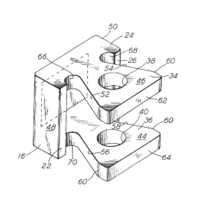
Now refer, now particularly, to Figures 1 and 2. Illustrated
therein, is an integral single piece yoke casting, generally
designated, 10 for connecting one end 12 of a slackless drawbar,
generally designated, 20 to a predetermined end of a center sill
member 14 connected to a railway car (not shown) along a
longitudinal centerline thereof.
Such drawbar 20 forms a part of a slackless drawbar connection
system, generally designated, 30. Slackless drawbar connection
system 30 is utilized, in the railway industry, to connect adjacent
predetermined ends of a pair of such railway cars together, in a
substantially semipermanent manner.
In the presently preferred embodiment of the invention, the
integral single piece yoke casting 10 includes a first vertically
disposed side wall portion 16. First side wall portion 16 has a
first predetermined length and is generally rectangular in shape.
A height of such first side wall portion 16 closely corresponds to
the height of an opening 18 in such center sill member 14. Center
sill member 14 is secured to a bottom portion (not shown) of a
railway car body member. The first side wall portion 16 has a
front face portion 22 which is engageable with at least a portion
of a rear face (not shown) of a first vertically disposed front
stop member (not shown). The first front stop member is secured
within the opening 18 of the center sill member 14, preferably by
welding.
2111-~8
The integral single piece yoke casting 10 further includes a
second vertically disposed side wall portion 24. Second side wall
portion 24 has a second predetermined length and is generally
rectangular in shape. A height of such second side wall portion 24
closely corresponds to the height of the opening 18 in such center
sill member 14. The second side wall portion 24 has a front face
portion 26 which is engageable with at least a portion of a rear
face 28 (Figure 2) of a second vertically disposed front stop
member 32. The second front stop member 32 is also secured within
the opening 18 of the center sill member 14, preferably by welding.
A third essential element of such yoke casting 10 is a
horizontally disposed top wall portion 34. Top wall portion 34 has
a third predetermined length.
Another essential element of yoke casting 10 is a horizontally
disposed bottom wall portion 36, having a fourth predetermined
length. Such third predetermined length of the top wall portion 34
and the fourth predetermined length of such bottom wall portion 36
being substantially longer than the first predetermined length of
such first side wall portion 16 and the second predetermined length
of the second side wall portion 24.
The final essential elements of the yoke casting 10 are a
first vertically disposed aperture 38, having a first predetermined
diameter, and an axially opposed second vertically disposed
aperture 40, having a second predetermined diameter. The first
aperture 38 is formed through the top wall portion 34 at a
2111258
predetermined location and the axially opposed second aperture 40
is formed through the bottom wall portion 36.
In the presently preferred embodiment of the invention, the
first predetermined length of such first side wall portion 16 will
be substantially identical to the second predetermined length of
the second side wall portion 24. In addition, in this preferred
embodiment, such third predetermined length of the top wall
portion 34 will be substantially identical to such fourth
predetermined length of the bottom wall portion 36.
It is, also, preferred that each of such third predetermined
length of the top wall portion 34 and the fourth predetermined
length of such bottom wall portion 36 will be at least two times as
long as each of the first predetermined length of such first side
wall portion 16 and the second predetermined length of such second
side wall portion 24.
In the embodiment of the invention presently being described,
the inner surface 42 of such first side wall portion 16 and the
inner surface of the second side wall portion 24 are disposed
substantially parallel to each other. Furthermore, in the present
invention, the bottom surface of such top wall portion 34 will be
disposed substantially parallel to the upper surface 44 of the
bottom wall portion 36.
As can be seen in the drawings, the yoke casting 10 is open at
each end thereof. The opening located at the rear of such yoke
casting 10 is defined by each of such inner surface 42 of the first
side wall portion 16, the inner surface of the second side wall
2111258
p~rtion 24, the bottom surface of such top wall portion 34 and the
upper surface 44 of such bottom wall portion 36.
In the preferred embodiment, the upper surface 46 of the top
wall portion 34 and the bottom surface of such bottom wall
portion 36 are disposed substantially parallel to one another. The
outer surface 48 of such first side wall portion 16 and the outer
surface 50 of the second side wall portion 24 are also disposed
substantially parallel to each other.
It is clear from the above description that such outer
surface 48 of the first side wall portion 16 and such outer
surface 50 of the second side wall portion 24 in conjunction with
the upper surface 46 of such top wall portion 34 and the bottom
surface of such bottom wall portion 36 form a generally rectangular
shape. Such rectangular shape having a predetermined height and a
predetermined width which closely correspond to a respective height
and width of the longitudinal opening 18 of such center sill
member 14.
In the presently preferred em~odiment of the invention, each
outer edge 52 and 54 of the top wall portion 34 is tapered inwardly
toward a longitudinal centerline of such yoke casting 10 at a first
predetermined angle and rearwardly for a predetermined distance
from a predetermined point 60. The predetermined point 60 is
disposed a predetermined distance from the first face 62 of the top
wall portion 34. Likewise, each outer edge 56 and 58 of the bottom
wall portion 36 is tapered inwardly toward such longitudinal center
of such yoke casting 10, preferably, at the same predetermined
~1112~8
,.~ .
angle and rearwardly, preferably, for the same predetermined
distance and, preferably, from the same predetermined point 60
disposed, preferably, the same distance from a front face 64 of the
bottom wall portion 36.
In the preferred embodiment of the invention, such top wall
portion 34 includes a first arcuately shaped portion 66 disposed
between an inner surface 42 of such first vertically disposed side
wall portion 16 and the first outer surface 52 of such top wall
portion 34 located adjacent a rear surface of the tapered first
outer surface 52 of such top wall portion 34. A second arcuately
shaped portion 68, of top wall portion 34, is disposed between the
inner surface of such second side wall member 24 and the second
outer surface 54 adjacent the rear surface of such tapered second
outer surface 54.
Also, in this embodiment, the bottom wall portion 36 includes
a first arcuately shaped portion 70 disposed between an inner
surface 42 of such first vertically disposed side wall member 16
and the first outer surface 56 of such bottom wall portion 36
located adjacent a rear surface of the tapered first outer
surface 56 of such bottom wall portion 36. A second arcuately
shaped portion of such bottom wall portion 36 is disposed between
the inner surface of such second side wall member 24 and the second
outer surface 58 adjacent the rear surface of such tapered second
outer surface.
As best seen in Figure 2, in order to ensure the requisite
movement required of the drawbar 20, the bottom surface 72 of the
2111258
......
top wall portion 34 is tapered downwardly, at a first predetermined
angle, and inwardly from a front face portion 62 of such top wall
portion 34 for a first predetermined distance. Also, the top
surface 44 of the bottom wall portion 36 is tapered upwardly, at a
second predetermined angle, and inwardly from the front face
portion 64 of such bottom wall portion 36 for a second
predetermined distance. Preferably, such first predetermined angle
will be substantially identical to such second predetermined angle
and such first predetermined distance will be substantially
identical to such second predetermined distance.
Finally, such integral single piece yoke casting 10 will be
manufactured as a steel casting. Further it is within the scope of
the present invention that certain areas of the yoke casting 10
which will be subjected to wear may be hardened.
Although a number of presently preferred embodiments of the
integral single piece yoke casting have been described in detail
above, it should be understood that various modifications and
adaptations of the instant invention may be made by persons skilled
in the railroad coupling art without departing from the spirit and
scope of the appended claims.