Language selection

Search

Patent 2111285 Summary

Third-party information liability

Some of the information on this Web page has been provided by external sources. The Government of Canada is not responsible for the accuracy, reliability or currency of the information supplied by external sources. Users wishing to rely upon this information should consult directly with the source of the information. Content provided by external sources is not subject to official languages, privacy and accessibility requirements.

Claims and Abstract availability

Any discrepancies in the text and image of the Claims and Abstract are due to differing posting times. Text of the Claims and Abstract are posted:

  • At the time the application is open to public inspection;
  • At the time of issue of the patent (grant).
(12) Patent: (11) CA 2111285
(54) English Title: CHILD'S TOY VEHICLE HAVING A SAFETY DEVICE
(54) French Title: VEHICULE JOUET POUR ENFANT MUNI D'UN DISPOSITIF DE SECURITE
Status: Deemed expired
Bibliographic Data
(51) International Patent Classification (IPC):
  • B60K 28/00 (2006.01)
  • A63G 25/00 (2006.01)
  • A63H 30/04 (2006.01)
  • B60K 26/00 (2006.01)
  • B60K 28/02 (2006.01)
  • B60L 15/40 (2006.01)
(72) Inventors :
  • RODRIGUEZ-FERRE, JOSE MANUEL (Spain)
(73) Owners :
  • RODRIGUEZ-FERRE, JOSE MANUEL (Spain)
(71) Applicants :
  • RODRIGUEZ-FERRE, JOSE MANUEL (Spain)
(74) Agent: SMART & BIGGAR
(74) Associate agent:
(45) Issued: 1997-09-09
(22) Filed Date: 1993-12-13
(41) Open to Public Inspection: 1995-06-14
Examination requested: 1993-12-13
Availability of licence: N/A
(25) Language of filing: English

Patent Cooperation Treaty (PCT): No

(30) Application Priority Data: None

Abstracts

English Abstract


It comprises a vehicle (1) including a receiver circuit
which may be enabled by the electromagnetic signal
emitted by a remote control (17), handled by an adult,
and a pushbutton (15), in series with the motor (19), to
be depressed by the child driving the vehicle. A switch
(14) breaks the supply to the receiver circuit, disabling
it, at the same time as it makes a bridge across the
power supply and the child operated pushbutton (15).

The invention is applicable to children's toy vehicles
driven by very young children, so that an adult located
remotely can break the motor supply to stop the vehicle
at any given time, for safety purposes.


French Abstract

a présente invention vise un véhicule (1) doté d'un circuit récepteur qui peut être activé par le signal électromagnétique émis par une télécommande (17) manipulée par un adulte, et par un bouton-poussoir (15), monté en série avec le moteur (19), devant être actionné par l'enfant qui conduit le véhicule. Un interrupteur (14) désactive le circuit récepteur en coupant l'alimentation à celui-ci en même temps qu'il crée un pont entre l'alimentation et le bouton-poussoir (15) actionné par l'enfant. L'invention peut s'appliquer à des véhicules de jeu conduits par de très jeunes enfants, un adulte pouvant, à distance, couper l'alimentation du moteur pour arrêter le véhicule à n'importe quel moment, à des fins de sécurité.

Claims

Note: Claims are shown in the official language in which they were submitted.


-6-
THE EMBODIMENTS OF THE INVENTION IN WHICH AN EXCLUSIVE
PROPERTY OR PRIVILEGE IS CLAIMED ARE DEFINED AS FOLLOWS:


1. A toy vehicle having a safety device, said toy
vehicle including a rolling structure having a seat, an
electric motor, a power supply formed by wet or dry wet cells
and a handle bar or steering wheel, said safety device
comprising:
a receiver circuit powered by the power supply and
fixed to said toy vehicle;
an emitter device remote from said toy vehicle;
a first pushbutton formed on said emitter device for
emitting an electromagnetic signal and enabling said receiver
circuit;
a second pushbotton arranged in series at an outlet
of said receiver circuit; and
a functional selection switch formed on said toy
vehicle in electrical connection between the power supply and
said second pushbutton, said functional selection switch
including a receiver circuit supply position in which the toy
vehicle is operable only if said first pushbutton is actuated,
and a receiver circuit interrupt position in which the toy
vehicle is operable independently of actuation of said first
pushbutton, wherein said receiver circuit is disabled in the
receiver circuit interrupt position and said receiver circuit
is enabled in the receiver circuit supply position.


-7-

2. The toy vehicle of claim 1, wherein said receiver
circuit includes an aerial antenna, a sensor, and an amplifier
all connected to a unit for energizing the electric motor.


3. The toy vehicle of claim 1, wherein said emitter
device includes an aerial antenna, an amplifier and an
oscillator.


4. The toy vehicle of claim 1, further including means
for indicating positioning of said functional selection switch
in the receiver circuit supply position.


5. The toy vehicle of claim 1, further comprising a
housing in connection with said toy vehicle for storing said
emitter device.


Description

Note: Descriptions are shown in the official language in which they were submitted.


2 ~ a ~


D E S C R I P T I O N

FIELD OF THE INVENTION

This invention relates to a child's toy vehicle having a
safety device which provides for the function to which it
is directed several advantages to be listed hereinafter,
apart from others inherent in its organization and
constitution.

RACR~ROUND OF THE lNv~N-llON

Already known in the state of the art are toy vehicles
prepared for carrying a child who becomes himself the
driver, with complete independence of control. The said
vehicles are of the type comprising an electric motor, a
power supply formed by dry or wet batteries and an
electrical circuit including an easily accessible
pushbutton closing the said motor supply circuit.

As said above, in this type of vehicle the child is
completely independent to drive and steer the vehicle in
which he is travelling, with the risks inherent thereto.
This is why this type of vehicle is for children of a
certain age, approximately from four years upwards, but
they are not appropriate for younger children, of ages
ranging from one to three years, since their lack of
driving skill could cause them problems and slight
accidents which, although not representing a serious
risk, must be avoided so as not to upset the child's
emotional state.

Thus, in the present state of the art, there is no
child's toy vehicle which, while being capable of being
driven by the child himself, includes a safety device
remote controlled by an adult, through which the motor

-~ 2 1 1 1 28 5
-- 2
supply may be cut to stop the vehicle at any one tlme, to
avoid risks that the child has no faculties to foresee or
avold, sald devlce also servlng to reconnect the motor supply
when the rlsk sltuatlon has been averted.
SUMMARY OF THE INVENTION
The present appllcant has devlsed a chlld's toy
vehlcle lncludlng a safety devlce, thanks to whlch, a very
young chlld can have access, wlthout any risk, to independent
drlvlng of the sald vehlcle, slnce an adult located remotely
has means for dlsconnectlng and connectlng the power supply to
the motor, leavlng lt lnoperatlve ln the former case and ln a
position to be energized by the chlld, ln the latter case.
Thus, the devlce conslsts of a remote control, the
function of which ls llmlted to puttlng the motor ln a state
to be connected to the power supply through a push button
operated by the chlld hlmself, or to break the supply to the
motor, leavlng lt lnoperatlve, ln splte of the chlld
perslstlng ln operatlng the vehlcle start pushbutton.
The vehlcle also lncludes a functlonal selector
swltch for the toy vehlcle whlch, ln a partlcular posltlon,
externally to be appreclated by way of a llght slgnal,
dlsconnects the remote control but leaves the vehlcle motor
completely operatlve for excluslve control by the chlld.
More speclflcally, the present lnventlon resldes ln
a toy vehlcle havlng a safety devlce, sald toy vehlcle
lncluding a rolling structure having a seat, an electric
motor, a power supply formed by wet or dry wet cells and a


72599-23

2 ~ ~ ~ 2 8

- 2a -
handle bar or steerlng wheel, sald safety devlce comprlslng a
recelver circult powered by the power supply and flxed to sald
toy vehlcle; an emltter devlce remote from sald toy vehlcle; a
flrst pushbutton formed on sald emltter devlce for emlttlng an
electromagnetlc slgnal and enabllng sald recelver clrcult; a
second pushbotton arranged ln serles at an outlet of sald
recelver clrcult; and a functlonal selectlon swltch formed on
sald toy vehlcle ln electrlcal connectlon between the power
supply and sald second pushbutton, sald functlonal selectlon
swltch lncludlng a recelver clrcult supply posltlon ln whlch
the toy vehlcle ls operable only lf sald flrst pushbutton ls
actuated, and a recelver clrcult lnterrupt posltlon ln whlch
the toy vehlcle ls operable independently of actuatlon of sald
flrst pushbutton, whereln sald recelver clrcult ls dlsabled ln
the recelver clrcult lnterrupt posltlon and sald recelver
clrcult ls enabled in the recelver clrcult supply posltlon.
The present Patent of Inventlon offers the
advantages descrlbed above, apart from others whlch wlll be
easlly gathered from the embodlment of a toy vehlcle havlng a
safety devlce, descrlbed ln fuller detall herelnafter to
facllltate an understandlng of the above mentloned


72599-23

8~


features, while disclosing at the same time several
details. For such purpose, the specification is
accompanied by drawings in which a practical embodiment
of the invention is shown as a non-limiting example of
the scope of the present invention.

BRIEF DESCRIPTION OF THE DRAWINGS

In the drawings:

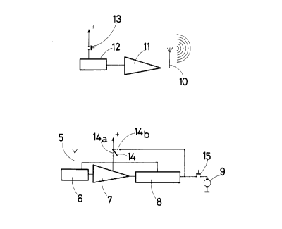
Figure 1 is a block diagram of the electronic operation
of the toy, according to one embodiment.

Figures 2 and 3 are respective perspective views of the
vehicle incorporating the receiver forming an integral
part of the toy assembly.

DESCRIPTION OF AN EMBODIMENT ACCORDING TO THE INVENTION

As shown in the drawings, the toy vehicle of the
invention comprises a structure, designated generally at
1, resembling a motorcycle, although it could adopt other
more or less fanciful forms, comprising at least wheels
2, a seat 3, for the child, and a handlebar or steering
wheel 4.

The vehicle 1 comprises a circuit receiving an
electromagnetic signal emitted by a remote control or
emitter 17, handled by an adult. The receiver circuit is
formed by an aerial 5, a sensor 6 and an amplifier 7,
connected to the unit 8 energizing the electric motor 9.

Independently there is provided the emitter or remote
control designated generally at 17, formed by the aerial
10, amplifier 11 and oscillator 12, including an
operating pushbutton 13.

2111~8~


The receiver unit installed in the vehicle 1 has a
changeover switch 14 allowing the toy to be used in one
of two optional modes.

In the first of said options, the switch is placed in
position 14a, thereby causing a LED 16 to become
illuminated. In this situation the receiver circuit is
energized and the motor 9 is operated through the
receiver 6,7,8, energized by the emitter, formed by 10,
11,12.

Nevertheless, when the start pushbutton 15 is placed in
series with the motor 9, for the vehicle motor 9 to
operate, it is necessary to energize both the remote
control, through its pushbutton 13, and the said start
switch 15 of the motor 9 of the vehicle 1.

If the adult handling the remote control operates the
pushbutton 13, but the child does not press the motor
start button 15, the vehicle motor will not operate. In
this way, the child always has the final control over the
vehicle in which he is seated.

If the child holds the pushbutton 15 depressed, the
vehicle will operate while the adult presses the remote
control or emitter button 13.

In the latter of the aforementioned options, the switch
is in position 14b, in which the LED 16 is extinguished,
the remote control receiver being disabled, since said
switch breaks the supply to the receiver at the same time
as it establishes a bridge to bypass the said receiver
portion. Therefore, the vehicle is completely operative
for exclusive control by the child, without the
intervention of the adult. In other words, if the child

2 1 1 ~ ~S-


presses the start button 15, the vehicle runs and if he
does not press it, it remains at rest.

This second option is reserved for when the child has
acquired sufficient experience in the handling of the
vehicle to be able to drive it under his own exclusive
control.

At the rear of the vehicle there is provided a housing 18
for the control 17, when not in use.

Representative Drawing
A single figure which represents the drawing illustrating the invention.
Administrative Status

For a clearer understanding of the status of the application/patent presented on this page, the site Disclaimer , as well as the definitions for Patent , Administrative Status , Maintenance Fee  and Payment History  should be consulted.

Administrative Status

Title Date
Forecasted Issue Date 1997-09-09
(22) Filed 1993-12-13
Examination Requested 1993-12-13
(41) Open to Public Inspection 1995-06-14
(45) Issued 1997-09-09
Deemed Expired 1999-12-13

Abandonment History

There is no abandonment history.

Payment History

Fee Type Anniversary Year Due Date Amount Paid Paid Date
Application Fee $0.00 1993-12-13
Maintenance Fee - Application - New Act 2 1995-12-13 $50.00 1995-10-18
Reinstatement: Failure to Pay Application Maintenance Fees $200.00 1996-12-23
Maintenance Fee - Application - New Act 3 1996-12-13 $50.00 1996-12-23
Final Fee $150.00 1997-05-12
Maintenance Fee - Patent - New Act 4 1997-12-15 $100.00 1997-11-18
Owners on Record

Note: Records showing the ownership history in alphabetical order.

Current Owners on Record
RODRIGUEZ-FERRE, JOSE MANUEL
Past Owners on Record
None
Past Owners that do not appear in the "Owners on Record" listing will appear in other documentation within the application.
Documents

To view selected files, please enter reCAPTCHA code :


To view images, click a link in the Document Description column. To download the documents, select one or more checkboxes in the first column and then click the "Download Selected in PDF format (Zip Archive)" or the "Download Selected as Single PDF" button.

List of published and non-published patent-specific documents on the CPD .

If you have any difficulty accessing content, you can call the Client Service Centre at 1-866-997-1936 or send them an e-mail at CIPO Client Service Centre.


Document
Description 
Date
(yyyy-mm-dd) 
Number of pages   Size of Image (KB) 
Description 1996-11-12 6 190
Cover Page 1997-08-29 1 41
Abstract 1995-06-14 1 18
Cover Page 1995-07-27 1 16
Claims 1996-11-12 2 51
Description 1995-06-14 5 156
Claims 1995-06-14 1 38
Drawings 1995-06-14 2 29
Representative Drawing 1997-08-29 1 4
Fees 1997-11-18 1 26
Examiner Requisition 1996-04-04 2 61
Prosecution Correspondence 1995-10-05 1 28
Prosecution Correspondence 1996-10-03 1 39
PCT Correspondence 1997-05-12 2 55
Fees 1996-12-23 2 67
Fees 1995-10-18 1 40