Note: Descriptions are shown in the official language in which they were submitted.
WO 92/~2379 P~/13S91/04203
~111 35~
PIPETTING PROBE WITH REDUCED REAGENT CARRYOVER
Backqround of the Invention
This invention relates to an improved pipett:ing probe.
Pip~tting probes are generally used in automatic diagnostic :
or analytical equipment and serve to extra t measured
quantities o~ r~agents of various types from the containers
which s~ore them and l~o dispen~e these raagents as required
~o conduGt ~he test or anaIy~is which is l~o be performed. `~
After eac:h extraction and dispensing of a parti;cular
r~agent, the pipetting probe must be care:Eully washed, both
inside and out, to remoYe all traces of that reagent in
ord~r to prevent çont~mtna~ ion ~ the ~thex reagents and
carryoYer of that re . gent into ~ubsequent tests . Since many :,
diagnostic and analyticaI tests conducted i:n: automatic -.
equipment are capable cf making~ precise raeasurements in :the
parts per~ million rang~, it is imperative that the pipetting
probe which dispenses the reagents ~or such tes~s ba -
designed such that it can be efficiently washe~ to remove
al~poten~ial: co2ltaminants to a level below the normal
~: measuremsnt range of ~he instrument.
Ac~ ordir~glyr it is an object of the present invention :
to provide a pipetting pro~e which can be efficiently washed
so as to reduce reagent carryover. It is also an object to
: provide a met~od o~ making such: a pipe~ting probe~
3 0 The present in~rention embraces an improved pipetting
prob~ wherein a portion of the interior of said probe is
etc:hed so as to crea~e fluid t urbulence therewithin during
use to improve: the washing out of residual sample fluid.
~qore partic:ularl~r, the pipetting probe of the pres~nt
W092/22379 PCT/US91/042~3
'~11135~
in~ention comprises a rigid tubular sheath tightly
circumscibing a tubular polymeric liner, wherein a portion
of the interior of said polymeric liner is etched, ~`
particularly that portion exaluding the sample region
portion. The present invention also embraces a method of
impro~ing the internal washing ef f iciency of a pipetting
probe by etching a portion of the interior o~ the pipetting
probe. In addition, the invention embracec a method of
making an improved pipetting probe by pulling a tubular :~
polymeric liner, which ~as a narrowed liner:portion formed
by a narrowing die,:into a rigid tubular sheath, and ~
~~ allowing ~he narrowed liner portion to expand against screw .
threads in the tip portion of the sheath so as to become
immovably fixed therein.
Brief Description of the Drawinas
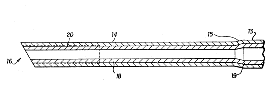
: Fig. 1 is a perspective view o~ the pipetting probe of the
pres~nt invention and depicts both the rigid sheath, with
20 its tip portion, and the polymeric liner. '~
Fig. ~a is an enlarged cross-section of the tip portion of
the rigid sheath and:depicts:the threaded section tshown by
dashed lines) and the polymeric liner portion.
Fig. 2b is an enlarged cross-section of the opposite end of
the rigid sheath and depicts the polymeric liner portion
tightly circumscribed by the main portion of the rigid
~heath and extending out therefrom.
Fig. 2c is an even further enlarged cross-section of a
fragment o~ the tip portion and depicts the threaded section
therewithin.
Fig. 3 is a cross- ection of a narrowing die and depicts a
portion of polymeric liner being drawn therethrou~h.
W092~22379 PCT/U~91/04203
~1~13~5 ` `
Descri~tiQ~ of the Preferred Embodiments
Throughout the specification and claims the te~ms
reagent and sample fluid are used interchangeably and are
S intend~d to include any fluid material used in a diagnostic
or analytical test instrument . Such fluid materials include
the sample being tested, for example patient samples, such
as blood or urine or extracts~thereof, as well as
standardized test samples, and the reagents utilized to
conduct the test(s) to be performed, for example chemical,
biochemical or biological reagents r ~including immunological
~~ r~agen~s suc~ as solutions of antibodies or antigens.
In its b~oadest application, the presen~ invention
embraces a pipetting probe compri~ing a poly~ric tuhe
having a discharge end into or from which a quantity of
sample fluid may be drawn or discharged, wherein a~portio~ :.
of the interior of said tube is etched so as to create fluid ~:
turbulence therewithin during use~to improve the washing
efficLency thereof. Pr~ferably that portion of the
polymeric tube interior which is et~h~d excludes at least :
abouk the first 20%~of said~tube at the~discharge end, more
preferably about the firct 30~ to 70% of ~aid tube at the
: discharge end. Normally, the pipetting probe will comprise
a sample region po~tion which extends ~rom the~discharge end
25 to~a pradatermined length of the polymeric tu~e. This i~ :
the portion which will hold a predetermined measured volume
: ~
of sample ~luid. It is most preferred to exclude the:sample
regisn portion from that portion o~ the polymeric tube
interior which is etched. :
It has be~n found that etching a porti~n of the
polymeric tube interior substantially increases the washing
efficiency of the probe interior. It is theorized that when
wash solu~ion i~ paæ~ed through the proba interior, it
becomes turbulent as a result of contact with the etched
interior wall. This turbulence then carries through the
W092/22379 PCT/US91/04203
2 1 1 1 3 ~ S ! ; :
non-etched portioh, which includes the sample region
portion, and assists in the removal of any traces of sample
fluid which otherwise might adhere to the smooth wall of the
probe. Without such etchin~, the interior wall is
5 substantially smooth throughout, which results in a ;
substantially laminar flow of wash fluid through the probe ~.
(near-zero fluid velocity at the waIl surface). Such
laminar flow i5 not very ~ffective at removing ~ample fluid
that adheres to the interior wall.
The washing efficiency of the pipetting probe can be
further improved by altering the inner diameter of the probe
~~ in certain sections. For example, it is particularly
advantag~ous whe~e the tip portion of the polymeric tube
(i.e. at the discharge end) has an inner diameter ~hich is `
narrower, preferably about 40 to 60~ narrower, than-the
inner diameter of the major part of~the polymeric tube.
Most pref~rably, the polymeric~tube;will also have an
intermediate portion, with an intermediate inner:diameter,
between the tip portion and the major~part of the polymeric
tube. This intermediate inner diametcr is preferably about
20 to 30% narrower than the major~part of the polymeric
tube. The particulars of this geometry will be discussed in
greater detail later.
The invention will now be more specifically described
by reference to the accompanying~drawings, with particular
emphasis on its most preferred embodiments.
The pipetting probe 10:, in its most practical form,
comprises a rigid tubular sheath ll, preferably fabricated
of stainless steel,~and a tubular polymeric liner 12,
preferably fabricated of polyfluoroethylene. The rigid
tubular sheath comprises a main portion 13 and a tip portion
14 at one end thereo~, said main portion 13 ha~ing a ~irst
inn~r diameter and said tip portion 14 having a second
inner diameter, with said second inner diameter being equal
35 to or less than said first inner diameter. Preferably said
W~92/22379 PCl/~S9~/04203
2111~
second inner diameter is less than said first inner
diameter, most prsferably about 25% less. It is also
preferred that the tip portion 14 will have an outer ~-
diameter which is less than the outer diameter of the main
S portion 13 and will be connected to said main portion
through angularly inolined neck portion 15, which serves as
a transition between the tip portion and:the main portion.
The tip portion 14 has a diccharge end 16, into or from
whîch sample~fluid may be drawn or discharged. This
discharge end 16 is preferably cut at an angle (or beveled~
to facilitate the puncturing of sealed cartridges and the
~~ dispensing of fluid~ It is also especially preferred that a
portion of the tip portion contain internal screw threads 20
for gripping the liner as will be discussed later.
In a typical pipetting probe which is proposed for use
in the SRl instrument sold by Serono-Baker Diagnostics Inc.,
the rigid tubular sheath is fabricated from 15 gauge type
304 stainless steel tubing and has the following dimensions:
Tip Portion
Length 14.0 mm (o.55 in)
I.D. - 1.14 mm (0.045 in)
O.D. ~ 5 mm (O.057 in)
Main Portion
Length - 124 ~m (4.88 in)
I.D. - 1.52 mm (O.060 in)
o.D. - 1.83 mm (0.072 in)
Neck Portion
Inclined at 13 angle from longitudinal axis
Discharge End
Beveled at 30 angle from perpendicular axis
Screw Threads
Extend 5 mm (0.2 in) from discharge end
Thread size/pitch M 1.2 x 0.25
W092/22379 PCT/US91/04203
~1113!~5'"'
The tubular polymeric liner 12 is the more critical
part of the invention since that is the part which holds the ~
sample fluid and which is the most difficult to wash of
residual sample fluid after it is dispensed. Generally, the ~-
5 polymeric liner is constructed of a flexible, inert, ~-
non-wettable material such as polyfluoroethylene. Its
len~th and inner diameter are selected ~o as to hold a
predetermined quantity of sample fluid as a minimum (i.e.
the sample re~ion portion), plus some excess to serve as a
buffer between the sample region portion and the operative
machinery to which the liner is connected (e.g. Ca~ro
''~ syringe). While thè dimensions may be varied inversely
wlthout aff~cting a change in the absolute ~olume of
material held, there is a practical ran~e of values that is ~:
15 constrained by a need to measure and deliver acc:urate
volumes, reduce pressure~drop, minimîæe surface:area, and
f it within the instrument and sheath in which it is
: utilized. This practical range of values ~ay be readily
determined and optimized by the skilled practitioner. The
outer~diameter of the polymeric liner should be
approximately equal to or slightly greater than the inner
diameter of ~he:rigid sheath (particular:ly~the main portion
~ of the sheath) so that, upon insertion, it is tightly
: circumscribed and, preferably, immovably fixed therein.: It
will be longer:~han the rigid sheath and will extend from
the discharge end 16, to which it is preferably cut flush,
through and beyond the opposite end of the sheath.
A preferred method of inserting and affixing the
polymeric liner in the rigid sheath is now described, with
particular reference to dimensions and materials that are
characteristic of those proposed for use in the
aforementioned SR1 diagnostic instrument. The sheath to
which the liner is inserted is: the one previously described.
The polymeric liner utilized consists of
polyfluoroethylene tubing (FEP tubing manufactured by
Fluortek Medical Inc., Easton, PA) with an inner diameter of
. W092/22379 PCT/US91/04203
' l 7
1.07 mm (O.042 in) and an outer diameter of 1.74 mm
(0. 068 in) . As will be app~rent, the outer diameter of this
liner is slightly greater than the inner diameter of the
main portion of tha stainle~s steel sheath, which is 1.5~ mm
tO.060 in).
A portion of the liner is dra~n through a narrowing die
17, as illustrated in Fig. 3, to provide a narrowed liner
portion 18 of 1.07 mm (0.042 in) outer diameter and 0.41 mm
(0.016 in) inner diameter.
The outer diameter of the narrowed liner portion 18 is
somewhat less than the:inner diameter of the tip portion 14,
~~ which is 1.13 mm (0.045 in), to facilitate easy inser~ion of
tha liner within the sheath. For this reason the length of
the narrowed liner portion is advantageousIy greater than
the length of the sheath.~
Upon insertion of the:narrowed liner portion through
the sheath, so that ~it extends~:through~the discharge end :
~thereof, it is pulled with the;necessary force so as to draw
the~liner into the sheath, thereby narrowing that portion of
the liner which en~ers the main portion of the sheath so as
to form an intermiediate liner~portion 19 until:that
intermediate:liner portion abuts~against~the;interior wall
of the neck portion. The intermediate~liner portion 19 will
thus be tightly circumsaribed by the main:portion 13 of the~
rigid sheath and will have a:length~and outer diameter~egual
to the length and inner:diameter of the main portion of the
rigid sheath. The inner diameter of the intermiediate liner
portion is thius redueed to 0.71 mm (0.028 in).
Ths probe is then heated to about 200F (93C) for
approximately two hours to allow the narrowed liner portion
: to expand (due to memory characteristics of the material)
: and become tightly circumscribed by he tip portion. This
: expansion increases the inner diameter of the liner within
the ip portion to 0.46 .i (0.018 in). This expansion also
.
16 Rec~ P~T~I'I9 u ~
P~T~'uS 91~'~4203
~111355
8 .
causes the narrowed liner portion to expand against the
screw threads 20 and ~ecome immovably fixed within the tip
portion. This is an important feature of the pre~ent
invention since it substantially prevents movement of the :
liner away from the dischargQ end of the probe, which is a
problem with csnventionally lined prob-~. After expansion
of the narrowed liner portion, the liner is cut flush with
the discharge end of the sheath and to a suitable length for
the intended U5~ of the prob~, which in this case is 585 mm
(23.0 in).
To further insure that th~ liner is i~movably fixed
within th~ ~heath, it i~ preferred to apply adhe~i~e to
'- either the int~rior of the sheath or th~ ~xt~xior of thE
liner prior to pu}ling t~e liner into th~ ~heath, then
sub-~Qqu~ntly curing thQ adhe iv-. ~t is ~ost pr~f~rred to
us~ an ~poxy adh~ive, ~uch ~ S~ooth-On: ~ -I3. To insura
good bonding o~ th- adh~3iv~ to the poly~}uoroothyle~e
: liner~,:the ext~rior sur~acQ Or the liner which will:come in
: contact with ~h~ adhe $ve ~hould b~ ~tch~d with a chemical
etchant,:such~ C~e~grip ~reating Ag~nt ~Norton company).
~ Th- pip~tt1ng p~ob~ described~abov~ is intended to
m~a~ure sa~ple~ of approxi~ately 1~00 ~L to 225 ~ volume.
~ccordingly, the s ~ plQ region o~ th~ pro~e con~ist of : ~:
a~out th~ ~ir~t 335 2m ~ 13 in) ~starting ~ro~ th- discharg- :~
end. T~ ro~alnd~r Or the prob~, which i~ about 250 o
( 10 in) long, ~hould b~ etched ~on th~ int~rior ~surface~ with
a cho~ical tc~ant, uch a~ Chemgrip Tr~ing Ag-nt. such
etchlng changes the surface to a wettabl~ carbonaceou~ layer 2
which,- as ~tated previous1y~ creates rluid turbulence in the
washing ~}ui~ which is pas~ed through th~ prob~ b-tween
sa~plang, thereby inc~ea~ing the wa~hing ~rlci~ncy and
su~antially.low~ring the carryover o~ sample ~luid.
Ths pipRtting prob~ of the~ pre~nt inv~ntion, a~ ::
describ~d abovQ, wa- tested ~or carryover o~ re~idual sampl~
fluid a~ter washing and thQ results co~pare~ to that ~rom a
SUBSTITUTE SHEET
IPEAIUS
W092/22379 PCT/US~1/0~203
5 5
control probe which was used prior to this invention. The
control probe is very similar to the inventive probe except
that the polyfIuoroethylene liner i5 not etched and has an
. inner diameter of 0.58 mm (0.023 in) at the tip portion and
1.07 mm (0.042 in) throughout the remainder of the liner.
The test used to measure sample carryover utilizes a
sample well spiked with 1-2 x 10⁶ mIU/ml of human chorionic
gonadotropin (hCG). Diagnostic;testing of hCG is used to
determine pregnancy. Generally, a measured hCG va}ue above
25 mIU/ml is a positive indication of pregnancy. Since
.immunologic measurement of such levels of hCG is somewhat
imprecise, it is extremely important to insure that the
sample being measured is not contaminated with any hCG
carried over in the probe from a previous test. Thus, the
ability to efficiently wash out an especially sticky
substance like hG has been a difficul* problem to overcome.
The test protocol for sample carryover used to compare
the performance of the inventive probe versus tl~e control
probe involved the use of each probe in a conventional SRl
diag~ostic instrument set up to read hCG levels from several
control cartridge wells containing 10 mIU/ml hCG, ~ollowed
by a spiked well containing 1-2 x 10⁶ mIU/ml hCG, followed
:~ : by a control well. The instrument was set to run its
standard hCG assay under which the pipetting probe draws and
25 dispenses 100 ~l of hCG solution and is washed with about ~ ;
`
: 1.4 ml (about 1.0-1.2 ml internally) of a~buffered
: surfactant wash solution. The hCG carryover from the~spiked
well is the difference between the control reading~after the
spike and the control reading before the spike. The~actual
30 quantity of hCG carryover is ¢onverted to parts per million
(that is, parts:of hCG carried over per million parts in the
spiked well) by dividing this difference by the amount o~
hCG in the spiked well.
~ollowing this protocol in repeated experiments, it has
been ~ound that the control probe produces an hCG carryover
W092/2237~ PCT/US91/04203
, . .
2111355
- 10
in the ange of 30-40 ppm. In contrast thereto, the probe
of the present invention has been found to reduce the hCG
carryover to less than lO ppm, and generally to about
- 2-6 ppm. This represents approximately a ten-fold
improvement.
.,~' ' .
'~
:'
'
:
:
.
~ ~: : : ;
'
:, :: ' ~ ~
'.