Note: Descriptions are shown in the official language in which they were submitted.
- . 2111510
TERMINATION EQUIPMENT FOR AN OPTICAL FIBRE CABLE
This invention relates to optical fibre connection
equipment, and in particular to termination or connection
modules for in-building use.
Optical fibres are known for use in telecommunications
systems, for instance for carrying voice or data. Currently,
however, there are many situations in telecommunications
networks where optical fibres are connected to other forms of
carrier such as copper wires. This can occur, for instance,
in an office environment, optical fibres being used in the
external telephone network and being brought into a building
as far as a riser, the connection to desk equipment however
being by copper wires.
The conversion of signals from optical signals to another
form, such as electrical signals which might be carried by
copper wires, has more than one disadvantage associated with
it. Thus, the equipment required to carry out the conversion
itself means added expense in a communication network.
Moreover, the advantages of an optical fibre communications
network, such as high data levels, can be lost if the signals
then have to be transferred to another form of carrier. There
can also be power or signal losses created in the network by
the conversion stage, which losses then have to be compensated
or allowed for.
Although single solutions for particular situations have
been found, these tend to be dedicated solutions. There are
many design constraints associated with optical fibres, such
as minimum bend radius, which cannot necessarily be met in all
situations by the solution to one particular set of
circumstances. The number of factors which can be involved in
designing termination equipment for optical fibres is large,.
including the following features:
1. Minimum bend radius
2. Minimum length of "spare" fibre for re-termination.
u.
2111570
-2-
3. Holding of fibre to support a vertical drop weight
where brought to termination equipment via a riser.
4. Maximum termination module size for use in various
situations.
5. Different access requirements to termination
modules for use in different situations, such as
front access for rack termination use and top
access for floor boxes.
6. Provision for fibre splice location.
7. Maximum number of bends limited by maximum loss
requirements for termination module.
8. Different types of fibre storage necessary, such as
fibre bundle, primary coated and secondary coated
fibre.
9. Facilities for connection to different forms of
connector which might already be in situ.
10. Safety requirements, for instance in connection
with carrying coherent beam signals.
11. Variable entry requirements to termination modules
for conduit, fibre and cable, determined primarily
by mounting position and environment.
It has now been found possible to provide optical fibre
connection equipment which meets at least some of the above
requirements and constraints, and additionally can have the
advantages of simplicity in use, suitability for single or
multi-mode fibre connection, allowance for field termination
or field splicing of factory made tails, and great versatility
with respect to applications. For instance, connection
equipment according to embodiments of the present invention
can be used with blown fibre, as a modular build concept which
makes the equipment easy to deal with, and can be used in
floor boxes, wall boxes, trunking, patch panel and rack
options. An embodiment can suit any of all or substantially
','f
211150
-3-
all common connector types including multi-fibre connectors,
can be used with single or mufti-mode fibre, and can still
meet the commonly applied criterion of maximum optical
termination loss of 0.5dB at 1300nm and 850nm.
Termination equipment for an optical fibre cable which cable
comprises a plurality of protectively coated optical fibres,
the equipment being a modular unit comprising first, second
and third separable modules, the first module being a base
module on which is mounted the second module in superimposed
fashion, the second module being an intermediate module on
which is mounted the third module in superimposed fashion, the
first and second modules together enclosing and defining a
first compartment, access to which is obtainable by separating
the first and second modules, and the second and third modules
together enclosing and defining a second compartment, access
to which is obtainable by separating the second and third
modules, the second module providing a separating wall between
the first and second compartments, which wall has a passage
through it to allow optical fibre to be led between the first
and second compartments, the first module having an inlet for
admitting a plurality of protectively coated optical fibres to
the first compartment from the exterior of the equipment, the
first and second modules being provided with first and second
anchoring means respectively for anchoring such a plurality of
protectively coated fibres at first and second anchorage
points respectively located in the first and second modules
respectively and the first compartment being capable of
storing and releasing a sufficient length of such a plurality
of fibres intermediate the first and second anchorage points
to permit separation of the first and second modules when such
a plurality of fibres is anchored at both the first and the
second anchorage points, the third module housing at least one
2111570
-4-
optical connector which has an optical fibre termination
situated within the second compartment.
The stored length of fibre might most importantly be for
remaking splices or connections to the fibre, but may also be
to allow separation of the compartments so that each can be
manipulated independently of the other. More than one length
of fibre might be stored, so that these purposes can be
provided for separately, storage means being provided for
instance in each of the two separable compartments.
Such a unit may provide all the features 1 to 11 listed
above, yet still have dimensions comparable to a conventional
electrical twin socket installation, this making it
particularly convenient to install in office or domestic
environments.
An optical fibre carrier will in general comprise an
outer covering within which a plurality of protectively coated
fibres are carried. For instance, a known cable for
installation by blowing might carry four fibres each having a
thin, coloured acrylate primary coating, this making
individual fibres more visible and being at least slightly
protected for handling, the four fibres being carried together
in a shared secondary coating of foamed plastics material,
giving substantially more protection for handling. There is
then a thick outer sheath. Another known form of optical
fibre cable carries fibres which each have both a primary
coating and a secondary coating.
In a preferred embodiment, the first module provides
access for the carrier, the carrier comprising a plurality of
primary coated optical fibres, a secondary coating surrounding
the primary coated fibres, and an outer protective covering
surrounding the secondary coating. Alternatively, the carrier
comprises a plurality of optical fibres each having a primary
coating and a secondary coating, and an outer protective
2111570
-5-
covering surrounding the optical fibres. In either case, the
first anchorage point is located within the first module, the
second anchorage point being located in the second module, and
the outer protective covering being anchored at the first
anchorage point. Where the carrier has a single secondary
coating, the outer protective covering of the carrier is
removed downstream of the first anchorage point, and the
secondary coated fibre is anchored at the second anchorage
point. Alternatively, where each fibre has both primary and
secondary coatings, the outer protective covering of the
carrier is removed downstream of the first anchorage point, a
tubular sheath is positioned over the optical fibres, the
tubular sheath constituting a secondary coating for said
optical fibres, and the resulting secondary coated fibre is
anchored at the second anchorage point.
Advantageously, the storage means is located within the
first module, the storage means storing a length of secondary
coated fibre downstream of the first anchorage point. The
storage capacity in the first module can store a length of
fibre to allow separation of the first and second modules, for
installation or maintenance purposes for instance.
Preferably, the second module comprises first and second
back-to-back compartments, the second anchorage point being
located in the first compartment, the first compartment being
adjacent to the first module. Conveniently, the first
compartment of the second module is provided with further
storage means for storing optical fibre. The storage capacity
in the first compartment of the second module can store a
length of fibre to allow remaking of terminations or splices
on the fibre, this being a procedure which normally shortens
available fibre. However, this further storage means can also
allow separation of compartments of the unit.
y
21 1 1570
- 5a -
The secondary coating may be removed downstream of the
second anchorage point, and the second module may be formed
with aperture means through which the primary coated fibres
S can pass from the first compartment to the second compartment.
Advantageously, the equipment further comprises guidance means
for guiding each primary coated fibre from the first
compartment to the second compartment. Preferably, a
respective flexible tube made of low friction material
constitutes the guidance means of each primary coated fibre.
The low friction material may be polytetrafluoroethylene.
Advantageously, the equipment further comprises
additional storage means for storing a further length of
optical fibre to facilitate making and re-making of a
termination thereto, the additional storage means being such
that optical fibre may be withdrawn therefrom without changing
the number of bends in the fibre. Preferably, the additional
storage means is located within the second compartment of the
second module, the additional storage means storing loops of
fibre in such a manner that an optical connection can be made
between the free end of an optical fibre of the carrier and a
respective optical connector housed in the third module, and
such that said optical connection can be subsequently re-made
following the removal of a portion of said optical fibre and
the repositioning of said optical fibre so that its new free
end can be connected to said optical connector without
changing the number of loops of said optical fibre stored by
'~;~,~,~ ~Jr s; ~,
"~''~VO 92/22842 PCT/GB92/0109~"'"'
2111570
the additional storage means. Conveniently, the additional
storage means stores loops of primary coated fibre, there
being provided a respective low friction guidance means for
guiding each primary coated fibre from the additional storage
means to the or each optical connector. Each said guidance
means may comprise a flexible tube of low friction material
such as polytetrafluoroethylene.
The equipment may further comprise a third anchorage
point, the third anchorage point being located in the first
module and being adapted to anchor the secondary coated
optical fibre.
Advantageously, the third anchorage point comprises a
rotatable member of non-circular cross-section mounted
adjacent to a movable member, such that rotation of the
rotatable member from a rest position acts on the movable
member to move it outwards with respect to the rotatable
member, the movable member being provided with a resilient
surface and being brought into co-operation, as a result of
said outward movement, with a support member so as to anchor
the secondary coated optical fibre lying between the
resilient surface and the support member, in use, against
axial tension.
The use of a resilient surface, such as a neoprene or
rubber coating, also acts to relieve stress which might
otherwise be generated in a fibre being clamped.
It is known that there are alternative methods for
terminating fibres, particularly field termination or the use
of a spliced factory "tail". Another facility the modular
unit might provide is holding means for splices, or splice
protectors, in assication with storage capacity for fibre
length for making and remaking splices.
The combiziation of the primary coated fibre storage
facility, and the provision of the low friction tubes for
protecting the fibres means that an engineer in the field
working on the termination can simply pull through extra
fibre from the storage area without having to access the
interior of the modular unit. Thus, there is reduced risk to
'-'1'~KO 92/22842 21 1 15 7 0 PCT/GB92/01096
the primary coated fibre during field modification to the
termination, for maintenance or replacement purposes for
instance.
To co-operate with this type of arrangement, it is
very advantageous if the storage technique used for the
primary coated fibre should allow fibre to be extracted
therefrom by simple pulling without changing the number of
loops of fibre stored and therefore the optical losses
introduced by the modular unit. To achieve this, the primary
IO coated fibre may be stored in loops, each of which at least
approximates to an ellipse, so that pulling on an end of a
fibre merely shortens straight sections of the fibre, so that
the bends involved are brought closer together but are not
chanced in radius or number.
Embodiments of the present invention can provide an
effectively controlled environment for optical fibres being
brought from a communications network environment to an
office environment, while allowing access for connection and
re-connection of the fibres in that office environment. The
~0 connection equipment may be provided as one of two sets of
connection equipment at either end of an optical fibre in-
buildina link from the general communications network, the
link then having known or predictable losses as a result of
the fibre bends andjor terminations introduced.
By exploiting the present invention, a very well
protected but versatile and convenient unit can be provided
for use in installing in-building fibre connections without
introducing unacceptable or unpredictable losses.
The invention also provides retaining means for
~0 optical fibre which may be subject to axial tension, the
retaining means comprising a rota- ble member of non-circular
cross-section mounted adjacent to :. movable member, such that
rotation of the rotatable member from a rest position acts on
the movable member to move it outwards with respect to the
35 rotatable member, the movable member being provided with a
resilient surface and being brought into co-operation, as a
result of said outward movement, with a support member so as
WO 92/22842 2 Z 115 ? 0 - a - P~/GB92/0109~
to retain an optical fibre lying between the resilient
surface and the support member, in use, against axial
tension.
Embodiments of the present invention will now be
described, by way of example only, with reference to the
accompanying drawings, in which:
Figure 1 is a perspective view of a modular unit
according to an embodiment of the present invention, for
mounting on a wall or in a floor box;
Figures 2a and 2b are perspective views of half height
and full-height base units for use in the modular unit of
Figure 1;
Figures 3a and 3b are perspective views of closed and
open end top units for use in the modular unit of Figure 1;
Figures 4a and 4b are perspective views of a sliding
cover and a lid respectively for use in the modular unit of
Figure 1;
Figures 5a and Sb are perspective views of two
alternative connector panels for use in the modular unit of
Figure 1;
Figure 6 is a plan view of the base unit of Figure
2;
Figures 7a, ?b, ,c and 7d are plan, side, underneath
and front views respectively of a cam for use in the base
unit of Figures 2 and 6;
Figures 8 and 9 are views from below and above
respectively, of a Fibre organiser
unit for use in the
modular unit of Fiaure 1, with fibre installed;
Figure 10 .s a front view of a star washer for
securing part of a blown fibre
cable to the base unit of
Figure 2;
Figures lla and llb are plan and rear views
rr,.spectively showing the star washer of Figure 10 in use;
Figure 12 shows an alternative cable entry
arrangement;
3 5 Fi gure 13 s bows a modul ar
uni t i ns tal l ed on trunki
ng,
ready f or us e;
x'1.115?0
' 'CIO 92/22842 PCT/GB92/01096
_ g _
Figure 14 is a plan view of a base unit (having an
incomplete clamping arrangement) with the layout of a
secondary coated fibre during installation indicated; and
Figure 15 shows the cam of Figure 7 in use in a
clamping arrangement.
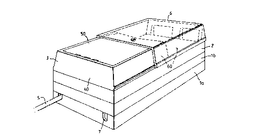
Referring to the drawings, Figure 1 shows a modular
unit comprising a base unit 1, a fibre organiser unit 2 and
a top unit 3. The base unit 1 has lower and upper parts la
and lb respectively, these together making up the full-height
base unit, but being separable in that the upper part lb of
the base unit can be removed to leave the lower part (half-
height base unit) la.
The modular unit is adapted to receive a blown fibre
cable 5, to the individual fibres of which customer
connections. can be made within the top unit 3, visible
~hrough a transparent sliding cover 6. The cable 5 has four
primary coated ~ibres housed within a single secondary
coating which is protected by an outer tube. Overall, the
Nodular unit has dimensions equivalent to those of a
CC conventional electrical double socket.
The functions o~ :.he various parts of the modular unit
are arranged so that the incoming cable 5 is dealt with as
rollows:
1. The incoming cable 5 is brought up to the half-
height base unit la.
2. I ns i de the hal f -hei ght bas a unit 1 a, the secondary
coated fibre is exposed from the outer tube of the cable 5,
and the end of the cable 5 and the secondary coated fibre are
clamped separately in the half-height base unit.
.C ?. A length of the secondary coated fibre is stored
in loops in the upper part lb of the base unit 1, the free
end of the secondary coat~:d fibre then being guided to the
_ybre organiser unit 2 where it is again clamped.
4. A length of each of the primary coated fibres,
which have been exposed by stripping the secondary coating
rom the end of the fibre, is stored in the lower part of the
'fibre organiser uni t ~, the free ends of the primary coated
'P
WO 92/22842 PGT/GB92/0109!~'
2i1~.57U - to -
fibres being fed into respective low friction tubes, such as
a polytetrafluoroethylene (ptfe? tubes.
5. The low Friction tubes, each carrying a primary
coated fibre, pass through a slot in the fibre organiser unit
2, from the lower to the upper side.
6. A length of each the low friction tubes is stored
in the upper side of the fibre organiser unit 2, and the free
ends of the tubing are led into the top unit 3.
7. The primary coated fibres and the low friction
tubes are all terminated at a connector within the top unit
3, which connector is coupled to a uniter mounted on an
appropriate panel to provide an optical "socket" which is
visible through, and accessible by means of, the transparent
sliding cover 6.
In this way, a blown fibre cable extends into the base
of the modular unit, and connection and disconnection can be
made to local equipment at the top of the unit by non-
experts.
In an alternative arrangement, instead of having
exposed primary coated fibres carried by low friction tubes,
factory "tails" might be used, each of these comprising a
termination having secondary coated fibre attached. In this
case, secondary coated fibres from the base unit 1 are
spliced directly to the "tails", using splice protectors
which are mounted in the lower part of the organiser unit 2.
The "tails" then extend through to the connector in the top
uni t 3 .
An installation procedure for installing a blown fibre
cable connection to a modular unit will now be described in
greater detail.
Referring to Figure 1, the modular unit to which a
blown fibre cable 5 is to be connected might already he
mounted, f or i ns tanc a by s c rews hol di ng the bas a uni t 1, i n
the office environment. To install the blown fibre cable 5,
~5 the top unit 3 and the fibre organiser unit 2 are removed,
exposing the open base unit 1.
'~'~'i0 92/22842 PCT/GB92/01096
- 11 -
Referring to Figures 2a, 2b, lla and llb, the half-
height base unit la is generally rectangular in plan view,
having two inlet slots 7 by means of which the blown fibre
cable 5 can be introduced. The outer tube of the blown fibre
cable 5 terminates as it enters the base unit la, being
retained at its inlet slot 7 by a star washer 4 (see Figure
10). In order to complete the installation as required,
about 2 to 3m of the secondary coated fibre 130 carried by
the cable 5 is left exposed beyond the end of the outer tube,
the end of that secondary coated fibre 130 being stripped to
expose about lm or more of each of the four primary coated
fibres, by known techniques.
Referring to Figure 10, the star washer 4 is
fabricated from a sheet of stainless spring steel about 0.3
or 0. 4mm thick. t has a lower part with an aperture 120,
and a substantiaiiy rectangular plate 121 extending upwards
therefrom, in use. The aperture 120 has inwardly-projecting
teeth 123. To install the end of the blown fibre cable 5 at
the inlet slot 7 cf the base unit '_, the star washer 4 is
~0 _irst mounted on the end of the cable, the washer being
dimensioned such that its teeth 123 grip the outer tube of
the cable firmly, this tube being somewhat resilient. As
shown in Figures 2a, 2b and lla, each slot 7 comprises a
primary channel 7a, which accommodates the blown fibre cable
25 ~, (including the outer tubing) and a cross slit ?b which
accommodates the sides of the star washer 4. Once mounted on
t'.:e end of the cable ~, the star washer 4 can be slid
downwards into the cross slit 7b, taking the end of the cable
with it and into position in the primary channel 7a.
30 As shown in Figures lla and llb, the blown fibre cable
5 is installed at a slot 7 by use of the co-operation of the
star washer 4 with the cross slit 7b. The star washer 4 has
the secondary funct_~n of closing the access slot 7 once the
cable 5 is installed. To demount the cable 5 from the base
~5 unit '_, the washer 4 can simply be removed from the cross
slit ,'b by pulling upwards on the rectangular plate portion
.21 of the washer.
WO 92/22842 PCT/GB92/0109~'
12 -
Referring to Figures 12 and 14, in an alternative
arrangement, instead of the star washer 4, a plastics
moulding 140 and crescent-shaped circlip 141 may be used.
The circlip 141 is mounted on the end of the cable 5, and
then fits into a slot in the plastics moulding 140. This has
an advantage in that the plastics moulding 140 may be
designed to "blank-off" unused entry holes to the base unit
1, prior to installation of the cable 5.
Referring to Figures 12a to 12d the plastics moulding
140 comprises a channel member 142 with a downwardly
depending circular plate 143 at one end and a pair of
downwardly-depending posts 144 at the other end. The
circular plate 143 is integral with the channel member 142,
being attached thereto at a semi-circular groove 145. Each
downwardly-depending post 144 has a slot 146 in the inwardly-
directed surface thereof, the slot extending from the bottom
surface of that post to part of the way up.
Referring to Figure 12b, the curved groove 145 has
a right-angle profile in cross-section, and has a depth only
slightly less than that of the end surface of the channel
member 142. To use the plastics moulding 140 to hold the end
of the blown fibre cable 5 in the base unit 1, the circular
plate 143 is broken or cut away at the groove 145, leaving a
curved opening dimensioned to seat over the outer tube of the
blown fibre cable.
Referring to Figures 12e and 12f, the crescent-shaped
circlip 141 is then mounted near the end of the blown fibre
cable 5. The circiip 141 has inner protrusions 147 which act
in the same manner as the teeth 123 of the star washer 4 and
"bite" on the cable end. The cable end is then mounted, from
below, into the channel member 142, the circlip 141 seating
in the slot 146, and the outer tube of the cable 5 seating in
the curved opening left by removal of the circular plate 143.
The plastics moulding 140 can then be mounted in the slot 7,
the channel member 142 actually seating in the slot 7 and the
posts 144 seating against the inner surface of the base unit
z~~~~~o
'"''alr0 92/22842 - 13 - PCT/GB92/01096
Referring to Figure 12g, the end of the cable 5 is
thus held against the curved, lower surface of the slot 7,
principally by the curved opening left by removal of the
circular plate 143. As a result, the slot 7 is entirely
closed by the channel member 142 and the cable 5. The cable
5 effectively passes through a fitted circular aperture, the
bottom half of which is defined by the bottom surface of the
slot 7, and the upper half of which is defined by the opening
made at the groove 14 by removal of the plate 143. Because
the posts 144 seat against the inside surface of the base
unit 1, pulling on the cable 5 is unlikely to pull the
moulding 140 or the cable out of the slot 7 unless the
moulding or the circlip 141 break.
Advantageously, as mentioned above, a plastics
moulding 140 can be used to "blank off", or seal off, a slot
7 in a base unit 1 in the absence of a cable 5. This is
simply done by mounting the plastics moulding 140 in the slot
7 without removal of the circular plate 143. The circular
plate 143, therefore, blocks off entry to the base unit 1 in
alace of the cable 5.
Referring to Figures 2a, 2b and 14, the secondary
coated optical fibre 130 extending from the end of the blown
fibre cable 5 into the base unit 1 is brought under a guide
160 and then around a first of two curved formers 8 and 9,
each of which is generally circular in plan view. This first
curved former 8 is provided with a resilient, high-friction
covering 10, being a neoprene (or rubber) band mounted about
its circumference. The outer surface of the Dormer 8 is
provided by a thin wall 180 of plastics material separated by
a gap 181 from the main part of the former 8, over a
substantial portion of its circumference.
At the side of this yirst curved former 8 which is
mast closely adj acent to the second curved former 9, clamping
means 11 are provided (not shown in Figure 14), this being a
caroming mechanism which can be rotated to push the thin wall
180 outwards and to bring the neoprene band 10 up against a
bearing surface 12 on the second curved former 9. By this
WO 92/22842 PCT/GB92/0109~'
21115'l0 - 14 -
means, the secondary coated fibre 130 can be clamped, without
damage, against axial tension which might be generated for
instance by the fibre' s own weight in a riser bringing the
blown fibre cable 5 to the modular unit.
Referring to Figures 7, 14 and 15 in more detail, the
caroming mechanism comprises a non-circular cylindrical
component 90 which seats in, and can be rotated within, a
substantially cylindrical cavity 91 at an edge of the first
curved former 8 adjacent to the second former 9. The
neoprene band 10 mounted around the first curved former 8
passes closely adjacent to the body 92 of the cylindrical
component 90, between flanges (or ears) 15, 16 and 17 on the
ends of the cylindrical component which protrude above, and
below, the thin wall 180.
Rotation of the cylindrical component 90 in its cavity
91 has a caroming action on the wail 180 and the neoprene band
10 in that it pushes the wall and the band outwards when
rotated in either direction from a rest position. Referring
particularly to Figures 7c and 15, in the rest position
(shown in Figure 15), the wall 180 lies adjacent to a very
shallow convex surface of the body 92 which approximates a
flat 13. When that body 92 is rotated in either direction,
the shoulders of the " flat" 13 provide caroming surfaces 14' ,
14" which act on the thin wall 180, flexing it towards the
second curved former 9. The fibre 130 lying against the band
10 can then be gripped between the band and the bearing
surface 12 on the second former 9, as indicated in Figure 14.
Because the shoulders of the "flat" 13 have different
radii of curvature, the amount by which the band 10 is moved
outwards by rotation oz the body 92 varies, depending on
which direction the bod~.~ 92 is rotated. This allows fibres
of different thicknesses, for instance either primary or
secondary coated fibre, ~o be clamped by the same mechanism.
As a whole, the substantially cylindrical component
90 comprises the body 92, with an incomplete flange 15 at one
end, and two ears 16 at the other end. It is rotated by
inserting a tool into a central slot 170. There is also
"..,~ 92/22842 ~ ~ ~ ~ 1 ~ ~ ~ P~./GB92/01096
- 15 -
provided a further pair of ears 17, formed by shaping of the
ends of the incomplete flange 15 so as to flank the missing
section thereof. As mentioned above, these two sets of ears
16 and 17, protrude above and below the thin wall 180,
offering supporting means to the fibre 130 lying around the
curved former 8, preventing it from sliding off that former
8 during loading and handling of the fibre organiser unit 2.
Referring to Figure 15, when mounted in the base unit
1 (not shown in the figure), the incomplete flange 15,
ZO together with the two ears 16, also provide retaining means
for the cylindrical component 90 in the base unit 1. The two
ears 16 at the lower end of the component 90 pass through
complementary enlargements 93 of the cavity 91, when the
component is being first installed. Once the component 90
.5 has been positioned in the cavity 91, it is rotated throuah
180° to bring it into i is rest position with the " flat" 1 3
facing the second curved former 9. In this position, the
ears 16 at the lower end of the component are retained under
the margin of the cavity 91 and under the thin wall 180,
20 holding the component 90 in place. In use, the two ears 16
also co-operate with stops (not shown) in the base unit 1 to
bring the component 90 into either of two pre-determined
rotational positions when turned by an operator. This allows
a preselected one of the two caroming surfaces 14' and 14" to
:.5 be brought accurately into operation on the band 10.
Referring to Figures ;a and 7c, the caroming surfaces
14' and 14" are provided as follows. The cross-section of
the body 92 of the cylindrical component 90 has a radius of
curvature wnich is primarily 7. 5mm. However, two adjoining
.0 parts of that cross section have radii of curvature of 8.35mm
and 28.Omm. The part having a radius of curvature of 28.Omm
creating the " flat" i3, the part having a radius c~ curvature
of 8.35mm creating a first bearing surface 14', and the
shoulder at the other end of the "flat" 13, where it reverts
~5 to the radius of curvature of 7.5mm, creates the second
bearing surface 14".
WO 92/22842 ~ ~ ~ ~ ~ ~ ~ - 16 - PCT/GB92/01096'
It should be noted that no part of the profile of the
body 92 has a radius of curvature of less than 4mm, even
where one radius of curvature blends into a different radius
of curvature. This prevents over bending of the fibre 130
clamped by means of the clamping mechanism 11 to a degree
damaging to the fibre.
Referring to Figure 14, the bearing surface 12 on the
second curved former 9 provides a resilient pad against which
the fibre 130 can be held. It is formed by a relatively
thin, shell section of plastics material which lies over a
cavity 80 in the second former 9 so that pressure on the
bearing surface 12 can depress it slightly.
Referring to Figures 2a, 2b and 14, once clamped by
the clamping mechanism 11, a length of the secondary coated
::fibre 130 can be stored in the full-height base unit 1, by
coiling in the space above the two curved formers 8 and 9.
Perhaps four or five turns of fibre might be so stored.
Bosses 210, primarily for use in mounting the base unit 1 for
instance as shown in Figure 13, and the guides 160, overhang
the space above the curved formers 8 and 9 and help to hold
the turns of fibre in place. However, during installation,
it is more convenient to have a length of the secondary
coated fibre 130 loose, so that the next stage of
installation, at the fibre organiser unit 2, can be carried
out with less constraint.
Referring to Figure 8a, the secondary coated fibre 130
i s brought from the bas a uni t 1 t o the unders i de o f the f i bre
organiser unit 2, where '_t is again held by a clamping
mechanism (not shown in full but only indicated by a cavity
labelled 101) of the same type as that described above with
reference to the base unit i. The fibre 130 is clamped at
the end of the secondary coating, leaning only the four
primary coated fibres 130' (only one of which is shown for
reasons of clarity) beyond. In this case, however, the
clamping mechanism 101 is mounted facing somewhat more
outwardly, so that it clamps the fibre 130 in a position
towards the perimeter of the organiser unit 2.
._._._...._- _-_T_.-_.__ _.___.___ ._ ..__..__T.. ....._._. ._._.... ..
2~.1~5?0
'~~'~O 92/22842 PCT/GB92/01096
- 17 -
Instead of being mounted on a first curved former,
about which the fibre is wound, and operating against a
second curved former, it is mounted behind a relatively
short, thin, plastics wall 104 which it pushes outwards
against a bearing surface 105 carried on a resilient, curved
wing 106 of plastics material, the shape of the bearing
surface 105 being complementary to that of the thin wall 104
against which this second clamping mechanism 101 acts.
Again, the clamping mechanism 101 acts indirectly, via the
thin wall 104, on a neoprene band 107, and it is this band
107 which actually grips the fibre, in use.
It will be realised that there is no necessity to be
able to support significant axial tension at this point in
the modular unit, and the fibre 130 does not, therefore, need
to lie against any significant length of the neoprene band
107 as it does against the equivalent band 10 in the base
unit 1.
Beyond the clamping point in the organiser unit 2, the
secondary coating is removed to leave only the four primary
coated fibres 130' exposed. (The secondary coating in this
embodiment is the secondary- coating normally provided in
clown fibre cable and techniques are known by means of which
_ ,. may be removed. )
Several loops of each primary coated fibre 130' will
be stored in this lower part of the fibre organiser unit 2.
However, before arranging the loops for storage, it is
convenient to pass the free end of each fibre 130' into the
respective capillary tube 1.0 which will carry it through a
slot to the upper part of the organiser unit 2.
Referring to Figure 3a and its insets, four ptfe
capill~~y tubes 110 (only one of which is shown for reasons
of cla~:ity), are provided, one for each fibre 130' . Each
tube 110 is secured by its end in a respective bore in an
elastomeric block 111. The block 111 is retained in a cavity
102 in the lower side of the organiser unit 2. To feed the
primary coated fibres 130' through to the upper part of the
unit 2, the block 111 is lifted from its cavity 102, and the
WO 92/22842 ~ O PCT/GB92/0109f~
- 18 -
free end of each fibre 130' simply fed into one of the bores
and therefore into the open end of a respective capillary
tube 110. This can be done without damage to the delicate
fibres 130' because of the non-frictional nature of ptfe.
The block 111 is then installed in its cavity 102, the
capillary tubes 110 being fed through a slot 103 to the upper
part of the organiser unit 2.
At this point of installation, a length of each
primary coated fibre 130' remains loose prior to storage
(shown in Figure 8a by a dotted line 130a). The flexible
wall 104 and the plastics wing 106 are both part of a
generally-circular former offset to an end of the organiser
unit 2. This leaves a significant space 109 towards the
other end of the unit 2. Several loops of each primary
coated fibre 130' can be stored in this lower part of the
unit 2 (as shown by a dotted line 130b in Figure 8a), by
installing it around the perimeter of the unit 2, taking in
both the generally circular former and the far end of the
space 109. Tabs 108 overhang the space 109 so as to hold the
stored loops of fibres in place.
Where a different type of fibre cable is being
installed, rather than the blown fibre cable described above,
the alternative arrangement of Figure 8b can be used.
common form of fibre cable has, as mentioned previously,
individual fibres each having both primary and secondary
coatings. In this case, the secondary coatings normally have
much less thickness. Accordingly, after the outer protective
tube is removed, the four secondary coated fibres are
overlined with a single replacement tube 130" which is used
to carry the secondary coated fibres to the clamping means 11
and the clamping mechanism 101. Also, instead of taking
primary coated fibres through to the upper part of the
organiser unit 2, using the capillary tubes 110, secondary
coated fibres can be brought through. In this case, a
respective factory tail 130c (only one shown) is spliced
directly to each secondary coated fibre 130 in the lower part
of the organiser tray 2. (A factory tail comprises a
~~'~!~J 92/22842 2 ~ 115 7 D p~/Gg92/01096
- 19 -
termination applied, in the fabrication plant, to a length of
secondary coated fibre, and can simply be spliced, in the
field, to a secondary coated fibre end.) Consequently, no
primary coated fibre need be exposed beyond the clamping
mechanism 101 or otherwise. Instead, the free fibre end of
each factory tail is fed through the slot 103, from the upper
to the lower part of the organiser tray 2, and spliced'to the
associated secondary coated fibre 130 held by the clamping
mechanism 101.
Spare loops of secondary coated fibre 130 are stored,
in this case, in the lower part of the organiser unit 2,
these loops being arranged substantially in the same way as
that in which the loops of primary coated fibre 130' are
stored in the embodiment described above with reference to
Figure 8a. In this embodiment, however, the splices, which
are protected by conventional splice protectors 115, are held
in place by a leaf spring device 113 whose ends are biased
outwards against the outer wall of the organiser unit 2.
Only one splice protector 115 is shown in Figure 8b, but
normally each fibre 130 would have a splice protector 115.
Each end of the leaf spring device 113 might then hold two
splice protectors in place, one above the other.
Referring to Figure 9, having passed through the slot
103 each capillary tube 110, or each fibre tail 130c, reaches
the upper part of the organiser unit 2. This is provided
with a generally circular former 116 which occupies about one
half of the unit 2, and with a fan-shaped guide structure 117
which lies adjacent to the other end of the unit. A full
loop of each of the four tubes 110 (or the fibre tails 130c)
lies around the circular former structure 116. The free end
of each tube 110 (or fibre tail 130c) is then wound to the
rear of the fan-shaped guide structure 117, approaching it
from one side or the other so that the tubes 110 (or fibre
tails 130c) are substantially symmetrically divided to
approach the guide structure from opposite sides. The guide
structure 117 provides four spaced curved exit channels 118
and each tube 110 (or fibre tail 130c) is brought into one of
WO 92/22842 PCT/GB92/0109~'
- 20 -
these, so as to leave the organiser unit 2 along a respective
upward path predisposed to co-operate with the positioning of
the terminations for fibre carried by a capillary tube 110
(or each fibre tail 130c) in the top unit 3.
It should be noted that the cylindrical component 90
is in place in Figure 9, providing the clamping mechanism 101
in use, in contrast to Figure 8 where only the receiving
cavity for the cylindrical component 90 is shown.
Referring to Figures 1, 3, 4, 5 and 13, the top unit
3 comprises a frame 40, a panel 60 in which the uniter or
uniters 150 may be mounted, a transparent, sliding cover 6,
and a transparent lid 50. The frame 40 sits on top of the
organiser tray 2 and is provided with ports 41 through which
customer connections can be made to the modular unit, and
with a rear section which may be closed or opened, depending
on the manner in which it will be used in practice.
The panel 60 (seen in Figure 5a) has four through
holes 62, through which customer connections can be made.
The panel 60 sits across the organiser unit 2, to close the
end thereof which will face the customer. The holes 62 are
provided in a substantially vertical section, at the upper
end of which is a flange 63. The clear plastics lid 50 (see
Figure 4b) is fixedly mounted, at least partly on the flange
63, to close the upper end of the frame 40 which lies away
from the main part of the panel 60. Thus, seen in plan view,
a first end of the modular unit is closed across its top by
the fixed clear plastics lid 50, the second end of the unit
being closed by the main, horizontal part of the panel 60.
These two ends are offset in a vertical direction, the gap
being closed by an upstanding portion of the panel 60, the
holes 62 being provided in this upstanding portion. The
sliding cover 6 Esee Fi.gu=e 4a) is then installed, at the
same level as the fixed lid 50, so that the modular unit as
a whole presents a substantially cuboidal exterior.
The last step in installing fibre from the fibre cable
5 is to bring the end of each capillary tube 110 (or fibre
tail 130c) from the fan-shaped guide structure 117 on the
~~IIS?0
"O 92/22842 PCT/GB92/01096
- 21 -
upper part of the organiser unit 2 to the respective uniters
150 under the clear plastics lid 50 of the top unit 3. Each
primary coated fibre carried by a capillary tube 110 can then
be connected in conventional fashion to a termination which
will be held by its respective uniter 150. Preferably, each
capillary tube 110 is also secured at the termination. where
a factory tail 130c has been used, the termination will
already be in place. It is then merely necessary to mount
the termination in its respective uniter 150.
To install or demount a connector to office equipment,
a customer slides back the plastics cover 6, passes a fibre
cable, with a connector 151 at the end thereof, through one
of the holes 41 of the frame 40, and mounts the connector at
a uniter 150 which has been provided in one of the holes 62
of the panel 60. Therefore, the customer has no access to
the stored primary or secondary coated fibre, or to the
stored flexible tubing 110, all of which is concealed and
protected within the body of the modular unit.
Different forms of uniter or connector might require
~0 different forms o~ holes 62 in the panel 60, and Ficrures 5a
and 5b show alternative versions of the panel 60 to
accommodate such ciLferent connectors or uniters.
Referring to Figure 13, the modular unit can be
installed in standard trunking, substantially in the same
manner as a 13 amp electrical socket. In this case, the
holes 41 in the frame 40 have been replaced by "L" shaped
slots 41'. This allows a customer to mount a connector at a
uniter, again provided in a respective one of the holes 62 of
the panel 60, before installing the fibre cable attached
'_0 thereto in position. Once the connector is mounted at the
uniter, the fibre cable can simply be pushed downwards and
along to the end of one of the "L" shaped slots 41'.
It should be noted that, in each form of the frame 40,
there is a continuous (or substantially continuous) shield
between the panel 60 and a user's eyes. In the arrangement
shown in Figures 3a and 3b, this shield is provided across
the tops of the holes 41. In the arrangement shown in Fiaure
WO 92/22842 PCT/GB92/0109f'
- 22 -
13, the shield is provided above the horizontal sections of
the "L" shaped slots 41'. Although the shield in the
arrangement shown in Figure 13 is discontinuous, it is, most
importantly, continuous at a position in line with any fibre
brought up to the rear of each uniter for connection to a
customer connector. This avoids a risk that the coherent
radiation carried by such a fibre might cause injury to the
customer if the output of the fibre is in the line of sight
of the customer. Thus the "L" shape design of the slots 41'
has two functions, one being the protection of the customer,
and the other being to retain the fibre more positively with
respect to the modular unit.
Referring to Figure 1, the stored loops of fibre in
the modular unit are used as follows:
I n the bas a uni t 1, the 1 oops are pri mari 1 y t o al l ow
separation of the fibre organiser tray 2 and the top unit 3
from the base unit 1 (which may be permanently installed in
situ). The base unit 1 may not be conveniently accessible
for maintenance, and so it is very useful that the organiser
2 0 uni t 2 and t op uni t 3 c a n be removed from the bas a uni t ? .
The loops stored in the base unit 1 will merely be uncoiled
in this situation, being re-coiled at reinstallation of the
organiser unit 2 and the top unit 3 on the base unit 1.
The fibre stored on the lower side of the organiser
tray 2, whether primary or secondary coated, is stored
primarily so that the splices, or terminations, can be broken
and remade. This process uses up fibre and it is often
important that a spare length of fibre should be available.
Referring to Figure 8a, it should be noted that stored
fibre can be used without changing the number of loops of
fibre stored. Whether stored as primary or secondary coated
fibre, the loops can be simply tightened up, shortening the
straight lengths of fibre which lie between the curves at
either end of the unit 2. Hence, a curve of fibre which lies
in the space 109 will lie in a different position within that
space when extra fibre has had to be used. This is indicated
for instance by the position of the dotted line 130b which
...._.-_-----_T~____ _ .........._....._..t.._.
'~1115'?0
~''~O 92/22842 PCT/GB92/01096
- 23 -
represents a curve of fybre after extra fibre has been used
and one or more loops of fibre tightened. There is some
considerable flexibility in this since each of several loops
lying in the space 109 can be tightened so that all of the
loops, instead of following the perimeter of the fibre
organiser unit 2, lie closer to the generally circular former
on which the clamping mechanism 101 is carried.
Where low friction capillary tubes 110 are provided to
take primary coated fibre to the top unit 3, the tightening
of the loops can be done simply by pulling the primary coated
fibres where they emerge from the capillary tubes 110.
On the upper side of the organiser unit 2, the
flexible tubes 110 can conveniently be stored in loops in
case these tubes 110 need to be shortened in making or re-
making connections to connectors or terminations. It may,
therefore, be important that there is additional flexible
tubing available. This may occur, for instance, where the
end of a flexible tube 110 is attached to a connector and,
instead of being demounted, is cut free in order to re-make
a connection.
Some slack in a capillary tube 110 allows the
associated fibre end to be inspected, and fibre end polishing
to be carried out, prior to a termination being made to a
fibre. However, another good reason storing either fibre
130' or capillary tubes 110 on the upper side of the
organiser unit 2 is to facilitate separation of that unit
from the top unit 3 for handling purposes.
The modular unit may be mounted in any of a plurality
of different situations, for instance being mounted on a rack
by means of a mounting system as disclosed in the
specification of our co-pending B~°' fish patent application
number 9106659.7 This allows a c venient access to, and
maintenance of, a unit. in the crowded conditions of a rack
s ys tem. -
Alternatively, the modular unit could be modified so
that it can be accommodated directly on a conduit box.
Instead of using cable entry via the slots 7 of the base unit
WO 92/22842 PCT/GB92/0109'
- 24 -
1, fibre entry might be directly through a slot 81 in the
base of the base unit 1, as shown in Figure 6.
Still referring to Figure 6, in another alternative
fibre entry system, adaptor accessories can be mounted to the
inlet slots 7 to provide access to a break-out portion 82 of
the full-height base unit 1, fibre entering through the
break-out portion, and then being guided to lie in either of
alternative guide channels 83 and 84. These options may be
i ncorporated i n the des i gn o f the bas a uni t 1, as s hown i n
Fi gure 6. Moreover, the bas a uni t 1 may be made i n a s i ngl a
moulding, rather than in the lower and upper units la and lb.
It might also be possible to amalgamate the organiser
and top units 2 and 3 into a single entity, particularly
where factory tails are used to bring fibres to the uniters
150. In this case, the loops of fibre, the splices and the
splice protectors 115 would be stored on the underside of the
amalgamated unit, and the fan-shaped guide structure 117, or
an equivalent, would be provided on the upper side, closely
adjacent to the upstanding panel carrying the holes 62 for
the uniters 150.