Note: Descriptions are shown in the official language in which they were submitted.
~111574
i
DEVICE AND METHOD FOR FILLING CORE-SHOOTING HEADS
WITH MOULD-CORE MATERIAL
The invention rela~es to a ~evice for filling
core-shooting head~ with mold-cors materials, the device
comprising an ou~let ~cmber or pipe for discharging ~he
mold-core material into the core-shooting head, and a
shutoff device for closing the outlet member. The
invention ~urther relates to a co~re~ron~i n~ method of
using the device under con~ideration.
In the foundry practice, core-shooting ~chinee
havR be~n known for many year~. For casting molded
component~, foundry corP~ or ~olds are mo~tly made in
eeparate parts, combined, and joined ~o one another to a
ca~ting mold. An es~ential pa~t o~ the core ~hooting
machines are the so-~alled core-shooting head~ with
ejector plates accommodating the shooting nozzles. It has
been common practice to fill the mold-core material, in
particular core sand, i.e. ~uartz ~nd already mixed or
coated with binders, into the core-shooting head~ u~der
con~i~eration, and thence to blow or shoot it under a very
high air pressure through the no~zles arranged in the
ejector pla~e into the re~pective molds.
In pra~tice, the core shooting head~ are ~ d
with core sand almost co~pletely, it further having ~een
co~mon praGtice to fill the core-~hooting heads re~ardles~
o~ the ~olume of core sand needed in the re~pective molds.
A~ a re~ult o~ ~illin~ the core-~hooting ~ead~ to an
alway~ considerable extent, the pre~~ure required for ~he
shooting is e~LL~.cly high. This pre~ure is normally
between four and six bar. This extremely high pre~ure i~
required in particular for the reason ~hat a con~iderable
CA 02111~74 1998-10-19
quantlty of core sand ls present between the shooting nozzles
and the source of lnflow of the compressed alr used for the
shootlng operatlon. To accelerate the sand partlcles through
the nozzle, lt ls necessary to blow the compressed alr through
the entlre volume of sand ln the core-shootlng head. Added to
thls ls an always uneven dlstrlbutlon of the core sand in the
core-shootlng heads. As a result, the pressure requlred for a
contlnuous shootlng operatlon has agaln to be very hlgh.
Core-shootlng under hlgh alr pressures whlch have so
far been absolutely necessary, is however extremely
problematlc ln practlce, slnce the sand exltlng from the
shootlng nozzles lmpacts always upon the walls of the mold to
be fllled, and has there an extremely abraslve effect. In
other words, the shootlng nozzles operate ln the meanlng of a
sand blastlng gun, so that the core sand exltlng under a hlgh
pressure damages the mold to be fllled successlvely, or
changes same ln lts geometry. A further dlsadvantage of core-
shootlng under hlgh alr pressures may be seen ln that already
when the core sand ls shot lnto the mold, the hlgh alr
pressures lead to compresslons of the core sand ln the reglon
of the ln~ectlon or shootlng. Consequently, ln partlcular ln
the case of compllcated geometrles, a form-locklng fllllng of
the mold ls lmpeded, or at least conslderable denslty
gradlents develop.
Furthermore, as a result of the hlgh alr pressures
and the resultant heavy lmpact of the sand upon the walls of
the respectlve mold, a blnder adherlng to the sand ls
downrlght blown off or separated, and last not least an uneven
dlstrlbutlon of sand and blnder develops as a result of the
denslty dlfferences between sand and blnder. Gases whlch are
llberated at hlgh temperatures from blnder concentratlons,
prevent agaln a unlform compresslon or the formatlon of a
flawless core.
7 ~
Finally, in the known core-shooting practice a serious problem lies in that,
regardless of the volumes of cores to be shot, the core-shooting heads are always filled to
the same level. As a consequence, it is necessary, even when the dimensions of the cores
to be shot are very small, to blast the compressed air required for the shooting through
the core sand deposit stored in the core-shooting head, or to accelerate the core sand
particles directly adjacent to the shooting nozzles. On the one hand, the large dimensions
of the core-shooting heads required for the shooting of large cores, and on the other hand
the considerable volume of core sand to be penetrated by the compressed air, however,
absolutely necessitate the high pressures previously represented to be extremely
disadvantageous .
It is therefore an advantage of the present invention to describe a device and a
method of filling core-shooting heads and mold-core materials, which allow for purposes
or reducing the compressed air pressures required for the shooting of cores, to fill the
core-shooting head in portions, and yet evenly, with a mold-core material.
In accordance with an aspect of the present invention, there is described a device
for filling core shooting head with mold core material comprising: a storage hopper for
retaining the mold core material; an outlet member connected to said hopper for
discharging the mold core material from the hopper and outlet member into the core
shooting head when said outlet member is inserted into the core shooting head; means
mounting said outlet member on a machine frame so as to be vertically adjustable and
permit said outlet member to be selectively positioned and secured in various vertical
positions within said core shooting head; and a shutoff device for selectively opening and
closing said outlet member.
Accordingly, the initially described device for filling core-shooting heads with
mold-core materials may be perfected and further developed such that for purposes of
immersing into the core-shooting head to be filled, the outlet member or pipe may be
mounted on a machine frame or the like for vertical movement and may be secured within
the range of its vertical mobility in any desired position.
In accordance with another aspect of the present invention there is described a
device for filling a core shooting head with mold core material comprising: a storage
hopper for ret~ining the mold core material; an outlet member defining a central vertical
axis and conn~cte~l to said hopper for discharging the mold core material from the hopper
and outlet member into the core shooting head when the outlet member is inserted into the
core shooting head; means mounting said outlet member on a vertically adjustable
machine frame so as to permit said outlet member to be selectively positioned and secured
in various vertical positions within the core shooting head, and so as to permit rotation of
said outlet member about a second vertical axis which is laterally offset from the central
vertical axis of said outlet member; drive means for selectively raising and lowering said
outlet member and for selectively rotating said outlet member about said second vertical
axis; and a shutoff device for selectively opening and closing said outlet member.
In accordance with the invention it has been recognized, first, that the core-
shooting head may be preferably filled as a function of the volume or the geometry of the
core to be shot. Furthermore, a quasi preliminary compression of the mold-core materials
to be accelerated by the shooting nozzles may be avoided in the core-shooting head in that
for filling the latter the outlet member immerses into the core-shooting head, and that thus
the mold-core material may be carefully filled into the core-shooting head. To this end,
the outlet member may be supported on a machine frame or an upright or the like for
vertical movement, and it may be secured in any desired position within the region of its
vertical mobility. In other words, "portions of mold-core material" can be supplied into
the core-shooting head in measured quantities, the metering being effected by the shutoff
device for closing the outlet member.
Thus, in accordance with the invention, it has been recognized that the core-
shooting head can be filled preferable as a function of the core to be shot. As a result of
the thus lesser filling capacity of the core-shooting head, it may be possible to reduce the
pressures required for the acceleration the mold-core or sand particles or for the shooting,
from a range of preferably six bar to less than three bar. Besides the low shooting
pressure, a mh~illlulll time for the passage of the mold-core material or sand may be
achieved. As a result of the lower shooting pressure both the molds to be filled and the
shooting nozzles can be effectively protected and, therefore, may have a longer service
life.
As regards the configuration of the outlet member, it is preferred when same is
made tubular. It is preferred that the storage hopper may be constructed substantially
funnel-shaped, so that when the outlet member directly adjoins the feed hopper, both
structural parts form together a kind of funnel with a filling tube. Within the scope of
such a configuration, the outlet member may be held by the storage hopper, so that it can
be vertically movable together with the storage hopper.
Likewise however, it would be conceivable to connect the outlet member via a
flexible hose or the like with the storage hopper. In such an event, the feed hopper could
be arranged stationarily, and preferably only the outlet member would be supported for
vertical movement.
:A
The vertical mobility of the outlet member and, possibly, of the storage hopper
could occur preferably via a lifting mechanism jointed to the machine frame and operating
between the machine frame and the outlet member or storage hopper. This lifting
mechanism could have at least one drive and, possibly, vertical guideways or guide
elements, so that the drive and the guideways are jointly responsible for the lifting motion
of the outlet member or the storage hopper. The drive itself could be designed and
constructed as a cylinder-piston arrangement, so that the provision of the latter would
already furnish a guideway, namely, the guidance of the piston in the cylinder.
It is preferable that for a loadable arrangement of the storage hopper or the outlet
member above the core-shooting head to be filled, preferably in the instance of a
considerably filled storage hopper, it is plerell~d that at least two or three drives or
cylinder-piston arrangements may be provided. Separate guideways may then become
unnecessary.
To be able to perform a controlled filling of the core-shooting head, i.e., in the
case of predetermined core dimensions to thus allow to fill a corresponding quantity of
core sand into the core-shooting head, the vertical movement of the outlet member and,
possibly, of the storage hopper may be adapted for detection by a displacement measuring
sensor. The latter may be a displacement measuring sensor which in one embodiment is
attached to the machine frame, and in another is operatively connected via a linkage with
the storage hopper or the outlet member. The arrangement may also be made in reversed
order. In an aspect of the present invention the displacement measuring sensor detects the
lifting movement of the piston of the piston-cylinder arrangement relative to the machine
frame. The displacement measuring sensor serving to detect the relative movement
between the outlet member and the machine frame and, thus, also relative to the core-
shooting head, may be noncont~cting in one preferred embodiment and as an alternative tothe above-described configuration. In this instance, the displacement me~mring sensor
could operate by induction, capacitance or the eddy-current principle. Likewise, a
photooptical detection would be conceivable. In a preferred embodiment, the displacement
measuring sensor could operate by means of ultrasound, and could be provided within the
cylinder-piston arrangement, for example, as an integral part thereof causing the stroke of
the outlet member, so that the movement of the piston may be detected directly.
With respect to a largely even distribution of the core sands inside the core-
shooting head, it is preferred that when the outlet member and, possibly, the storage
hopper may be rotatable about an axis of rotation substantially in horizontal direction.
This rotatability is preferably by 360~, i.e., the outlet member and, possibly, the storage
hopper can be pivoted or rotated endlessly about an axis of rotation. The axis of rotation
extends substantially parallel to the outlet member outside thereof.
Furthermore, it is an aspect of the present invention the outlet member and the
axis of rotation may be coordinated with the core-shooting head or its inlet opening, so as
to permit the 360~ rotation within the core-shooting head, and without contacting its
walls. Consequently, it may be possible to evenly distribute more or less the mold-core
material or core sand to be shot or blown through the shooting nozzles by, for example,
rotating the outlet member several times, so that the bulk density of the core sand forming
in the core-shooting head may be without, or exhibits only insignificant density gradients.
As regards the rotatability of the outlet member or storage hopper about the axis of
rotation it is further preferable to provide to this end preferably an electric drive motor.
This latter could likewise be a so-called senomotor which may be able to realize the
A movements very accurately within a millimeter and with any desired change of direction.
"- -
With regard to construction, the drive motor could be operatively connected via
suitable mounting means and a turntable with the outlet member or the storage hopper.
Thus, for example, the motor could engage via corresponding means in the outer portion
of the turntable. Accordingly, the inner portion of the turntable would be fixedly
conn~octe~l with a mounting disk or the like.
In particular, from the viewpoint of saving floor space, the drive motor for
rotating the outlet member and, possibly, the storage hopper, as well as the cylinder-
piston arrangement for raising and lowering the outlet member or the storage hopper
could be integrated to one structural assembly. In other words, the drive motor for
rotating the outlet member could be arranged, for example, on the lower end of the
cylinder-piston arrangement, i.e. it could be stationarily mounted on the exiting piston of
the cylinder-piston arrangement, or its extension.
With respect to an exactly definable quantity of core sands to be filled into the
core-shooting head, it would be preferable to arrange the shutoff device at the discharge
end of the outlet member. Such a configuration could allow to fill or store the core sands
from the lower end of the outlet member up to the upper end of the storage hopper. Upon
opening the shutoff device, and after immersion into the core-shooting head, could the
core sands enter into the latter, and up to the depth of immersion of the outer end of the
outlet member.
For a particularly simple and effective configuration of the shutoff device, same
may be constructed as a shutter which may be adapted for rotation to the front of the
discharge end of the outlet member and for sealing same at least to a great extent. The
shutter lies thus approximately in a plane formed by the bottom edge of the outlet
,., ~
~ member, and can be rotated in this plane toward the discharge opening of the outlet
member or away from the region of the discharge opening. In this arrangement, the outlet
member and the shutter are dimensioned such that when the outlet member is immersed
into the core-shooting head, the shutter can be rotated away, so that the discharge end
may be at least largely unobstructed or opened.
The axis of rotation of the shutter extends substantially parallel to the outlet
member outside thereof. Within the scope of a preferable development of the teaching in
accordance with the invention, the axis of rotation of the outlet member and the axis of
rotation of the shutter may be substantially identical with respect to geometry, so that the
shutter smoothing or leveling the filled core sand performs the same rotating motion as
the outlet member, with this motion resulting in a smoothing or leveling of the core sand
filled into the core-shooting head in almost the same plane.
For the rotating motion of the shutter, the latter may be secured in any desired
rotated positions over the entire range of rotation. This means that it may be possible to
adjust the extent of opening of the outlet member, thereby influencing as a whole the
filling speed on the one hand and the quantity of the filling on the other.
With respect to the actuation of the shutter, it is preferred when same may be
rotated by means of a cylinder-piston arrangement. For the tr~n~mi~sion of force or the
conversion of the linear movement of the cylinder-piston arrangement into a rotating or
swing motion of the shutter, the cylinder-piston arrangement may act upon the shutter via
a rocking lever and a guide rod rotatable by the rocking lever.
To prevent core sands in the storage hopper from adhering to less steep walls
thereof as a result of adhesion, a vibration device may be preferably associated to the feed
hopper, which causes the walls of the feed hopper to vibrate. When the outlet member is
fixedly connected to the storage hopper, the vibratory motion will naturally also propagate
~ . .
to the outlet member, so that the core sands as a whole may be effortless transferred into
the core-shooting head. Just because of the vibration device, it is however preferable to
arrange between the storage hopper or outlet member and the machine frame, preferably
between the storage hopper or outlet member and the turntable, at least one swing element
for preventing vibrations from propagating to the machine frame. A vibration device
could, for example, be an electric motor with an eccentric swivel or mass component.
In another aspect of the present invention, there is described a method of filling
core-shooting heads with mold core material comprising the steps of providing a device
for filling core shooting heads with mold core material comprising a storage hopper for
ret~ining the mold core material, an outlet member associated with said hopper for
discharging the mold core material into the core shooting head and a rotatable shutter
which closes an outlet end of said outlet member; filling said storage hopper with the
mold core material while said shutter is closed; positioning the outlet member above the
core shooting head; immersing said outlet member into the core shooting head wherein
said outlet member is immersed a predetermined distance depending upon a desired filling
height; opening said shutter so as to at least partially fill the core shooting head to said
predetermined filling height; closing said outlet member by rotating said shutter; and
retracting said outlet member to an idle position.
In addition it is preferable that the outlet member and, in the event of a direct
connection between the outlet member and storage hopper, also the storage hopper may be
moved to their idle position, i.e. to their upper position. This position ensures that the
core-shooting head may be moved below the outlet member. In its idle position, the
storage hopper may be filled with core sand, with the shutter being closed. Consequently,
it is possible to fill on the one hand the outlet member, and on the other hand the feed
1 1
hopper up to its upper edge in accordance with the filling density of the core sand.
Subsequently, the core shooting head may be positioned below the outlet member. At this
point, it should be noted that the positioning of the core-shooting head below the outlet
member may also occur at an earlier time, for example, already prior to filling the storage
hopper with core sand. It is only preferable to make sure that adequate space may be
available below the outlet member for positioning the core-shooting head.
Preferably, the outlet member may be immersed into the core-shooting head, the
depth of immersion being predetermined by the preferred filling of the core-shooting head
with core sand. This filling depends again on the volume and the realizable density of the
core to be shot In its immersed condition, the outlet member may be in its operating
position. In the following, the shutter may be opened at least in part for partially filling
the core-shooting head to a predetermined height. As a result of the immersion depth, the
filling occurs substantially up to the lower edge of the outlet member. If need arises, the
outlet member may be closed by the shutter, the latter thereby leveling the filled core
sand to some degree. Within the scope of the totally possible rotation or pivoting by 360~,
the outlet member may be moved to a further operating position with a predetermined
depth of immersion, so that likewise the region adjacent to the previously filled position
within the core-shooting head may be further filled. Thus, in a further position, the outlet
member may be reopened by the shutter, and the filling operation may repeat itself as
desired in dirrelellt positionings of the outlet member until the desired filling height is
reached. Likewise, it may be possible to pull the outlet member gradually upward during
the filling of the core-shooting head, so as to permit to realize a predeterminable filling
height, with as a whole, a lowest possible drop height of the core sand particles. Thus,
,i ,;
A~ there results within the core-shooting head only a certain bulk density of the core sands,
lla
but by no means a compacting corresponding to the knock density or even a greater
density.
Furthermore, the filled core sand may be leveled both by the rotating motion of
the shutter and the swing motion of the outlet member itself. This allows to realize an
accurate filling volume. A repeated rotation or filling makes it possible to realize any
desired filling heights.
Finally, once the core-shooting head may be adequately filled, the outlet member
may be closed by the shutter and removed from the core-shooting head to its idle position.
Various possibilities exist to perfect and further develop the teaching of the present
invention in advantageous marmer. To this end reference may be made to the claims
subsequent to the invention as disclosed on the one hand, and to the following description
of an embodiment of the invention with reference to the drawing. In conjunction with the
description of the plerell~d embodiment of the invention with reference to the drawing,
also generally plerelled embodiments and further developments of the teaching are
described. In the drawing:
Figure 1 is a schematic side view, cut, of an embodiment of a device in
accordance with the invention for filling core-shooting heads with core sands, the device
being shown in its operating position; and
.''~
CA 02111~74 1998-10-19
.
Flgure 2 ls a schematlc sectlonal vlew of the sub~ect matter
of clalm 1 along llne II-II.
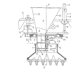
Illustrated ln Flgure 1 ls a sectlonal schematlc
vlew of a device for fllllng core-shootlng heads 1 wlth mold-
core materlals, the latter belng core sand ln the here
selected embodlment. Essentlal component parts of the devlce
lnclude a storage hopper 3 for core sand 2, an outlet member
or outlet plpe 4 for dlscharglng core sand 2 lnto core-
shootlng head 1, and a shutoff devlce 5 for closlng outlet
member 4.
In accordance wlth the inventlon, for purposes of
lmmerslng lnto core-shootlng head 1 for fllllng, the outlet
member 4 ls mounted for vertlcal movement on a machlne frame
6, and can be secured steplessly ln any deslred posltlon
wlthln the range of lts vertlcal moblllty.
Flgure 1 shows ln comblnatlon wlth Flgure 2 that
outlet member 4 ls deslgned and constructed substantlally
tubular. The storage hopper 3 ls made funnel-shaped. As ls
further clearly shown ln Flgure 1, outlet member 4 dlrectly
ad~olns storage hopper 3, so that outlet member 4 ls held by
storage hopper 3 and can be moved vertlcally together wlth the
storage hopper 3.
The vertlcal moblllty of outlet member 4 or of
outlet member 4 together wlth storage hopper 3 occurs vla a
llftlng mechanlsm 7 ~olnted to machlne frame 6 and operatlve
between machlne frame 6 and outlet member 4 or storage hopper
3. In the here selected embodlment, llftlng mechanlsm 7
comprlses two drlves whlch serve slmultaneously as vertlcal
guldeways. More speclflcally, they are cyllnder-plston
arrangements 8.
The vertlcal movement of outlet member 4 or
storage hopper 3 can be detected by means of a noncontactlng
dlsplacement measurlng sensor 9. Thls dlsplacement
measurlng sensor 9 detects the llftlng motlon
13 2 ~ 7 4
'~_
o~ a piston 10 of cylinder piston arrange~ent 8 relative
to maa~ine ~rame 6. In the here selected ~mho~; ment,
di~placement ~ea~uring ~ensor 9 operates by meana o~
ultrasound.
As can be noted from ~oth Figure 1 and Figure 2,
outlet ~ember ~ and ~orage hopper 3 a~e endles~ly
rotatable a~ a whole about an axis o~ rotation 11, i.e. by
360~ and more, in horlzontal direction. The axis of
ro~atian 11 extends in thi~ arrangement parallel to outlet
member ~ out~ide th~r~of. A~ can be noted from Figure 2,
the outlet member 4 ~nd axis of rotation 11 are adapted to
~o~e sho~ting ~ead ~ or its inlet opening lZ 80 as to
permit without any problem the 360~ rotation within ~ore-
shooting head l.
AS regard~ the rotating movement of outlet
~em~er ~ or s~orage hopper 3 it is essenti~l that outle~
member 4 be rotated ~ogether with storage hopper 3 by
means of an electric drive motor 13. The la~ter i~ only
s~her~tically indica~ed in Figure l. The drive motor 13
i~ op~rati~ely connected via corre~ro~ g mounting mean~
1~ and a turntabl~ S~ with out~et member 4 or atorage
hopper 3. As is furt~er ~hown in Figure 1, drive motor 13
for rotating outlet member S or storage hopper 3 an~
cylinder-piston arr~ngement 8 for raiE~ng and lowering
ou~let mem~er ~ are integrated to one ~tructural assembly.
Fuxther clearly ~hown in Figure 1 is that
shutoff device S is arra~ged at di~charge e~d l~ of outlet
~ember ~. ~ore 6peci~ically, shutoff device 5 i~ designed
and const~ucted as a shutter 17 adapted ~or rotation to
the ~ront of di~;ch~rge end 16 of outlet member { and ~or
largely ~ealing same. ~utlet member 4 and ~hutter l~, aE:
illu~trated in ~igure 2, are dimension~d such a~ to permit
shutter 17 to rotate away, when outlet member 4 i~
immersed into core-~hootirlg }~ead 1, so t~at outlet end 1
i~ entirely uncovered.
7 4
14
~ oth Fig~re 1 and Figure 2 show that shutter 17
i~ rotatable about an axi~ of rotation extP~; n~
sub~tantially parallel to outlet member ~. Both Figures
show that the axi~ of rotation 11 of outlet member ~ and
th~ axis of rotation 18 o~ shutte~ 17 are geometrically
about identi~al. Furtherm~re, it i~ es~ential that over
the entire range of rotation ~huttsr 17 ~an be secured in
any desired rotated positions, t~e illu~tration selected
in Figurc 2 indicating two rotated position~.
~ ig further indicated in Figure 1, ~hutter 17
1~ rotated by means of a cylinder-piston arrangement 19.
Th~s cylinder-piston arrange~ent lg is operati~ely
connected vla a rocking lever 20 and a guide rod 21 wi~
shutter 17. Thus, it is pos~ible ~o convert the linear
movement of cylinder-piston arra~ge~ent 19 -- via rocking
lever 20 and guide rod ~1 -- into ~ rotatlng movement of
~hutter 17.
: As i~ still furthe~ shown in Figure 1,
a~o~i Ated to storage hopper 3 is a vibration device ~3
for vibrating a wall 22 of stor~ge hopper 3. In order to
avoid that ~he vibration serving to shake the core sand
into ou~let member ~ propagates to machine frame 6, a
~wing element 2~ in~alled between outle~ ~ember ~ or
storgage hopper 3 and turntable lS i~ provided for
p~ Ling ~ibration~ ~rom propagating to machine frame 6.
Finally, a~ thi~ point, it should merely bc
mentioned that for an exact determination of the ~uantity
to ~e fllled into core-~ho~ting head 1, ~torage hopper 3
and outlet mem~er ~ may be pro~ided with a weighing
device. The la~ter would determine in a particularly
advantage~u~ manner the weight difference between the
e~pty ~torage hopper or empty o~tlet ~ember and the
storage hopper or ~utlet member filled with core sand.
~ikewi~e, it would ~e pnssi~le to monitor, via a weight
~ 5 7 4
loss, the ~illing the core-~hooting h~ad, i~ being
pos~iPle to pred~tenmine in e~ortless manner the desired
~illin~ le~el via the weight and with known den~ity or
bul~ density.
As re~ards ~he method o~ the pre~ent invention,
re~erence may be made ~o the de~cription in the general
portion of the epeci~ication.
In summary, it ~hould be ~rh~sized that the
gist o~ the pre~ent invention -- accurate adjust3ent of
the ~illing quantity of mold-core material ~equired for
making a c~re with an a~Lvximately even distribution of
the mold-core material in~ide the ~ul~ _hooting head --
may be realized al~o with other ~illing devices or core-
shooting heads. The foreqoing emhn~ nt merely described
~y way of exa~ple ~erves only for an under~n~;ng of the
tç~hi~g of t~e pre~ent invention, ~ut is not limited
thereto.