Language selection

Search

Patent 2111666 Summary

Third-party information liability

Some of the information on this Web page has been provided by external sources. The Government of Canada is not responsible for the accuracy, reliability or currency of the information supplied by external sources. Users wishing to rely upon this information should consult directly with the source of the information. Content provided by external sources is not subject to official languages, privacy and accessibility requirements.

Claims and Abstract availability

Any discrepancies in the text and image of the Claims and Abstract are due to differing posting times. Text of the Claims and Abstract are posted:

  • At the time the application is open to public inspection;
  • At the time of issue of the patent (grant).
(12) Patent: (11) CA 2111666
(54) English Title: FIRECODE ACCESS PANEL
(54) French Title: PANNEAU D'ACCES INCENDIE
Status: Expired and beyond the Period of Reversal
Bibliographic Data
(51) International Patent Classification (IPC):
  • E04B 2/00 (2006.01)
  • E04F 19/08 (2006.01)
  • E06B 5/16 (2006.01)
(72) Inventors :
  • LANGENHORST, CHRISTOPH (Germany)
(73) Owners :
  • OPUS PATENT-UND KNOW-HOW VERWERTUNGSGESELLSCHAFT MBH
(71) Applicants :
  • OPUS PATENT-UND KNOW-HOW VERWERTUNGSGESELLSCHAFT MBH (Germany)
(74) Agent: BORDEN LADNER GERVAIS LLP
(74) Associate agent:
(45) Issued: 1997-11-25
(22) Filed Date: 1993-12-16
(41) Open to Public Inspection: 1994-07-01
Examination requested: 1994-05-06
Availability of licence: N/A
Dedicated to the Public: N/A
(25) Language of filing: English

Patent Cooperation Treaty (PCT): No

(30) Application Priority Data:
Application No. Country/Territory Date
P 42 44 578.7-25 (Germany) 1992-12-31

Abstracts

English Abstract


The panel assembly has a panel generally fitting in a hole and having an outer
periphery running generally parallel to the inner periphery of the hole. Respective
geometrically similar inner and outer annular frames on the inner and outer peripheries
have confronting outer faces forming an annular gap around the panel between the inner
and outer frames. One of the frames has an inner face forming an annular compartment
extending around the respective periphery. This one frame is formed with an array of
throughgoing openings which extend between the respective inner and outer faces and
connect the compartment with the gap. The compartment is substantially closed except
at the openings. An annular body of heat-swellable mate rial is provided in the
compartment so that on heating of the material it swells and exits the compartment
through the openings to fill the gap.


French Abstract

La présente invention vise un panneau constitué d'un élément inséré dans une ouverture et dont le bord extérieur est généralement parallèle au bord intérieur de l'ouverture. Le bord extérieur de l'élément et le bord intérieur de l'ouverture sont respectivement garnis d'un cadre de géométrie similaire, entre les faces externes desquels un vide annulaire est aménagé. La face interne de l'un des cadres forme un compartiment annulaire sur toute la périphérie. Ce cadre comporte un ensemble d'orifices qui en traversent les deux faces et relient le compartiment au vide annulaire. Mis à part les orifices, le compartiment est essentiellement fermé. Un cordon de matériau gonflable à la chaleur est inséré dans le compartiment; lorsque ce matériau est chauffé, il gonfle et se répand dans le vide annulaire par les orifices.

Claims

Note: Claims are shown in the official language in which they were submitted.

C L A I M S
1. A firecode access-panel assembly for use in a wall
having a throughgoing access hole with an inner periphery, a
firecode access-panel assembly comprising:
a panel generally fitting in the hole, having an outer
periphery running generally parallel to the inner periphery of
the hole;
geometrically similar first and second annular frames
respectively extending along one of the peripheries of the hole
and the panel and having spaced part opposite faces forming an
annular gap therebetween around the panel, the first frame having
and annular L-section element an inner leg representing one of
the gap defining faces and extending generally perpendicular to
the wall and panel surfaces and an outer leg parallel to an outer
surface of the wall and panel, and an annular Z-section element
having an outer web lying against the respective outer surface
underneath the outer leg of the first frame, an inner web
extending generally parallel to the surfaces and outwardly
butting against an inner face of the inner leg the first frame,
and an intermediate web bridging the inner and outer webs and
extending generally parallel to the inner face, the inner face
forming with the element an annular compartment extending around
the respective periphery;
the inner leg of the first frame being formed with an
array of throughgoing openings extending between respective inner
and outer faces of the inner leg, the compartment being
substantially closed except at the openings;
and an annular body of heat-swellable material in the
compartment, whereby on heating of the material said annular body
swells and exits the compartment through the openings to fill the
gap.
2. The firecode access-panel assembly defined in claim 1
wherein the Z-shaped section of the one frame is a stiff annular
element set in the panel and the body of heat-swellable material

is wholly contained between the annular element and the L-shaped
section.
3. The firecode access-panel assembly defined in claim 1
wherein the throughgoing openings are in a regular array
extending around the respective periphery.
4. The firecode access-panel assembly defined in claim 1,
further comprising latching means actuatable by heat to lock the
panel in the hole.
5. The firecode access-panel assembly defined in claim 4
wherein the latching means includes:
a spring mounted on a predetermined one of the frames
and having a leg displaceable between a normal position extending
from the frame it is mounted on across the other frame to block
same and a retracted position wholly out of the way of the other
frame,
a holder mounted on the predetermined one of the frames
and retaining the spring thereon, and
a heat fusible body in the holder normally retaining
the spring leg in the retracted position.
6. The firecode access-panel assembly defined in claim 5
wherein the other frame is provided with a strike forming a
pocket open toward the guide and receiving the spring leg in the
normal position.

Description

Note: Descriptions are shown in the official language in which they were submitted.


~ ~ .L L ~j ~3
- FIRECODE ACCESS PANEL
Field of the Invention
The present invention relates to an access panel. More particularly this invention
collc~ s a firecode access-panel assembly.
5 ~n ~ d of the I~
An access opening in a firecode wall, which term is here intended to cover a side ~;
wall, floor, or ceiling, must be con~ ,1cd of fireproof material and in such a manner
that it does not open or let fire pass in case of a fire on one side of the wall. Thus it is
known to mount on the outside edge of the door or on the inside edge of the opening a
10 strip of ro~llablc mRt~nRl for instance a specially f rmnlRt~od poly~lylcne or
polyu,clll~le, that will swell and fill any gap between the outer pel;phcl~y of the panel
and the inner p~,fi~ ,ly of the hole. In case of a fire this material will ~ ,lefole
cLrc~;livt;ly block passage of anything past the gap around the panel.
The main disadvantage with this allall~ClllClll iS that the strip is relatively
5 exposed. Even when it is set in a groove of a frame lining the inside of the opening or
surrounding the panel edge, it can be .~ ed relatively easily. Moisture can get to it
with ease, and in the normal course of using the access panel it can be 11~m~eed to the
point where it no longer functions as ~ creating a code violation.
Objects of the I~
~ ,.. .
It is Ill~,lerulc an object of the present invention to provide an improved firecode
access-panel assembly.
Another object is the plovi~;on of such an hlll)lovcd firecode access-panel
assembly which O~ ;OIIl~,S the above-given di~d~ ges, that is which will surely seal
the opening around the door but where the foamable strip will not be liable to damage
during normal use of the panel.
~ .
..

" ~
Summary of the Invention
The panel assembly according to the invention has a panel generally fitting in ahole and having an outer periphery running generally parallel to the inner periphery of
the hole. Respective geoll.cllically similar inner and outer armular frames on the inner
5 and outer p~ ,h~.;çs have cullrlulllillg outer faces forming an annular gap around the
panel between the inner and outer frames. One of the frames has an inner face forming
an armular cclll~ llent ~YtPnrling around the l~e-;liv~ p~ hely. This one frame is
formed with an array of throughgoing openings col~le~ g the c.~ lll with theannular gap and the collllJalllllclll is ~ b~ y closed except at the op~;llhl~,~. An
0 annular body of heat-swellable material is provided in the co~ ,.ll so that on
heating of the material it swells and exits the cûlll~llllcnts through the openings to fill
the gap.
Thus with this arrangement the inner p~fi~ y of the opening and the outer
peli~h~,~y of the panel are both provided with and prolr~ d by a stiff rugged frame,
15 normally of metal. The swellable mass is wholly c~ d in the culll~llll~ll behind
one of the frames so that it is c~ l l ly out of harm's way. Nonetheless when heated
the mass will swell and erupt out of the holes to effectively fill the gap and seal around
the panel.
The panel and wall in accold~lce with this invention have generally coplanar
20 outer surfaces and the one frame is L-shaped wvith an inner leg defining the l~e-;live
inner and outer faces and eytpn~ing generally perp~nrli~ r to the wall and panelsurfaces and an outer leg lying flatly on the respective outer surface. The one frame
further cc",ll,- ;~es a stiff annular element set in the panel and defining the COIll~ llenL
The body is wholly colll~iilcd between the annular element and the one frame. More
25 specifically the annular element is generally of Z-section having an outer web Iying
against the l~s~ccliv~ outer surface ~ the outer leg of the one frame, an inner
web .-1~ "l;"g generally parallel to the surfaces and outwardly butting against the inner
face of the one frame, and an i~,t~..",r~ lt; web r.lr.l.1il~g ~ ely of the sl-rf~-çc,
bridging the inner and outer webs, and .oYt~ntling generally parallel to the inner face.
30 This very ~L~,liv~ly protects the normally fairly soft and fragile strip forming the
foamable body.

3 - ~
The holes are in a regular array ~l~t~nrling around the respective periphery. They
can be circular in shape or slots. The assembly is also provided according to the
invention with a latch actuatable by heat to lock the panel in the hole. This latch
includes a spring mounted on a pre~ . ",i,-~d one of the frames and having a legdisplaceable between a normal position r~ g from the frame it is mounted on ~;
across the other frame to block same and a retracted position wholly out of the way of
the other frame, a holder mounted on the l,le~ ",i"Pd one of the frames and retaining
the spring thereon, and a heat-fusible body in the holder normally retaining the spring
leg in the retracted position. Thus when the heat-fusible body melts, the leg springs out
to block the panel in the closed position. The other frame is provided with a strike
forming a pocket open toward the guide and receiving the spring leg in the normal
position.
Brief De~ of the Drawing
The above and other objects, features, and advantages will become more readily
apparent from the following description, l~r~ ,ncc being made to the accon~allyillg
drawing in which:
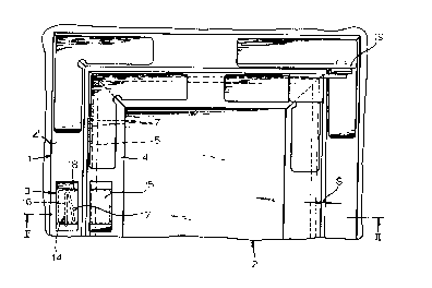
Fig. 1 is a plan view of the firecode access-panel assembly according to the
invention;
Fig. 2 is a section taken along line II--II of Fig. l; and
Figs. 3 and 4 are detail views taken in the direction of lt~i~C~,livt~ arrows III and
IV of Fig. 2.
Speciffc D~l r~
As seen in Figs. 1 and 2 a fireproof wall l is formed with an opening in which is
po~ition~d a fireproof panel 2, the opening and panel being of geometrically similar
rectangular shape. The rectangular outer p~fi~h~,ly of the panel 2 and the innerp~,l~h~,l y of the door opening are provided with le~e.;live L-section frames 4 and 4'
having lt;~C~,livt~ outer flanges l l and l l' lying on the coplanar outer faces of the panel
2 and wall l and inner flanges 6 and 6' r.~ g pel~elldi~;ular to these surfaces and
. ~ . .. ~ ' . , , ' ' . ,
' .~ :. : .

4 ~ i 'J '~ S
- defining an annular space or gap S. Hinges 19 allow the panel 2 to pivot like a door
and a latch 3 is provided to hold it shut as described below in greater detail.
Un~ th one of the frames, here under the inner frame 4, is a Z-section bar 8
having an outer flange or web 10 Iying under the outer frame flange 11, an inner flange
5 or web 12 ~yten~ing parallel thereto and butting outwardly on an inside face of the inner
flange 6, and a middle web 13 bridging the webs 11 and 12 and PYt~nrling parallel to
but spaced inwardly from the lc~e~;live inner flange 6 to forrn therewith an annular
co~ ~l,llent 9 co~ g a body 5 of a heat-foamable resin. The flange 6 is formed as
seen in Fig. 3 with a uniform array of through-going circular holes 7, although slots
lo would be equally functional, through which the resin body 5 can extrude when heated to
fill the space S.
The latch 3 collll~l;ses a holder 18 on the outer frame 4' and colll~ lg a spring
14 having as shown in Fig. 4 a leg 16 that can extend across the space S to lodge in a
pocket formed by a strike or keeper 15 provided on the frame 4. A fusible pin 17 in the
holder 18 normally keeps the spring 14 folded as shown in Fig. 2, with its arm 16
retained in the holder 14. When heated, this pin 17 melts to release the spring arm 16
and allow it to pop out of the housing 18, thereby locking the door shut.
The foamable mass 5 is held in the COIlll)a~ ll 9 and is there very well
protected from damage. The total flow cross section of the holes 7 is ~ y less
2 o than the area of the cOlll~ llclll 9 to ensure this protection, but since the mass 5 is
liquefied as it exits through the holes 7 this presents no l~illL~Ice to effective operation.
.: : -

Representative Drawing
A single figure which represents the drawing illustrating the invention.
Administrative Status

2024-08-01:As part of the Next Generation Patents (NGP) transition, the Canadian Patents Database (CPD) now contains a more detailed Event History, which replicates the Event Log of our new back-office solution.

Please note that "Inactive:" events refers to events no longer in use in our new back-office solution.

For a clearer understanding of the status of the application/patent presented on this page, the site Disclaimer , as well as the definitions for Patent , Event History , Maintenance Fee  and Payment History  should be consulted.

Event History

Description Date
Inactive: IPC from MCD 2006-03-11
Time Limit for Reversal Expired 2004-12-16
Letter Sent 2003-12-16
Inactive: Entity size changed 2002-11-20
Letter Sent 2000-01-21
Inactive: Office letter 1999-09-08
Inactive: Office letter 1999-04-27
Grant by Issuance 1997-11-25
Inactive: Adhoc Request Documented 1997-09-19
Inactive: Application prosecuted on TS as of Log entry date 1997-09-19
Inactive: Status info is complete as of Log entry date 1997-09-19
Pre-grant 1997-07-08
Notice of Allowance is Issued 1997-04-22
Application Published (Open to Public Inspection) 1994-07-01
All Requirements for Examination Determined Compliant 1994-05-06
Request for Examination Requirements Determined Compliant 1994-05-06

Abandonment History

There is no abandonment history.

Fee History

Fee Type Anniversary Year Due Date Paid Date
Final fee - small 1997-07-08
MF (patent, 4th anniv.) - small 1997-12-16 1997-12-04
MF (patent, 5th anniv.) - small 1998-12-16 1998-10-21
Registration of a document 1998-12-14
MF (patent, 6th anniv.) - small 1999-12-16 1999-11-22
MF (patent, 7th anniv.) - small 2000-12-18 2000-08-29
MF (patent, 8th anniv.) - small 2001-12-17 2001-06-28
MF (patent, 9th anniv.) - standard 2002-12-16 2002-11-12
Owners on Record

Note: Records showing the ownership history in alphabetical order.

Current Owners on Record
OPUS PATENT-UND KNOW-HOW VERWERTUNGSGESELLSCHAFT MBH
Past Owners on Record
CHRISTOPH LANGENHORST
Past Owners that do not appear in the "Owners on Record" listing will appear in other documentation within the application.
Documents

To view selected files, please enter reCAPTCHA code :


To view images, click a link in the Document Description column. To download the documents, select one or more checkboxes in the first column and then click the "Download Selected in PDF format (Zip Archive)" or the "Download Selected as Single PDF" button.

List of published and non-published patent-specific documents on the CPD .

If you have any difficulty accessing content, you can call the Client Service Centre at 1-866-997-1936 or send them an e-mail at CIPO Client Service Centre.


Document
Description 
Date
(yyyy-mm-dd) 
Number of pages   Size of Image (KB) 
Cover Page 1995-04-08 1 53
Claims 1995-04-08 2 91
Abstract 1995-04-08 1 32
Description 1995-04-08 4 188
Drawings 1995-04-08 2 96
Cover Page 1997-11-24 1 55
Claims 1997-04-22 2 76
Representative drawing 1997-11-24 1 12
Courtesy - Certificate of registration (related document(s)) 2000-01-21 1 115
Maintenance Fee Notice 2004-02-10 1 175
Correspondence 1999-04-27 1 12
Correspondence 1999-09-08 1 7
Correspondence 1999-11-18 1 7
Fees 1996-10-11 1 51
Fees 1995-12-07 1 39
Courtesy - Office Letter 1994-08-26 1 43
Prosecution correspondence 1994-05-06 1 25
PCT Correspondence 1997-07-08 1 34
PCT Correspondence 1999-05-26 1 24
PCT Correspondence 1999-10-15 1 40
PCT Correspondence 1999-12-10 1 27
Prosecution correspondence 1996-12-13 5 177
Examiner Requisition 1996-06-14 2 68
Prosecution correspondence 1994-10-13 4 140