Sélection de la langue

Search

Sommaire du brevet 2111666 

Énoncé de désistement de responsabilité concernant l'information provenant de tiers

Une partie des informations de ce site Web a été fournie par des sources externes. Le gouvernement du Canada n'assume aucune responsabilité concernant la précision, l'actualité ou la fiabilité des informations fournies par les sources externes. Les utilisateurs qui désirent employer cette information devraient consulter directement la source des informations. Le contenu fourni par les sources externes n'est pas assujetti aux exigences sur les langues officielles, la protection des renseignements personnels et l'accessibilité.

Disponibilité de l'Abrégé et des Revendications

L'apparition de différences dans le texte et l'image des Revendications et de l'Abrégé dépend du moment auquel le document est publié. Les textes des Revendications et de l'Abrégé sont affichés :

  • lorsque la demande peut être examinée par le public;
  • lorsque le brevet est émis (délivrance).
(12) Brevet: (11) CA 2111666
(54) Titre français: PANNEAU D'ACCES INCENDIE
(54) Titre anglais: FIRECODE ACCESS PANEL
Statut: Périmé et au-delà du délai pour l’annulation
Données bibliographiques
(51) Classification internationale des brevets (CIB):
  • E04B 2/00 (2006.01)
  • E04F 19/08 (2006.01)
  • E06B 5/16 (2006.01)
(72) Inventeurs :
  • LANGENHORST, CHRISTOPH (Allemagne)
(73) Titulaires :
  • OPUS PATENT-UND KNOW-HOW VERWERTUNGSGESELLSCHAFT MBH
(71) Demandeurs :
  • OPUS PATENT-UND KNOW-HOW VERWERTUNGSGESELLSCHAFT MBH (Allemagne)
(74) Agent: BORDEN LADNER GERVAIS LLP
(74) Co-agent:
(45) Délivré: 1997-11-25
(22) Date de dépôt: 1993-12-16
(41) Mise à la disponibilité du public: 1994-07-01
Requête d'examen: 1994-05-06
Licence disponible: S.O.
Cédé au domaine public: S.O.
(25) Langue des documents déposés: Anglais

Traité de coopération en matière de brevets (PCT): Non

(30) Données de priorité de la demande:
Numéro de la demande Pays / territoire Date
P 42 44 578.7-25 (Allemagne) 1992-12-31

Abrégés

Abrégé français

La présente invention vise un panneau constitué d'un élément inséré dans une ouverture et dont le bord extérieur est généralement parallèle au bord intérieur de l'ouverture. Le bord extérieur de l'élément et le bord intérieur de l'ouverture sont respectivement garnis d'un cadre de géométrie similaire, entre les faces externes desquels un vide annulaire est aménagé. La face interne de l'un des cadres forme un compartiment annulaire sur toute la périphérie. Ce cadre comporte un ensemble d'orifices qui en traversent les deux faces et relient le compartiment au vide annulaire. Mis à part les orifices, le compartiment est essentiellement fermé. Un cordon de matériau gonflable à la chaleur est inséré dans le compartiment; lorsque ce matériau est chauffé, il gonfle et se répand dans le vide annulaire par les orifices.


Abrégé anglais


The panel assembly has a panel generally fitting in a hole and having an outer
periphery running generally parallel to the inner periphery of the hole. Respective
geometrically similar inner and outer annular frames on the inner and outer peripheries
have confronting outer faces forming an annular gap around the panel between the inner
and outer frames. One of the frames has an inner face forming an annular compartment
extending around the respective periphery. This one frame is formed with an array of
throughgoing openings which extend between the respective inner and outer faces and
connect the compartment with the gap. The compartment is substantially closed except
at the openings. An annular body of heat-swellable mate rial is provided in the
compartment so that on heating of the material it swells and exits the compartment
through the openings to fill the gap.

Revendications

Note : Les revendications sont présentées dans la langue officielle dans laquelle elles ont été soumises.


C L A I M S
1. A firecode access-panel assembly for use in a wall
having a throughgoing access hole with an inner periphery, a
firecode access-panel assembly comprising:
a panel generally fitting in the hole, having an outer
periphery running generally parallel to the inner periphery of
the hole;
geometrically similar first and second annular frames
respectively extending along one of the peripheries of the hole
and the panel and having spaced part opposite faces forming an
annular gap therebetween around the panel, the first frame having
and annular L-section element an inner leg representing one of
the gap defining faces and extending generally perpendicular to
the wall and panel surfaces and an outer leg parallel to an outer
surface of the wall and panel, and an annular Z-section element
having an outer web lying against the respective outer surface
underneath the outer leg of the first frame, an inner web
extending generally parallel to the surfaces and outwardly
butting against an inner face of the inner leg the first frame,
and an intermediate web bridging the inner and outer webs and
extending generally parallel to the inner face, the inner face
forming with the element an annular compartment extending around
the respective periphery;
the inner leg of the first frame being formed with an
array of throughgoing openings extending between respective inner
and outer faces of the inner leg, the compartment being
substantially closed except at the openings;
and an annular body of heat-swellable material in the
compartment, whereby on heating of the material said annular body
swells and exits the compartment through the openings to fill the
gap.
2. The firecode access-panel assembly defined in claim 1
wherein the Z-shaped section of the one frame is a stiff annular
element set in the panel and the body of heat-swellable material

is wholly contained between the annular element and the L-shaped
section.
3. The firecode access-panel assembly defined in claim 1
wherein the throughgoing openings are in a regular array
extending around the respective periphery.
4. The firecode access-panel assembly defined in claim 1,
further comprising latching means actuatable by heat to lock the
panel in the hole.
5. The firecode access-panel assembly defined in claim 4
wherein the latching means includes:
a spring mounted on a predetermined one of the frames
and having a leg displaceable between a normal position extending
from the frame it is mounted on across the other frame to block
same and a retracted position wholly out of the way of the other
frame,
a holder mounted on the predetermined one of the frames
and retaining the spring thereon, and
a heat fusible body in the holder normally retaining
the spring leg in the retracted position.
6. The firecode access-panel assembly defined in claim 5
wherein the other frame is provided with a strike forming a
pocket open toward the guide and receiving the spring leg in the
normal position.

Description

Note : Les descriptions sont présentées dans la langue officielle dans laquelle elles ont été soumises.

~ ~ .L L ~j ~3
- FIRECODE ACCESS PANEL
Field of the Invention
The present invention relates to an access panel. More particularly this invention
collc~ s a firecode access-panel assembly.
5 ~n ~ d of the I~
An access opening in a firecode wall, which term is here intended to cover a side ~;
wall, floor, or ceiling, must be con~ ,1cd of fireproof material and in such a manner
that it does not open or let fire pass in case of a fire on one side of the wall. Thus it is
known to mount on the outside edge of the door or on the inside edge of the opening a
10 strip of ro~llablc mRt~nRl for instance a specially f rmnlRt~od poly~lylcne or
polyu,clll~le, that will swell and fill any gap between the outer pel;phcl~y of the panel
and the inner p~,fi~ ,ly of the hole. In case of a fire this material will ~ ,lefole
cLrc~;livt;ly block passage of anything past the gap around the panel.
The main disadvantage with this allall~ClllClll iS that the strip is relatively
5 exposed. Even when it is set in a groove of a frame lining the inside of the opening or
surrounding the panel edge, it can be .~ ed relatively easily. Moisture can get to it
with ease, and in the normal course of using the access panel it can be 11~m~eed to the
point where it no longer functions as ~ creating a code violation.
Objects of the I~
~ ,.. .
It is Ill~,lerulc an object of the present invention to provide an improved firecode
access-panel assembly.
Another object is the plovi~;on of such an hlll)lovcd firecode access-panel
assembly which O~ ;OIIl~,S the above-given di~d~ ges, that is which will surely seal
the opening around the door but where the foamable strip will not be liable to damage
during normal use of the panel.
~ .
..

" ~
Summary of the Invention
The panel assembly according to the invention has a panel generally fitting in ahole and having an outer periphery running generally parallel to the inner periphery of
the hole. Respective geoll.cllically similar inner and outer armular frames on the inner
5 and outer p~ ,h~.;çs have cullrlulllillg outer faces forming an annular gap around the
panel between the inner and outer frames. One of the frames has an inner face forming
an armular cclll~ llent ~YtPnrling around the l~e-;liv~ p~ hely. This one frame is
formed with an array of throughgoing openings col~le~ g the c.~ lll with theannular gap and the collllJalllllclll is ~ b~ y closed except at the op~;llhl~,~. An
0 annular body of heat-swellable material is provided in the co~ ,.ll so that on
heating of the material it swells and exits the cûlll~llllcnts through the openings to fill
the gap.
Thus with this arrangement the inner p~fi~ y of the opening and the outer
peli~h~,~y of the panel are both provided with and prolr~ d by a stiff rugged frame,
15 normally of metal. The swellable mass is wholly c~ d in the culll~llll~ll behind
one of the frames so that it is c~ l l ly out of harm's way. Nonetheless when heated
the mass will swell and erupt out of the holes to effectively fill the gap and seal around
the panel.
The panel and wall in accold~lce with this invention have generally coplanar
20 outer surfaces and the one frame is L-shaped wvith an inner leg defining the l~e-;live
inner and outer faces and eytpn~ing generally perp~nrli~ r to the wall and panelsurfaces and an outer leg lying flatly on the respective outer surface. The one frame
further cc",ll,- ;~es a stiff annular element set in the panel and defining the COIll~ llenL
The body is wholly colll~iilcd between the annular element and the one frame. More
25 specifically the annular element is generally of Z-section having an outer web Iying
against the l~s~ccliv~ outer surface ~ the outer leg of the one frame, an inner
web .-1~ "l;"g generally parallel to the surfaces and outwardly butting against the inner
face of the one frame, and an i~,t~..",r~ lt; web r.lr.l.1il~g ~ ely of the sl-rf~-çc,
bridging the inner and outer webs, and .oYt~ntling generally parallel to the inner face.
30 This very ~L~,liv~ly protects the normally fairly soft and fragile strip forming the
foamable body.

3 - ~
The holes are in a regular array ~l~t~nrling around the respective periphery. They
can be circular in shape or slots. The assembly is also provided according to the
invention with a latch actuatable by heat to lock the panel in the hole. This latch
includes a spring mounted on a pre~ . ",i,-~d one of the frames and having a legdisplaceable between a normal position r~ g from the frame it is mounted on ~;
across the other frame to block same and a retracted position wholly out of the way of
the other frame, a holder mounted on the l,le~ ",i"Pd one of the frames and retaining
the spring thereon, and a heat-fusible body in the holder normally retaining the spring
leg in the retracted position. Thus when the heat-fusible body melts, the leg springs out
to block the panel in the closed position. The other frame is provided with a strike
forming a pocket open toward the guide and receiving the spring leg in the normal
position.
Brief De~ of the Drawing
The above and other objects, features, and advantages will become more readily
apparent from the following description, l~r~ ,ncc being made to the accon~allyillg
drawing in which:
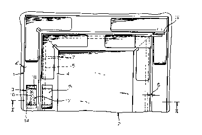
Fig. 1 is a plan view of the firecode access-panel assembly according to the
invention;
Fig. 2 is a section taken along line II--II of Fig. l; and
Figs. 3 and 4 are detail views taken in the direction of lt~i~C~,livt~ arrows III and
IV of Fig. 2.
Speciffc D~l r~
As seen in Figs. 1 and 2 a fireproof wall l is formed with an opening in which is
po~ition~d a fireproof panel 2, the opening and panel being of geometrically similar
rectangular shape. The rectangular outer p~fi~h~,ly of the panel 2 and the innerp~,l~h~,l y of the door opening are provided with le~e.;live L-section frames 4 and 4'
having lt;~C~,livt~ outer flanges l l and l l' lying on the coplanar outer faces of the panel
2 and wall l and inner flanges 6 and 6' r.~ g pel~elldi~;ular to these surfaces and
. ~ . .. ~ ' . , , ' ' . ,
' .~ :. : .

4 ~ i 'J '~ S
- defining an annular space or gap S. Hinges 19 allow the panel 2 to pivot like a door
and a latch 3 is provided to hold it shut as described below in greater detail.
Un~ th one of the frames, here under the inner frame 4, is a Z-section bar 8
having an outer flange or web 10 Iying under the outer frame flange 11, an inner flange
5 or web 12 ~yten~ing parallel thereto and butting outwardly on an inside face of the inner
flange 6, and a middle web 13 bridging the webs 11 and 12 and PYt~nrling parallel to
but spaced inwardly from the lc~e~;live inner flange 6 to forrn therewith an annular
co~ ~l,llent 9 co~ g a body 5 of a heat-foamable resin. The flange 6 is formed as
seen in Fig. 3 with a uniform array of through-going circular holes 7, although slots
lo would be equally functional, through which the resin body 5 can extrude when heated to
fill the space S.
The latch 3 collll~l;ses a holder 18 on the outer frame 4' and colll~ lg a spring
14 having as shown in Fig. 4 a leg 16 that can extend across the space S to lodge in a
pocket formed by a strike or keeper 15 provided on the frame 4. A fusible pin 17 in the
holder 18 normally keeps the spring 14 folded as shown in Fig. 2, with its arm 16
retained in the holder 14. When heated, this pin 17 melts to release the spring arm 16
and allow it to pop out of the housing 18, thereby locking the door shut.
The foamable mass 5 is held in the COIlll)a~ ll 9 and is there very well
protected from damage. The total flow cross section of the holes 7 is ~ y less
2 o than the area of the cOlll~ llclll 9 to ensure this protection, but since the mass 5 is
liquefied as it exits through the holes 7 this presents no l~illL~Ice to effective operation.
.: : -

Dessin représentatif
Une figure unique qui représente un dessin illustrant l'invention.
États administratifs

2024-08-01 : Dans le cadre de la transition vers les Brevets de nouvelle génération (BNG), la base de données sur les brevets canadiens (BDBC) contient désormais un Historique d'événement plus détaillé, qui reproduit le Journal des événements de notre nouvelle solution interne.

Veuillez noter que les événements débutant par « Inactive : » se réfèrent à des événements qui ne sont plus utilisés dans notre nouvelle solution interne.

Pour une meilleure compréhension de l'état de la demande ou brevet qui figure sur cette page, la rubrique Mise en garde , et les descriptions de Brevet , Historique d'événement , Taxes périodiques et Historique des paiements devraient être consultées.

Historique d'événement

Description Date
Inactive : CIB de MCD 2006-03-11
Le délai pour l'annulation est expiré 2004-12-16
Lettre envoyée 2003-12-16
Inactive : Grandeur de l'entité changée 2002-11-20
Lettre envoyée 2000-01-21
Inactive : Lettre officielle 1999-09-08
Inactive : Lettre officielle 1999-04-27
Accordé par délivrance 1997-11-25
Inactive : Demande ad hoc documentée 1997-09-19
Inactive : Dem. traitée sur TS dès date d'ent. journal 1997-09-19
Inactive : Renseign. sur l'état - Complets dès date d'ent. journ. 1997-09-19
Préoctroi 1997-07-08
Un avis d'acceptation est envoyé 1997-04-22
Demande publiée (accessible au public) 1994-07-01
Toutes les exigences pour l'examen - jugée conforme 1994-05-06
Exigences pour une requête d'examen - jugée conforme 1994-05-06

Historique d'abandonnement

Il n'y a pas d'historique d'abandonnement

Historique des taxes

Type de taxes Anniversaire Échéance Date payée
Taxe finale - petite 1997-07-08
TM (brevet, 4e anniv.) - petite 1997-12-16 1997-12-04
TM (brevet, 5e anniv.) - petite 1998-12-16 1998-10-21
Enregistrement d'un document 1998-12-14
TM (brevet, 6e anniv.) - petite 1999-12-16 1999-11-22
TM (brevet, 7e anniv.) - petite 2000-12-18 2000-08-29
TM (brevet, 8e anniv.) - petite 2001-12-17 2001-06-28
TM (brevet, 9e anniv.) - générale 2002-12-16 2002-11-12
Titulaires au dossier

Les titulaires actuels et antérieures au dossier sont affichés en ordre alphabétique.

Titulaires actuels au dossier
OPUS PATENT-UND KNOW-HOW VERWERTUNGSGESELLSCHAFT MBH
Titulaires antérieures au dossier
CHRISTOPH LANGENHORST
Les propriétaires antérieurs qui ne figurent pas dans la liste des « Propriétaires au dossier » apparaîtront dans d'autres documents au dossier.
Documents

Pour visionner les fichiers sélectionnés, entrer le code reCAPTCHA :


Pour visualiser une image, cliquer sur un lien dans la colonne description du document. Pour télécharger l'image (les images), cliquer l'une ou plusieurs cases à cocher dans la première colonne et ensuite cliquer sur le bouton "Télécharger sélection en format PDF (archive Zip)" ou le bouton "Télécharger sélection (en un fichier PDF fusionné)".

Liste des documents de brevet publiés et non publiés sur la BDBC .

Si vous avez des difficultés à accéder au contenu, veuillez communiquer avec le Centre de services à la clientèle au 1-866-997-1936, ou envoyer un courriel au Centre de service à la clientèle de l'OPIC.


Description du
Document 
Date
(aaaa-mm-jj) 
Nombre de pages   Taille de l'image (Ko) 
Page couverture 1995-04-08 1 53
Revendications 1995-04-08 2 91
Abrégé 1995-04-08 1 32
Description 1995-04-08 4 188
Dessins 1995-04-08 2 96
Page couverture 1997-11-24 1 55
Revendications 1997-04-22 2 76
Dessin représentatif 1997-11-24 1 12
Courtoisie - Certificat d'enregistrement (document(s) connexe(s)) 2000-01-21 1 115
Avis concernant la taxe de maintien 2004-02-10 1 175
Correspondance 1999-04-27 1 12
Correspondance 1999-09-08 1 7
Correspondance 1999-11-18 1 7
Taxes 1996-10-11 1 51
Taxes 1995-12-07 1 39
Courtoisie - Lettre du bureau 1994-08-26 1 43
Correspondance de la poursuite 1994-05-06 1 25
Correspondance reliée au PCT 1997-07-08 1 34
Correspondance reliée au PCT 1999-05-26 1 24
Correspondance reliée au PCT 1999-10-15 1 40
Correspondance reliée au PCT 1999-12-10 1 27
Correspondance de la poursuite 1996-12-13 5 177
Demande de l'examinateur 1996-06-14 2 68
Correspondance de la poursuite 1994-10-13 4 140