Note: Descriptions are shown in the official language in which they were submitted.
-1- 211175~
FASTENER-DRIVING TOOL WITH IMPROVED, ADJUSTABLE, TOOL-ACTUATING
STRUCTURES
Technical Field of the Invention
This invention pertains to a fastener-driving tool, which may
be pneumatically powered or combustion-powered and which has
improvements enabling the tool to be readily adjusted to adjust the
depth of penetration of fasteners driven by the tool. The
fasteners may be nails or staples.
Background of the Invention
Fastener-driving tools, which may be pneumatically powered or
combustion-powered, are used widely in building construction. Such
pneumatically powered tools are exemplified in Golsch U.S. Patent
No. 4,932,480. Such combustion-powered tools are exemplified in
Nikolich U.S. Patent Re. 32,452 and in Nikolich Canadian Patent
Application File No. 2,088,837 filed February 4, 1993.
Typically, such a pneumatically powered or combustion-powered
tool includes a housing structure, a nosepiece extending from the
housing structure, a primary actuating structure and a secondary
actuating structure. Both of these actuating structures are
mounted movably to the nosepiece. The primary actuating structure
is movable between a tool-disabling position relative to the
housing structure and a tool-enabling position relative thereto and
is biased to the tool-disabling position. Typically, the fastener-
driving tool also includes a trigger, which must be manually
actuated to operate the tool once the tool has been enabled.
The primary actuating structure is arranged to enable the
tool when such structure is moved to the tool-
enabling position and to disable the tool when such
~11175~
structure is moved from the tool-enabling position. The
F~con~ry actuating structure is arranged to move the
primary actuating structure to the tool-enabling
position when the ~e~on~ry actuating structure i~
pressed firmly against a workpiece.
For various applications, it is known to drive
the fasteners to different depths of penetration so that
their heads are flush with a workpiece, so that their
heads remain st~ g above the workpiece, or so that
their heads are countersunk into the wor~piece. ~n~
known heretofore for adjusting the secondary actuating
structure of such a tool so as to adjust the depths of
penetration of fasteners driven by the tool into a
workpiece have not been entirely satisfactory.
Summary of the Invention
This invention provides improvements in a fastener-
driving tool comprising a housing structure, which
defines an axis, and a nosepiece extending axially from
the housing structure, along with a primary actuating
structure and a ~econ~y actuating structure. The
primary actuating structure is movable between a tool-
enabling position relative to the housing structure and
a tool-disabling position relative thereto and is biased
to the tool-disabling position. The primary actuating
structure enables the tool when the primary actuating
structure is moved to the tool-enabling position and
disables the tool when the primary actuating structure
i8 moved away from the tool-enabling position. The
seco~ry actuating structure is mounted movably to the
nosepiece and is adapted to be firmly preC~e~ against a
workpiece.
An intermediate structure is is mounted movably to
the nosepiece. Ihe intermediate structure is engaged
with the primary actuating structure. A bolt has a head
and a shank with a threaded portion, which is threaded
21~l~75~
- 3 -
ad~ustably into an axial socket in one of the
intermediate and secon~Ary actuating structures. The
intermediate and secon~ ry actuating structures are
mounted so as to be relatively movable over a limited
range of relative movement and are biased ~o as to hold
the bolt head against a flange exten~ing from the other
of the intermediate and 6eco~ry actuating structures.
Preferably, the bolt head has flat surfaces
parallel to the axis and the flange has an axially
exten~ing tab, which is disposed to engage a selected
one of the flat surfaces to prevent bolt rotation when
the bolt head is held by the flange with the selected
æurface facing the tab. The flange and the bolt head
are separable by relative movement of the intermediate
and secondary actuating structures so as to permit the
bolt head to clear the tab and the bolt to be then
rotated. The secondary actuating structure also may
have a raised formation disposed to engage another of
the flat surfaces when the bolt head is held by the
flange with the selected surface facing the tab.
If the flats define a regular polygon, such as a
regular hexagon, the bolt may be a conventional bolt
having a polygonal head. If such a bolt is used, the
bolt may be adjusted by regular, angular intervals (e.g.
60- intervals if such flats define a regular hexagon) so
as to enable the depths of penetration of fasteners
driven by the tool to be adjusted by regular, precise
intervals.
Preferably, the intermediate and secon~ry
actuating structures are biased by a coiled spring
disposed around the bolt shank. Preferably, moreover,
the intermediate element has the axial Fo~ket and the
secondary actuating element has the flange with the
axially exten~ing tab. In a preferred embodiment, in
which the flange therewith is a lower flange, the
211175~
- 4 -
~econ~ry actuating element also has an upper flange
spaced ~YiAlly from the flange with such tab, ~nd the
coiled spring is disposed between the bolt head and the
upper flange.
These and other objects, features, and ~dvantages
of this invention are evident from the following
description of a preferred embodiment of this invention
with reference to the accompanying drawings.
Brief Description of the Drawin~s
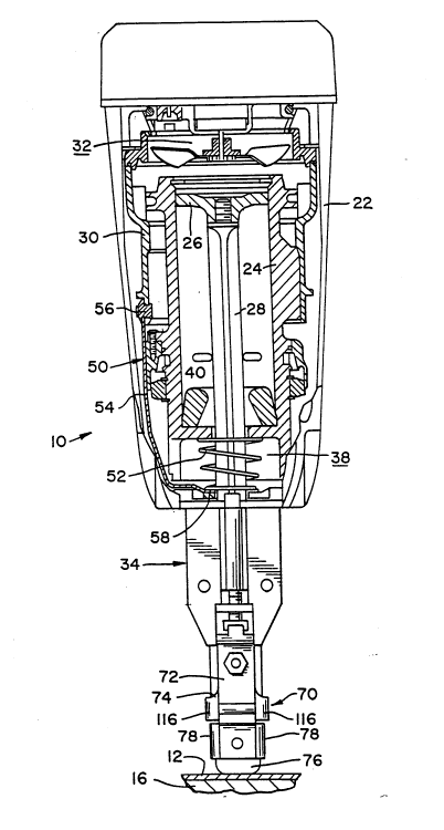
Figure 1 is an elevational view taken partly in
cross-section and showing a combustion-powered,
fastener-driving tool embodying this invention. A
workpiece and a substrate are shown fragmentarily.
Figures 2 and 3 are enlarged, perspective views of
certain actuating and related structures apart from
other structures of the tool shown in Figure 1,
respectively in positions for tool operation and in
positions for tool adjustment.
Figure 4 is an exploded, perspective view of
certain actuating and related structures shown in
Figures 2 and 3, apart from other structures of the
tool.
Figure 5 is a view similar to Figures 2 and 3 but
taken to show one mode of ~ ccembly of certain
actuating structures from another structure of the tool.
~etailed Description of Preferred Fmhodiment
As shown in Figure 1, this invention may be
embodied in a combustion-powered, fastener-driving tool
10, which is shown being used to drive fasteners (not
shown) through a wor~piece 14 into an underlying
substrate 16. Altho~lqh it is convenient to illustrate
the tool 10 in a vertical orientation, as in Figure 1,
the tool 10 may be also used if rotated from the
vertical orientation. Herein, "upper", "lower~,
"innern, "outern, and other directional terms refer to
21 1 1 152
- 5 -
the tool 10 in the vertical orientation and are not
intended to limit this invention to any particular
orientation.
The tool 10 comprises a housing ~tructure 22,
within which a cylinder body 24 i~ mounted fixedly. The
cylinder body 24 defines a tool axis. A piston 26 is
mounted operatively in the cylinder body 24. The piston
26 is arranged to drive a driving blade 28 ext~n~;ng
axially from the cylinder body 24. A valve sleeve 30 is
10 ` mounted in axially movable relation to the cylinder body
24. The cylinder body 24 and the valve sleeve 30 define
a combustion chamber 32. The valve sleeve 30 is
moveable axially, alo~g the cylinder body 24, 80 as to
open and close a combustion chamber 32. A nosepiece 34
is mounted to the housing structure 22, in axially
spaced relation to the cylinder body 24. A lower
chamber 38 is defined between the cylinder body 24 and
the nosepiece 34. A resilient bumper 40 is disposed
within the cylinder body 24 for arresting the piston 26.
A primary actuating structure 50 is provided for
closing the combustion ~hAmhe~ 32 when a secon~Ary
actuating structure to be later described is pressed
firmly against the workpiece 12. The structure 50
includes plural (e.g. four) arms 54 (one shown)
connected to the valve sleeve 30 by fasteners 56 (one
shown) so as to be con30intly movable with the valve
sleeve 30. The structure arms 54 are con~Pcted to each
other and to the secon~Ary actuating structure 52 by an
annular member 58 disposed within the lower chamber 38
and across the tool axis. The structure arms 54 are
~haped so as to extend outwardly from the lower chamber
38 and upwardly along the cylinder body 24.
A coiled spring 52, which is disposed within the
lower chamber 38, is compressible between the cylinder
body 24 and the annular member 58 of the primary
21 1 1752
- 6 -
actuating structure 50, so as to bias the valve sleeve
30, via the structure S0, to a tool-disabling position,
in which the combustion chamber 32 i8 opened. The lower
chamber 38 provides axial clearance, e.g. about one inch
of axial clearance, to permit a limited range o axial
movement of the structure arms 54 and the annular member
58 relative to the cylinder body 24, the nosepiece 34,
and the housing structure 22 between the tool-disabling
position and a tool-enabling position, in which the
combustion chamber 32 is closed. The tool 10 is
disabled when the combustion chamber 32 is not closed.
The tool 10 comprised a manually actuatable trigger (not
shown) which must be also actuated, after the combustion
ch~h~r 32 has been closed to enable the tool 10, so as
to operate the tool 10 for driving a fastener, such as a
nail or a staple.
As described in the prPce~ing three paragraphs,
except for the manner in which the structure 50 is moved
to the tool-enabling position, the tool 10 is similar to
combustion-powered, staple-driving tools available
commercially from ITW Paslode, su~ra, under its IMPULSE
trademark. Thus, except as illustrated and described
herein, other structural and functional details of the
tool 10 can be readily supplied by persons having
ordinary skill in the art and are outside the scope of
this invention.
As shown in Figures 2, 3, and 4, the tool 10
further comprises a sPcon~ry actuating structure 70
including a front bracket 72, a back bracket 74, and a
resilient tip 76. The front bracket 72 is shaped so as
to define two lateral arms 78, between which the
resilient tip 76 is confined. A machine screw 80
exte~ g through a chamfered hole 82 in the back
bracket 74, through an aligned bore 84 in the resilient
tip 76, and into an aligned, threaded aperture 86 in a
- 2 1 1 1 752
- 7 -
raised portion 88 of the front bracket 72, mounts the
brackets 72, 74, to each other and mounts the resilient
tip 76 to the brackets 72, 74. A machine screw 90
exte~ng through a chamfered hole 92 in the back
S bracket 74, and through an aligned hole 94 in the front
bracket 72, and receiving a hex nut 96 also mounts the
brackets 72, 74, to each other. The resilient tip 76 is
made from a suitable, resilient material, such as
synthetic rubber, and extends beyond the brackets 72,
74. The resilient tip 76 is used to minimize risks of
marring the workpiece 14. A different tip (not shown)
of a similar or different type may be readily
interchanged with the resilient tip 76.
As shown in Figure 4 and other views, the nosepiece
34 has a lower portion 100 with two axial edges 102 and
an upper portion 104, which is attached to the housing
structure 22 in a suityable manner. At a front face
106, the upper portion 104 has an axial groove 108,
which is bounded laterally by two parallel ribs 110
exte~ g from the front face 106. At an upper end, the
axial groove 108 is open. At a lower end, the axial
groove defines a ledge 112.
The back bracket 74 has two lateral arms 116, which
extend around the axial edges of the lower portion 100
of the nosepiece 34, so as to permit the back bracket 70
to move axially along such portion 100. The back
bracket 74 is ret~i ne~ on the nosepiece 34 in a manner
to be later described.
At an upper end, the front bracket 72 has a flange
118 with a tab 120 extending AY~Ally toward the housing
structure 22. At an upper end, the back bracket 74 has
a flange 122 spaced axially toward the housing structure
22 from the flange 118. The flange 122 has a hole 124
for a purpose to be later described. Moreover, the back
bracket 74 has a raised formation 124, which is opposite
2~ ~l752
- 8 -
to the tab 120. The flange 118, the tab 120, and the
formation 124 define a pocket for a purpose to be later
described. Referring to the seco~ry actuating
structure 70, as assembled, it i8 convenient to refer to
the flange 118 as a lower flange and to refer to the
flange 122 as an upper flange.
The tool 10 further includes an intermediate
~tructure 130, which has a socket portion 132 defining
an axial, threaded socket 134 therethrough and a slide
portion 136 ~hApe~ to fit slidably within the axial
groove 108 of the nosepiece 34, between the parallel
ribs 110. The ledge 112 limits downward movement of the
slide portion 136 relative to the nosepiece 34. The
slide portion 136 extends axially toward the housing
lS structure 22 to define a probe 138, which engages the
annular member 58 of the primary actuating structure 50
so that the primary actuating structure 50 is moved to
the tool-enabling position, against the spring bias of
the coiled spring 52, when the intermediate structure
130 is moved axially along the nosepiece 34, toward the
housing structure 22. However, for a reason to be later
described, the probe 138 is not attached to the annular
member 58.
The tool 10 further includes a conventional bolt
150, which has a head 152 with six flats 154 defining a
regular hexagon and a shank 156 with an unthreaded
portion 158 near the head 152 and a threaded portion
160, an annular washer 162, and a coiled spring 170.
The head 152 iS disposed in the pocket formed by the
flange 118, the tab 120, and the formation 126 with a
selected flat 154 facing the tab 120 and with the
opposite flat 154 facing the formation 126. The Ch~k
154 extends A~i A lly through the annular washer 162,
through the coiled spring 170, and through the hole 124
in the flange 122, with the threaded portion 160
threaded into the threaded socket 134.
2 1 1 1 752
After the shank 154 of the bolt 150 has been
extended through the annular washer 162, the coiled
Qpring 170, and the hole 124 in the flange 122, and
after the resilient tip 76 has been attached to the back
bracket 74 via the screw 80, the back bracket 74 may be
then attached to the front bracket 72 via the screw 90
and the nut 96. Thus, the coiled spring 170 is
compressed initially between the washer 162 and the
flange 122 so that the washer 162 bears against the bolt
head 152, and so that the bolt head 152 bears against
the flange 118. The lateral arms 116 of the back
bracket 74 may be then positioned movably on the lower
portion 100 of the nosepiece 24, and the intermediate
structure 130 may be then positioned with the ~lide
portion 136 fitting slidably within the nosepiece groove
108 and with the probe 138 exten~ing toward the
annularmember 58 of the primary actuating structure 50.
The threaded portion 160 of the bolt shank 156 may be
then threaded into the threaded socket 134.
When it is desired to adjust the axial distance
between the upper end of the probe 138 and the lower end
of the resilient tip 76, thereby to adjust the depth of
penetration of fasteners driven by the tool 10, the
secondary actuating structure 70 is pulled downwardly
along the nosepiece 34, away from the housing structure
22, 80 as to compress the coiled spring 170 sufficiently
for the bolt head 152 to clear the tab 120 and the
formation 126. As a result, the tool 10 is disabled.
The bolt 150 can be then rotated via fingertips in a
more preferred mode of tool adjustment, or via a wrench
(not shown) in a less preferred mode of tool adjustment,
so as to adjust the axial distance between the bolt head
152 and the socket portion 132 of the intermediate
*- 2 1 1 1 752
-- 10 --
structure 130.
Precise adjustments of the depth of penetration of
fasteners driven by the tool 10 can be thus made. As an
example, if the threaded portion 160 of the bolt ~hAnk
156 and the threaded socket 134 have 20 threads per
inch, one complete rotation of the bolt 150 advances or
retracts the bolt 150 axially by 0.050 inch. Since the
flat surfaces 154 define a regular hexagon, the bolt 150
can be rotatably adjusted by regular, angular increments
of 60- each.
As shown in Figure 5, the secondary actuating
structure 70 and the intermediate structure 130, along
with the bolt 150, the washer 162, and the spring 170,
as assembled via the machine screws 80, 90, are can be
readily removed from the nosepiece 34, as for repair or
for substitution of a different tip (not shown) for the
resilient tip 76, without ~;sA.ssembly. Figure 5 shows
one possible way to remove the assembled structures 70,
130, from the nosepiece 34. First, the bolt 150 is
adjusted so as to extend from the threaded socket 134
sufficiently for the lateral arms 116 of the back
bracket 74 to clear the lower portion 100 of the
nosepiece 34 when the secon~ry actuating structure 70
is pulled downwardly along the nosepiece 34. Next, the
secondary actuating structure 70 is pulled downwardly
along the nosepiece 34, whe~eu~ol. the assembled
structures 70, 130, are pivoted so that the slide
portion 136 of the intermediate structure 130 clears the
ledge 112 so that the assembled structures 70, 130, can
be then removed. Because the probe 138 is not co~nected
to the annular member 58 of the primary actuating
structure, the assembled structures 70, 130, can be so
pivoted.
The ~-sc~mhled structures 70, 130, from the
nosepiece 34 may be also removed in another way if the
- 21 1 1752
-- 11 -- .
lateral arms 78 of the front bracket 72 embrace the
lower portion 100 of the nosepiece 34 loosely ~o as to
allow some pivotal movement of the front bracket 72
relative to the nosepiece portion 100, And if there is
sufficient clearance between the bolt shank 156 and the
flange 122 to permit some pivotal movement of the bolt
150 relative to the flange 122. Thus, when the
secondary actuating structure 70 is pulled downwardly
for a sufficient distance to enable the bolt head 152 to
10clear the tab 120, the slide portion 136 of the primary
actuating structure 130 can clear the ledge 112 of the
nosepiece 34 if the assembled structures 70, 130, are
pulled away from the nosepiece 34 at the flange 122 or
at the bolt head 152.
15Various modifications may be made in the preferred
emboAiment described above without departing from the
scope and spirit of this invention.