Language selection

Search

Patent 2111986 Summary

Third-party information liability

Some of the information on this Web page has been provided by external sources. The Government of Canada is not responsible for the accuracy, reliability or currency of the information supplied by external sources. Users wishing to rely upon this information should consult directly with the source of the information. Content provided by external sources is not subject to official languages, privacy and accessibility requirements.

Claims and Abstract availability

Any discrepancies in the text and image of the Claims and Abstract are due to differing posting times. Text of the Claims and Abstract are posted:

  • At the time the application is open to public inspection;
  • At the time of issue of the patent (grant).
(12) Patent: (11) CA 2111986
(54) English Title: VALVE
(54) French Title: ROBINET
Status: Expired
Bibliographic Data
(51) International Patent Classification (IPC):
  • F16K 31/06 (2006.01)
  • F02M 51/06 (2006.01)
  • F02M 59/46 (2006.01)
(72) Inventors :
  • CROSS, ROBERT KEITH (United Kingdom)
  • PHILLIPS, RONALD (United Kingdom)
  • PANESAR, LUKHBIR SINGH (United Kingdom)
(73) Owners :
  • LUCAS INDUSTRIES PUBLIC LIMITED COMPANY (Not Available)
(71) Applicants :
  • LUCAS INDUSTRIES PUBLIC LIMITED COMPANY (United Kingdom)
(74) Agent: MARKS & CLERK
(74) Associate agent:
(45) Issued: 2001-05-29
(86) PCT Filing Date: 1992-06-10
(87) Open to Public Inspection: 1993-01-07
Examination requested: 1999-04-29
Availability of licence: N/A
(25) Language of filing: English

Patent Cooperation Treaty (PCT): Yes
(86) PCT Filing Number: PCT/GB1992/001033
(87) International Publication Number: WO1993/000540
(85) National Entry: 1993-12-20

(30) Application Priority Data:
Application No. Country/Territory Date
9113486.6 United Kingdom 1991-06-21

Abstracts

English Abstract


A fluid control valve includes a valve member movable
into engagement with a seating to prevent flow of fluid
through the valve. An actuating member is biased in one
direction by a return spring and is moved against the action
of the return spring by the armature of an actuator when the
winding thereof is energised. The movement of the actuating
element is transmitted to the valve member through an under
travel spring which yields to allow continued movement of the
actuating member when the valve member engages the seating.


Claims

Note: Claims are shown in the official language in which they were submitted.


CLAIMS

1. An electromagnetically operable fluid control
valve of the ON/OFF type comprising a seating, a valve
member movable between open and closed positions relative
to the seating, an electromagnetic device including a
stator assembly carrying a winding and an armature which
is moved towards the stator assembly when the winding is
energised, a return spring which is stressed during
movement of the armature towards the stator assembly,
means coupling the armature to the valve member, said
means comprising an actuating element operatively
connected to said return spring and a valve member under
travel spring interposed between said actuating element
and the valve member, said under travel spring yielding
to allow continued movement of the actuating element when
the valve member engages the seating, an armature over
travel spring interposed between the armature and said
actuating element and stop means operable to limit the
movement of the valve member away from the seating when
said winding is energised, the armature over travel
spring yielding to permit continued movement of the
armature after said atop means has halted the movement of
the valve member.

2. A fluid control valve according to Claim 1,
including further stop means acting to limit the movement
of the actuating element under the action of the return
spring when the winding is de-energised, said further
stop means being positioned so that the valve member
engages with the seating before the movement of the
actuating element is halted by said further stop means.

3. A fluid control valve according to Claim 2, in
which said stop means and said further stop means are de
fined by a stop plate one face of which is engaged by the


valve member and the other face of which is engaged by a
reaction plate secured to the actuating element.

4. A fluid control valve according to Claim 3,
including a member coupled to the armature and defining
an inturned flange located between said reaction member
and one end of the armature over travel spring, the other
end of the armature over travel spring being engaged with
a spring abutment secured to the actuating element.

5. A fluid control valve according to Claim 4,
including a pin and slot connection between said
actuating element and said valve member.


6. A fluid control valve according to Claim 1,
including a spring abutment mounted on said actuating
element said valve member under travel spring being
located between the valve member and said spring
abutment, said return spring having one end engaging said
spring abutment, and a stop surface defined on a part
movable with the actuating element for limiting the
relative movement of the valve member and the actuating
element under the action of the under travel spring.

7. A fluid control valve according to Claim 6, in
which the other end of said return spring engages a
further spring abutment which is biased by an over travel
spring into engagement with a surface defined on a valve
body, the further spring abutment being engagable by a
flange on the valve member to define the normally open
position of the valve member, and the further spring
abutment being movable away from said surface against the
action of the over travel spring when during the movement
of the valve member away from the seat, the flange
engages the further spring abutment.


8. A fluid control valve according to Claim 7, in
which said actuating element is secured to the armature.
Description

Note: Descriptions are shown in the official language in which they were submitted.


'"'"'~ 93/00540 PCT/GB92/01033
2111986
1
vALVE
This invention relates to an electromagnetically
operable fluid control valve of the ON/OFF type
comprising a valve member movable between open and closed
positions relative to a seating, an electromagnetic
device including a stator assembly carrying a winding and
an armature which is moved towards the stator assembly
when the winding is energised, a return spring which is
stressed during movement of the armature towards the
stator assembly, and means. coupling the armature to the
valve member.
The object of the invention is to provide a
control valve of the kind specified in a simple and
convenient form.
According to the invention in a control valve of
the kind specified said means comprises an actuating
element engaged by said return spring and a valve member
under travel spring interposed between said actuating
element and the valve member and which yields to allow
continued movement of the actuating element when the
valve member engages the seating.
Two examples of valve in accordance with the
invention will now be described with reference to the
accompanying drawings in which:-
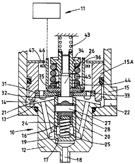
Figure 1 is a part sectional side elevation of the
first example of the valve, and
Figure 2 is a view similar to Figure 1 of the
second example of the valve.
Referring to Figure 1 of the drawings the valve


~~"'U 93/00540 PC1"/GB92/01033
21 1 1986 2
comprises a valve section 10 and an actuator 11. The
valve section 10 comprises a body 12 which is provided
with a peripheral flange 13 which locates against the
base wall of a recess 14 formed in a housing 15. The
flange 13 of the body 12 is held against the base wall of
the housing by an annular retaining member 15A which is
screwed into the recess 14.
The valve body 12 defines an open ended blind bore
16 which adjacent its blind end defines a seating 17
which surrounds an outlet 18. Moreover, adjacent the
seating there is defined an annular gallery 19 which by
way of passages 20 and slots 2l formed in the body
communicates with an inlet passage 22 formed in the
housing 15.
Slidable in the bore 16 is a cup shaped valve
member 24 the closed end of which is shaped for
engagement with the seating 17.
The valve member is biased into engagement with
the seating as will be explained, by a coiled compression
spring 25 which engages the base wall of the valve member
at one end and at its other end ;is located within a
recess formed in the end portion of a valve actuating rod
26. The actuating rod is of stepped form with its end
portion lying within the valve member being constructed
as a sliding fit in the internal surface of the valve
member and at its end remote from the valve member being
provided with a screw thread. The valve actuating rod 26
carries a transversely extending pin 27 the end portions
of which project into elongated slots 28 respectively
which are formed in the wall of the valve member 24.
The retaining member 15A is provided with an
internal step between which and the valve body is located
a stop plate 31 which also acts to transmit the clamping


~"~ 93/Oa540 PCT/GB92/01033
21 1-1986 3
force generated when the retaining member 15A is
tightened within the recess 14.
The valve actuating rod 26 has a number of
components mounted thereon the first of which adjacent
the enlarged end portion of the rod which lies within the
valve member, is a small washer 32 which extends with
clearance through the central opening of the stop plate.
Adjacent the washer is a reaction plate 33 and engaging
the reaction plate is the end of a tubular extension of a
spring abutment 34 which is engaged With the threaded
portion of the actuating rod.
Engaging the outer peripheral portion of the
reaction plate is an inturned flange 35 which is formed
at the end of a tubular member 36 which is coupled to an
armature forming part of the actuator 11. The actuator
includes a stator which carries Windings which are
energised When as will be explained, it is required to
lift the valve member from the seating.
A coiled compression spring 43 has one end
engaging a tubular portion of the spring abutment 34 and
its other end engaging a f fixed abuttaent surface .
Moreover, interposed between the spring abutment 34 and a
pressure plate 44 Which engages the inwardly extending
flange 35 is a further coiled compression spring 45 which
urges the flange into engagement with the reaction plate
33.
The extent of movement of the tubular member 36
and the armature when the windings of the actuator are
energised, is limited by an annular stop member 47 which
is engaged by an outwardly extending flange 46 on the
tubular member 36. The stop member is held in position
against the retaining member 15A by means (not shown) for
example, the body of the actuator 11.


1193/00540 PCT/GB92/01033
21 1 1986 4
The various components of the valve are shown in
the positions which they adopt when the windings are de-
energised. It will be seen that the reaction plate 33 is
in engagement with the stop plate 31 and that the valve
member is in engagement with the seating: A small
clearance exists between the pin 27 and the end walls of
the slots 28 so that the valve member is held in
engagement with the seating due to the force exerted by
the spring 25 and also by the fluid pressure acting on at
least the annular end of the skirt of the valve member.
When the winding is energised the force generated
is transmitted to the valve actuating rod 26 through the
spring 45 and the actuating rod will be lifted together
with all the components which are secured thereto,
against the action of the spring 43. The upward movement
will eventually take up the small clearance which exists
between the pin 27 and the end walls of the slots 28 and
when this clearance has been taken up the valve member is
moved upwardly away from the seating thereby allowing
flow of fluid through the valve outlet 18. The movement
of the valve member is halted by its engagement with the
stop plate 31. This engagement will halt the movement of
the actuating rod together with all the components
connected thereto. However, continued movement of the
annular member 36 and the arnnature can take place against
the action of the spring 45, the eventual movement being
halted by the engagement of the flange 46 with the stop
member 47. The engagement of the flange with the stop
member 47 leaves a small air gap between the faces of the
armature and the stator of the actuator. Moreover, a gap
will be established between the flange 35 and the
reaction plate 33.
When the windings are de-energised, the spring 45
tends to move the annular member and the armature in the
direction towards the seating and this movement assists

°


'~"~'<J 93/00540 _ PCT/GB92/01033
21119865
the movement of the actuating rod under the action of the
spring 43 towards the seating.- During.the movement of
the actuating rod 26 the valve member 24 will engage the
seating and continued movement of the actuating rod under
the action of the spring 43 will take place at the same
time compressing the spring 25, until the reaction plate
33 engages the stop plate 31. The inertia of the
actuating rod 26 together with the components connected
to it and also the annular member and the armature is
absorbed by the engagement of the reaction plate 33 with
the stop plate 31 and not by the engagement of the valve
member with the seating. The life of the valve member
and the seating is therefore extended as compared with
constructions in Which the engagement of the valve member
with the seating halts the movement of the various
components of the valve. Moreover, the small mass of the
valve member substantially eliminates valve bounce which
could otherwise take place without proper damping.
Turning now to Figure 2 of the drawings the valve
shown therein comprises a valve body 50 in which is
formed a through bore 51. The bore defines a seating
edge 52 adjacent which the bore is slightly enlarged, the
enlargement being connected by a-=passage 53 to a fluid
inlet 54. A port 55 opens into the bore at a position on
the opposite side of the seating edge and the port
communicates with a fluid outlet 56.
Slidable in the bore is a tubular valve member 57.
The valve member is shaped to co-operate with the seating
edge 52 and forms with the bore an annular chamber which
is in communication with the port 55. The valve is shown
in the open position in the drawing and upward movement
of the valve member so that it engages the seating edge
will prevent flow of fluid through the valve.
Extending within the bore in the valve member is


PCT/GB92/01033
21 1 1986
s
an actuating rod 58 which at one end is secured within an
armature 59 of an actuator 60. The arzaature is of
cylindrical form and is slidable within a core rube
surrounded by a Winding 61. The actuator also ir.:.ludes a
pole piece 62 located in one end of the core tube and a
yoke 63 extending about the winding. When the winding is
energised the armature and pole piece will assume
opposite magnetic polarity thereby creating a force
tending to move the armature upwardly. The extent of
movement of the armature is limited by the engagement of
a flange 64 on the armature with a stop face 65 defined
on a mounting member 66 secured to the valve body.
The actuating rod 58 extends through the valve
member and at its end is provided with a screw thread and
engaged with the thread is a first spring abutment 67
between which and the valve member is a first coiled
compression spring 68. Also mounted on the actuating rod
is a flanged lock member 69. Located against the
undersurface of the flange of the lock member is a shim
70 which is engaged by one end of a second coiled
compression spring 71. The other end of the spring 71 is
engaged with a second spring abutment 72 Which is
engagable with the end wall of the valve body 50. The
spring abutment 72 has an inwardly directed flange 73
engaged on one side by the spring 71 and engagable on its
other side by a flange at the adjacent end of the valve
member. The abutment 72 has an outwardly directed flange
74 engaged by one end of a third coiled compression.
spring 75 the other end of which engages a shim
positioned against a reaction surface formed on an
annular member 76 adjustably mounted relative to the
valve body 50. The open end of the annular member is
closed by a plug.
In Figure 2 the valve is shown in the open
position with the winding 61 de-energised. When the


WO 93/00540 " ~ - PCT/GB92/01033
21 1 1g86 7
winding is energised the armature 59 moves in the
direction towards the pole piece 62 and the movement of
the armature together with the actuating rod takes place
against the action of the spring 71. The valve member 57
moves with the actuating rod 58 until it engages the
seating 52 and continued movement of the actuating rod
and armature takes place against the action of the spring
71 and also the spring 68 until the flange 64 engages the
stop face 65. The impact loading of the valve member
with the seating is therefore kept to minimum. When the
winding 61 is de-energised the two springs 71 and 68
cause movement of the armature away from the pole piece
62 until the gap between the end of the armature and the
valve member is taken up whereupon the valve member is
lifted from the seating. The movement of the valve
member away from the seating is rapid due to the velocity
gained by the anaature prior to lifting the valve member
from the seating. The valve member 57 and the armature
59 move together under the action of the spring 71 until
the flange on the valve member engages with the flange 73
of the spring abutment 72. The inertia of the armature
and valve member is then absorbed by compression of the
spring 75 during which time the valve member moves beyond
the fully open position in whicl~'it is shown in the
drawing. Finally the valve member and armature are
returned to the position shown by the action of the
spring 75.

Representative Drawing
A single figure which represents the drawing illustrating the invention.
Administrative Status

For a clearer understanding of the status of the application/patent presented on this page, the site Disclaimer , as well as the definitions for Patent , Administrative Status , Maintenance Fee  and Payment History  should be consulted.

Administrative Status

Title Date
Forecasted Issue Date 2001-05-29
(86) PCT Filing Date 1992-06-10
(87) PCT Publication Date 1993-01-07
(85) National Entry 1993-12-20
Examination Requested 1999-04-29
(45) Issued 2001-05-29
Expired 2012-06-10

Abandonment History

There is no abandonment history.

Payment History

Fee Type Anniversary Year Due Date Amount Paid Paid Date
Application Fee $0.00 1993-12-20
Maintenance Fee - Application - New Act 2 1994-06-10 $100.00 1994-05-25
Registration of a document - section 124 $0.00 1994-06-28
Maintenance Fee - Application - New Act 3 1995-06-12 $100.00 1995-05-23
Maintenance Fee - Application - New Act 4 1996-06-10 $100.00 1996-05-21
Maintenance Fee - Application - New Act 5 1997-06-10 $150.00 1997-06-02
Maintenance Fee - Application - New Act 6 1998-06-10 $150.00 1998-05-20
Request for Examination $400.00 1999-04-29
Maintenance Fee - Application - New Act 7 1999-06-10 $150.00 1999-05-26
Maintenance Fee - Application - New Act 8 2000-06-12 $150.00 2000-06-05
Final Fee $300.00 2001-02-26
Maintenance Fee - Patent - New Act 9 2001-06-11 $150.00 2001-05-25
Maintenance Fee - Patent - New Act 10 2002-06-10 $200.00 2002-05-16
Maintenance Fee - Patent - New Act 11 2003-06-10 $200.00 2003-05-20
Maintenance Fee - Patent - New Act 12 2004-06-10 $250.00 2004-03-29
Maintenance Fee - Patent - New Act 13 2005-06-10 $250.00 2005-06-07
Back Payment of Fees $450.00 2005-06-17
Maintenance Fee - Patent - New Act 14 2006-06-12 $250.00 2006-05-05
Maintenance Fee - Patent - New Act 15 2007-06-11 $450.00 2007-05-07
Maintenance Fee - Patent - New Act 16 2008-06-10 $450.00 2008-05-12
Maintenance Fee - Patent - New Act 17 2009-06-10 $450.00 2009-05-14
Maintenance Fee - Patent - New Act 18 2010-06-10 $450.00 2010-05-11
Maintenance Fee - Patent - New Act 19 2011-06-10 $450.00 2011-05-11
Owners on Record

Note: Records showing the ownership history in alphabetical order.

Current Owners on Record
LUCAS INDUSTRIES PUBLIC LIMITED COMPANY
Past Owners on Record
CROSS, ROBERT KEITH
PANESAR, LUKHBIR SINGH
PHILLIPS, RONALD
Past Owners that do not appear in the "Owners on Record" listing will appear in other documentation within the application.
Documents

To view selected files, please enter reCAPTCHA code :


To view images, click a link in the Document Description column. To download the documents, select one or more checkboxes in the first column and then click the "Download Selected in PDF format (Zip Archive)" or the "Download Selected as Single PDF" button.

List of published and non-published patent-specific documents on the CPD .

If you have any difficulty accessing content, you can call the Client Service Centre at 1-866-997-1936 or send them an e-mail at CIPO Client Service Centre.


Document
Description 
Date
(yyyy-mm-dd) 
Number of pages   Size of Image (KB) 
Claims 1995-05-13 3 199
Representative Drawing 1999-10-14 1 37
Cover Page 2001-05-04 1 40
Representative Drawing 2001-05-04 1 18
Cover Page 1995-05-13 1 64
Abstract 1995-05-13 1 17
Description 1995-05-13 7 329
Drawings 1995-05-13 2 75
Claims 1999-06-22 3 108
Assignment 1993-12-20 7 307
Fees 2000-06-05 1 47
Correspondence 2001-02-26 1 53
Prosecution-Amendment 1999-04-29 1 34
Prosecution-Amendment 1999-10-20 4 148
Correspondence 2000-05-11 2 75
PCT 1993-12-20 30 1,049
Fees 2004-03-29 1 33
Fees 2005-06-07 1 28
Correspondence 2005-07-25 1 16
Fees 1996-05-21 1 60
Fees 1995-05-23 1 61
Fees 1994-05-25 1 67