Language selection

Search

Patent 2112346 Summary

Third-party information liability

Some of the information on this Web page has been provided by external sources. The Government of Canada is not responsible for the accuracy, reliability or currency of the information supplied by external sources. Users wishing to rely upon this information should consult directly with the source of the information. Content provided by external sources is not subject to official languages, privacy and accessibility requirements.

Claims and Abstract availability

Any discrepancies in the text and image of the Claims and Abstract are due to differing posting times. Text of the Claims and Abstract are posted:

  • At the time the application is open to public inspection;
  • At the time of issue of the patent (grant).
(12) Patent: (11) CA 2112346
(54) English Title: AIRSPRING PISTON AND AIRSPRING ASSEMBLY
(54) French Title: PISTON DE SUSPENSION PNEUMATIQUE ET SUSPENSION PNEUMATIQUE CONNEXE
Status: Deemed expired
Bibliographic Data
(51) International Patent Classification (IPC):
  • F16F 9/04 (2006.01)
  • B60G 17/052 (2006.01)
(72) Inventors :
  • ARNOLD, JOHN ERIC (United States of America)
(73) Owners :
  • THE GOODYEAR TIRE & RUBBER COMPANY (United States of America)
(71) Applicants :
  • THE GOODYEAR TIRE & RUBBER COMPANY (United States of America)
(74) Agent: SIM & MCBURNEY
(74) Associate agent:
(45) Issued: 2003-07-15
(22) Filed Date: 1993-12-23
(41) Open to Public Inspection: 1995-03-30
Examination requested: 1999-11-03
Availability of licence: N/A
(25) Language of filing: English

Patent Cooperation Treaty (PCT): No

(30) Application Priority Data:
Application No. Country/Territory Date
08/129,933 United States of America 1993-09-29

Abstracts

English Abstract


An airspring piston which combines the features
of being easily assembled, providing full air volume
utilization which contributes to a low spring rate of
an airspring assembly, a rounded outer peripheral edge
to facilitate its assembly with a beaded flexible
airsleeve and a bead retention lip to retain a beaded
airsleeve on the piston in low or no pressure
situations. An airspring assembly comprised of the
aforementioned piston, a beaded flexible airsleeve and
an upper retainer.


Claims

Note: Claims are shown in the official language in which they were submitted.


-5-
WHAT IS CLAIMED IS:
1. An airspring piston comprising:
(a) a top plate having an outer peripheral
edge which is rounded perpendicular to the
general plane of the plate and a plurality of
vents;
(b) a bottom plate axially spaced from the
top plate;
(c) an inner tubular support connected
between the top and bottom plates; and
(d) an intermediate outer wall connected
between the top and bottom plates, the upper
portion of which includes a rounded shoulder
inwardly and downwardly sloping to a horizonal
flange and a beat seat area generally
perpendicular to the flange and connected to the
peripheral edge of the top plate such that the
outer surface of the bead seat is radially
inwardly offset from the outer peripheral edge of
the top plate to form a bead retention lip.
2. The piston according to claim 1 wherein the
bead seat area is tapered from about 2° to about 6°
inwardly from the flange.
3. The piston according to claim 1 wherein the
lip has a radial dimension from about 1 mm to about
2.5 mm.
4. The piston according to claim 1 wherein the
lip has a radial dimension from 1.2 mm to 2.0 mm.
5. The piston according to claim 1 wherein the
lip has a radial dimension from 1.3 mm to 1.8 mm.


-6-

6. An airspring assembly comprising an
airspring, an upper retainer and a beaded flexible
airsleeve wherein the airspring piston is as described
in claim 1.

Description

Note: Descriptions are shown in the official language in which they were submitted.


-1-
AIRSPRING PISTON AND .AIRSPRING ASSEMBLY
Field of the Invention
This invention relates to an airspring piston.
More particularly, it relates to an airspring piston
used in an airspring assembly.
Bacl~around of the Invention
Stamped steel airspring pistons have been in use
for many years, but those which have provided for
maximum air volume to attain the desirable low spring
rate have not provided for flexible airsleeve bead
retention. Aluminum and plastic pistons with
retention barbs are usually costly to produce because
they usually require machining and, furthermore, the
large amount of material required to reinforce those
types of piston reduces the amount of air volume
available for operation of an airspring assembly.
Summary of the Invention
One of the features of the present invention is
that the airspring piston can be easily assembled. It
is comprised of three metal stampings and one metal
tube. The design of the top plate stamping allows it
to function as a bumper reaction plate in an airspring
assembly during severe jounce movements while in
operation. It also serves as a flexible airsleeve
bead guide to provide for easy installation of the
airsleeve onto the piston. Moreover, its relative
sizing in comparison to the bead seat area allows it
to serve as a bead retention lip: The cylindrical
piston provides support for a rolling lobe flexible
airsleeve during operation. It can be contoured to
modify the spring rate, however, tYze illustrations
show it as being cylindrical.

CA 02112346 1999-11-17
- 2 -
There is also disclosed an airspring assembly comprised
of the piston, a flexible beaded airsleeve, and an upper
retainer.
According to another aspect of the present invention,
there is provided an airspring piston comprising:
(a) a top plate having an outer peripheral edge which is
rounded perpendicular to the general plane of the plate and a
plurality of vents;
(b) a bottom plate axially spaced from the top plate;
(c) an inner tubular support connected between the top
and bottom plates; and
(d) an intermediate outer wall connected between the top
and bottom plates, the upper portion of which includes a
rounded shoulder inwardly and downwardly sloping to a
horizonal flange and a beat seat area generally perpendicular
to the flange and connected to the peripheral edge of the top
plate such that the outer surface of the bead seat is radially
inwardly offset from the outer peripheral edge of the top
plate to form a bead retention lip.
Description of the Drawings
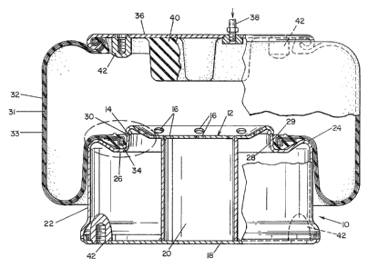
Fig. 1 is a cross-sectional view of an airspring assembly
utilizing the airspring piston of the instant invention.
Fig. 2 is an enlarged view of the encircled portion of
Fig. 1.
Fig. 3 is a bottom plan view taken along line 3-3 of Fig.
2.
Fig. 4 is a top plan view of the piston of the instant
invention.
Detailed Description of the Invention
The airspring piston of the instant invention shown

CA 02112346 1999-11-17
- 2a -
generally at 10 is comprised of a top plate 12 having an outer
peripheral edge 14 which is rounded perpendicular to the
general plane of the plate 12 and has a plurality of vents 16.
Axially spaced from the top plate 12 is a bottom plate 18
connected together by an inner tubular support 20 and
intermediate outer wall 22. The intermediate outer wall 22 has
an upper portion which includes a rounded shoulder 24 which
slopes inwardly and downwardly to a horizonal flange 26. The
upper portion of the intermediate outer wall 22 also includes
a bead seat area 28 which is generally perpendicular to the
flange. While it is stated that the bead seat area 28 is
generally perpendicular to the flange 26, it should be
appreciated that it is preferred that the bead seat area 28 be
tapered from about 2° to about 6° inwardly from the flange 26.
The bead seat area 28 is connected to the peripheral edge
14 of the top plate 12 such that the


).
i- ~ J y
- ~ _ ~. ! ~ ~ ~~ J
outer surface 29 of the bead seat 28 is radially
inwardly offset from the outer peripheral edge 14 of
the top plate 12 to form a bead retention lip 30.
The radial dimension 35 of the lip 30 can be from
about 1 mm to about 2.5 mm, preferably from 1.2 mm to
2.0 mm and most preferably from 1.3 mm to 1.8 mm.
The airspring piston is particularly suitable to
be used in an airspring assembly comprised of the
piston 10, a generally cylindrical flexible airsleeve
32 having reinforcement layers 31 and 33 and having at
at least one end thereof a relatively inextensible
airsleeve bead 34 connected to the bead seat area 28
of piston 10 and an upper retainer 36 connected to the
other end of airsleeve 32 by any suitable means. The
upper retainer 36 includes a rubber bumper 40 which
serves to protect the airspring assembly during severe
jouncing. The upper retainer 36 also has an air inlet
38 for adjusting the pressure within the airspring
assembly. Both the upper retainer 36 and the bottom
plate 18 of piston 10 can have a plurality of means
for fastening 42 the airspring assembly between an
unsprung and a sprung portion of a vehicle.
The vents 16 in the top plate 12 of the piston 10
allows the entire volume of piston 10 to be used in
conjunction with the airsleeve to provide a desirable,
low spring rate. The suing and the rounding of the
outer peripheral edge 14 of top plate 12 provides for
easy assembly of the flexible airsleeve unto piston
10. The bead retention lip 30 prevents the airsleeve
32 from coming off piston 10 during periods of low or
no air pressure.
While certain representative embodiments and
details have been shown for the purpose of
illustrating the invention, it will be apparent to
those skilled in this art that various changes and

-- _4_
modifications may be made therein without departing
from the spirit or scope of the invention.

Representative Drawing
A single figure which represents the drawing illustrating the invention.
Administrative Status

For a clearer understanding of the status of the application/patent presented on this page, the site Disclaimer , as well as the definitions for Patent , Administrative Status , Maintenance Fee  and Payment History  should be consulted.

Administrative Status

Title Date
Forecasted Issue Date 2003-07-15
(22) Filed 1993-12-23
(41) Open to Public Inspection 1995-03-30
Examination Requested 1999-11-03
(45) Issued 2003-07-15
Deemed Expired 2004-12-23

Abandonment History

There is no abandonment history.

Payment History

Fee Type Anniversary Year Due Date Amount Paid Paid Date
Application Fee $0.00 1993-12-23
Registration of a document - section 124 $0.00 1994-06-30
Maintenance Fee - Application - New Act 2 1995-12-25 $100.00 1995-09-27
Maintenance Fee - Application - New Act 3 1996-12-23 $100.00 1996-09-26
Maintenance Fee - Application - New Act 4 1997-12-23 $100.00 1997-10-01
Maintenance Fee - Application - New Act 5 1998-12-23 $150.00 1998-10-08
Maintenance Fee - Application - New Act 6 1999-12-23 $150.00 1999-10-13
Request for Examination $400.00 1999-11-03
Maintenance Fee - Application - New Act 7 2000-12-25 $150.00 2000-10-16
Maintenance Fee - Application - New Act 8 2001-12-24 $150.00 2001-11-14
Maintenance Fee - Application - New Act 9 2002-12-23 $150.00 2002-11-12
Final Fee $300.00 2003-04-04
Owners on Record

Note: Records showing the ownership history in alphabetical order.

Current Owners on Record
THE GOODYEAR TIRE & RUBBER COMPANY
Past Owners on Record
ARNOLD, JOHN ERIC
Past Owners that do not appear in the "Owners on Record" listing will appear in other documentation within the application.
Documents

To view selected files, please enter reCAPTCHA code :


To view images, click a link in the Document Description column. To download the documents, select one or more checkboxes in the first column and then click the "Download Selected in PDF format (Zip Archive)" or the "Download Selected as Single PDF" button.

List of published and non-published patent-specific documents on the CPD .

If you have any difficulty accessing content, you can call the Client Service Centre at 1-866-997-1936 or send them an e-mail at CIPO Client Service Centre.


Document
Description 
Date
(yyyy-mm-dd) 
Number of pages   Size of Image (KB) 
Cover Page 2003-06-11 1 53
Cover Page 1995-06-03 1 29
Claims 1995-06-03 2 39
Drawings 1995-06-03 3 122
Abstract 1995-06-03 1 17
Description 1999-11-17 5 157
Representative Drawing 2002-10-01 1 27
Representative Drawing 1999-07-12 1 45
Correspondence 2003-04-04 1 50
Prosecution-Amendment 1999-11-03 1 54
Assignment 1993-12-23 7 282
Prosecution-Amendment 1999-11-17 7 212
Fees 1995-09-27 1 59
Fees 1996-09-26 1 94