Note: Descriptions are shown in the official language in which they were submitted.
2112 ~ 4 9
~CHO ~ANC~E~ WIT~ ADAPTIVE SuP-
PR~S5ION OF RES~DUAL ECHO LEVEL
~ackground of the Invention:
This invention relates to an echo canceller
ope~ble a~ an e~ho c~ncHlling device.
In a long-di~tance ~elephone n~two~X, a local
telephone ~ub~tAtion i~ connected ~hrough a hybrid
trAn~ormer ~n~ A two-wire line to a plurality o~ remote
tclephone ~ t~ion~. An echo c~nc~ller i~ connected to
the hybri~ tran~ormer between two ~ire3 o~ the two-wire
line. A sent ~igndl originate~ at the loc~l telephone
su~station and is deli~ered throu~h the hybrid
tran~former to th~ echo canceller ~nd thence to th~
ro~ote telephone ~ub~tationsA For reception at the lo~al
telophone ~ub~tation, a received ~ignal originates at one
o the remoto telephone sub~t~tion~ And i~ d0livere~ to
the echo canceller ~nd thenco ~o the hybrid trans~orm~.
lt i~ u~ual ln the ort to reer to the 4çnt
~ign~l A4 a send-in signal and a send-out si~nal while
tran6mi~ted ~rom the hybrid tr~n~former ~o the echo
canceller ~nd from the ~cho canceller tow~rd~ the remote
telephone ~ub~tations. The received signal is cAlled ~
receiv~-in signal whil~ tran~mitted ~rom one of the two
wiree to an echo canceller.
6~ 8~1 1681 OS8 0N/10: 61 ~S/I 1: 61 86 ,L~ Z 1 (NO~ a3~ l~O~O~ ~o~
iJ1125~9
As will later ~ described, a conventional echo
c~ncelling de~ice is not exsmpted ~rom f2ctors which
deteriorate ~ quality of ~peech tran~mi~ion eithex in a
bidirectional communication state or when a channel no~e
5 or a background noise ia high.
Summary of, the Invention:
.
~ t is there~ore an object of this invention to
provide an echo cancelling device ~hich can precisely
~udg~ a re~idual echo control op~rAtion by estimating a
10 se~dual echo level and c~n suppress with ~o irrelevant
feeling a residual echo, channel noi6e, and/or b~ckground
noi~e to achie~e ~ high quality of speech transmission
even elther in ~ bidirectional communication ~tate or
when the channel noi~e or the bacXground noise is high.
o~her o~jectfi of this in~ention will beaome clear
a~ the description proceeds.
On ~etting rorth th~ g~ Bt 0~ this in~ntion, it
i~ pos~ible to understand that an echo cancelling de~ice
co~pri~e~ an echo c~nceller responsive to a ~d-in
20 ~lgnal and a rec~ive-in ~ignal ~or producing a residual
signal in which ~n echo signAl is c~nc~llod.
According to thi6 invention, the above-under~tood
~cho cancelling de~ice further comprises a residuAl e~ho
level ~t~mator se~ponsive to the r~sidual sig~al for
25 ostimating a residu~l e~ho lev~l ln the re~idual signal
ane for pro~cing ~ threshold signal with a threshola
lo~el oqual to the re~idual e~ho level; Qnd a re~idual
echo ~uppre~o~ responslve to the r~cei~e-i~ signal, the
~/S d 8~ 11 68 1 0S8 ON/1 0 : 6 1 .1 S/11: 6 1 86 ,L~ Z l (NO~) ~a~ o~o~ ~OH~ -
rJ~ ~ ~L 2 ~
res$dual signal, and the threshold si~nal for produci~g a
send-out signal with a re~idual echo adaptively
~uppressed in response to the threshold level.
Brief De~cription of the Drawing:
S Fig. 1 i~ a block diagram of a conventional echo
c~ncelllng device;
F$g. 2 is a block diagram of A center cllpper
circuit (an N~P circuit) u~od in th~ eeho c~ncelling
device illus~rate~ ln Eig. l;
Fig. 3 ls a block diagxam o an echo caneelling
de~ice ~ccording to an embodiment of this invention~
Fig. 4 i~ a block ~iagram o~ a residual echo
level efitim~tor of the echo cancelling dovice illustrated
in Fig. 3; ~nd
Fig. ~ is a block diagram of a residu~l echo
~uppre~oor of tho echo canc~lling de~ice illustrated in
Fig. 3.
De~cription of the Preferrad ~bodiment;
Re~errlng So Fig. 1, a conv~ntional echo
20 cane-lling dovice will ~irst bo d~acribed for a bettsr
underst~n~ing o~ thi~ invontion. Thc echo canc~lling
do~ico of ~ig. 1 iB u~e~ in ~uppre~slon o~ an echo ~lgnal
E~HO ~hich result~ ~rom an 1mpedanca ~ismatch at 2 hybrid
transfor~er 12.
~he echo o~ncelling devlco compri~e~ an echo
canc~llor 13. ~esponoi~e to a sen~-in ~ignal SIN and ~
ro~eive-in siqnal RIN, the ~cho canceller 13 produces a
re~iduAl signal RE8 in which the echo ~ignal ~C~O is
~/9 d ~116810~'0N/10:61 '~S/11:61 ~6.l~ Olq) ~a~al~o~o~ i~O'd~
~13 2~4~
cancelled. The echo canceller 13 comprises an echo
e~timating circuit ~namely, ~n echo path estimating
circuit) 131 and a subtracter 132. Responsive to the
receive-in signal RIN and the re~id~al Rignal RE5, the
5 echo estimating circuit 131 estimate~ an echo estimation
~ignal. The subtracter 132 subtracts th~ echo estim~tion
signal from the ~end-i~ signal SIN and produces the
re~i~ual ~ignal R~S.
The ~cho c~ncelling deviee ~urther comprises a
10 bidirectional cem~unication ~tate detector 14.
~e~ponsive to the send-in signal SIN ~nd th~ receive-in
olgnal RIN, the bidirectional communiCAtion state
detector 14 produces an inhibit signal I~H when the
receive-in slgnal RIN has a lev~l which i~ gr~tor ~han
15 tha~ of the sena-in signal SI~. ~hus, the bidirec~ional
communication ~t~to detector 14 produces the inhibit
signal INH when a unidirection~l communic2tion Rtate i~
brought ~bout by a receiving speaker or talk~r ~not
~ho~n) which i~ a counterpart o~ ~ transmitting speaker
20 or t~lknr 11 and which produce~ the rec~iVQ-in signal
RIN. The inhibit ~i~n~l INH prevcnt~ t~e ocho ~stimatlng
clrcuit 131 ~rom producing th~ Qcho estimation sig~al.
Thus, the echo c~nceller 13 e~timateo an echo
p~th under a certain rentriction. Thi~ results ln remaln
25 o~ A rc~idual echo e~en when an echo i~ cancelled with
the echo path be~t e~timated. In order to forcibly
s~ppres~ ~uch a ~esidual echo, an ~P (nonllne~r
proces~or) circ~it ~na~ely, a center clipper circui~) 15
6Z'L I 8~1 1681 OS8 0,1/10: 61 ~S/I 1: 61 86 .L~ Z 1 ~NOYl) ~a3~ l~o~o~ ~o~i
.-. . . ~ . ., .
.. - . .................. . .
i.. .... . ..
2 ~ 4 9
is u~ed ~ a residual echo control circuit in the manner
depictsd in ~ig8 . 1 and 2. Accordlng to p~ior art, the
NL~ circuit 15 comprises a first level detector 21 for
detscting a levsl of the residual signal ~S and a second
5 levsl detector 22 or detecti~g a levsl of the receive-in
6ignal R~N. ~he NLP circuit 15 i5 put in opsration by a
level comparison and NLP opera~ion ~u~pension judge
ci~euit 23 when a dii'erence bstw~en an output of ~he
~ir~t le~el deteator 21 and another output of ~hs secon~
10 le~el det~to~ 22 is ~udged to be higher than a certain
~alu~ and furthermore when ~he ls~el of the residual
signal RES is ~u~ge~ to be low~r than a certain value to
fiwltch the ~end-out sign~l SOUT from the ~e~idual signal
R~S to a generat~d signal of a low lsv~l ~or examp~e,
15 white noiss or quiescsnt) by a h~itch 25 and thereby to
prevent th~ resl~u~1 scho from leaking into the s~nd-out ~ ;
si~n~l 50UT whil~ the ~nldirectional communic~tion ~t~te
i~ brought about by the receiving speaker. Ths g~neratod
Bignal is ~oneratsd by ~ ~ignal generator 24.
According to ~udgement of NLP ~center clipper)
operation by s~ch level comparison, optimal ~udgement ia
not ~lways in~ured ~tner in a bidir~ctional
communication state or when a channel noi~e levsl or
background noi~e level is high. As he~e~n called, the
25 optim~l juagemen~ means inst~ntaneou~ suspen~ion o~ the
N~P operation upon occurrence of an interrupting signal
p~o~ced by the tran~mitting sp~aker 11 and inStAntAneOUs
aeti~atio~ of the N~P operation in the absence of euch an
6~!8 d ~116810~8 ON/10:61 ~S/11:61 86,L~ ZI (Non~ ~a~al~o~o~ Y~O'd~
.
6 .~ 9
interrupting signal. An error in the j~d~ement re~ults
eithe~ in suppre5~ion of a speech signal of the
transmitting ~peaker 11 or in return of the residual
echo. When a method is adopted t~ switch lnto a certain
5 ~ignal upon initiation o~ the NLP operation, either a
di~continuous feeling or an irreleYant 4eeling is
unavoidabl~ due to a ~ignal le~el diffe~ence and~or a
tone difference be~ore an~ after switching. In this
manner, the con~entional echo cancelling device is not
10 exempted 4rom factors which deteriorate the quali~y of
~peech tran~mi6sion ~ither in the bidirec~ional
communication state or when the channel noise or the
backgroun~ noi~e i~ high.
Thi~ invention has b~en inven~ed in su~h
15 background~ an~ provides an echo cancelling de~ice whic~
can preci3ely judge a residual echo control operation ~y
ootimating a resldual echo level and can suppre~s with no
irrelevAnt ~eeling the resldual echo, the ohannel noise,
and/o~ the backgroun~ noise to achleve a high quality of
20 6p~ech tran~mis~ion even either in the bidirectional
communioatlon state or when the ~hann~l noi~e or the
backgroun~ noi~e is high.
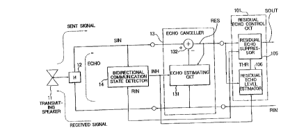
~ ur~ing to Fi~. 3, an Hcho cancelling device
accoraing to a preferre~ e~bodlment of ~hi~ invsntion
25 compri~os similar p~rt~ ~esignate~ by llke reference
numeral~. The ~cho cancelling device compri~e~ a
re~l~ual echo con~rol circuit 101 compri~ing ~ residual
echo suppr~or 105 and a r~idual echo le~el estimator
6~,'6 d 8~1 16810~8 ON/10: 61 ~S/~ I: 61 86 ,L~ Z 1 (NO~) Ya3s I~OLO~ ilOld~
, ; .
. : ,; ~ . ;`
. : - . : .: , . ` .
J1125~
106. Respon~ive to the residual signal RES, the resiAual
echo level estimator 106 estimate~ a residual ec~o level
in the residual signal RES and produces a thre~hold
signal T~R with a threshold level equal to the residual
5 echo level. The re~idual echo level estimator 106 Xeeps,
in respon~e ~o the inhibit signal IN~, the threshold
level at thH re~ldual echo lev~l estimated immediately
be~ore the inhibit signal INH i9 produced. Respon~ive to
the recci~e-in s1gnal RIN, the residual signal R~S, and
10 the thr~shold signal THR, ~he re~idual echo suppreSsor
10S prod~cc~ the send-out ~ignal SOUT with a residual
echo adaptively suppr8~.sed in response to the thre~.hold
level.
The scho cancelling d~ice of Fig. 3 will ~e ~:
15 describe~ more in detail. Thc bidirectional communica- :
tion ~ate detecto~ 14 ls supplied ~ith the ~cnd-in
~ignal SIN through the hybrl~ tran~former ~H) 12 by the
t~n~mitting ~pe~ker 11 ~nd with the rcceive-in ~ignal
R~N to detect a bidir~ctlonal communication state an~ to
20 con~rol estimatin~ operation of the echo e~timating
circuit 131 whiah e~timatos ~y an ~daptivo FIR (~inite
impulee ~espon~e) filtor an echo signal re~ulting from
the r~ceive-in ~ign~l RIN into the aen~-~n ~ignal SIN.
The echo e~tlmatlng circuit 131 produce~. th~ echo
25 estimati~n signal. The ~u~tracter 132 of the echo
cs~celler 13 6ubtracts thc echo estimation sign~l ro~
th~ ~end-in signal SIN to produce the resldual signal RES
~nd control~ an echo path ~stima~ion operation and
6G~;OI d ~GI 16810S~ ON/10 61 ~S/GI :61 ~6 ,~G GI ~NO~ Ya~al~O~O~ ~O~
~ :1 12 ~ 4 9
~uspension of the estimation operation. In this event,
the echo estimating circuit 131 is responsive to the
receive-in signal RI~ and to the resi~ual signal ~ES and
estimates ~he echo estimation signal so that ~he residual
5 ~ignal RES be~omes equal to zero. Th~ residu~1 echo
control clrcuit 101 controls a resldual echo by the
resldual ~ignal RES a~d the recelve-in signal RIN to
produce a 8end-out signal SOUT.
It is noted hexe that the bidixectional
10 communication state detector 14 produces the inhibit
signal IN~ when the ~nidirectional communication state is
brought about by the receiving spea~er or talker ~not
sho~4n) whibh i~ a count~rpart of th~ transmitting speaker
or talker 11. That i8, the bidirectional communica~ion
state ~etector 14 produces th~ inhibit signal IN~ when
the level of the receive-in signal RIN is greater than
th~ level of the s~nd-in signal SIN. ~he inhibit signal
INH prev~nt~ the echo estimating circuit 131 ~rom
producing the echo est~m~tion signal. ~he residual echo
control circuit 1~1 co~prises the re idual echo le~l
ostimator 106 for e~timating the resi~l ocho lsvel
ba~ed on tha resldual ~ignal RES ~pplied f~o~ ~he ocho
~anceller 13 to producs the threshold signal THR ~nd the
rs~idual echo ~uppre~80r 105 for adaptively co~trolling a
8uppression amount for th~ re~dual echo bas~d on th~
threshol~ signal T~R supplied from the residual echo
le~el estimator 106.
6~/1I d 8~116810~8 ON/I0:61 LS/~1:61 86,l~ ~I(NOYI~ ~a3a I~OLO~ iiO~
~254!9
~ urning to Fig. 4, the recidual echo leve~
estimator compriseB a residual signal level detector 201
for detec~ing a lev~l o~ the residual ~ign~l ~ES a~ a
re3idual ~ignal level and a level memory 2~2 in which an
5 e~timated level of the residual echo i~ stored as a
~tored level. A cubtr~cter 203 serves a~ an estimator
di~ference calculator which ~alculates an estimator 1~
di~ference equal to the residual signal level minus the
~tore~ level. An ~stimator count~r 204 has an estimator
10 count va~ied by the e~timator level dif~eren~e into an
estim~tor v~ried count wit~ ~he estimator varied count
kept unv~ried when ~upplied with the inhibit signal INH.
A connection l~ne 204' aerve~ a~ a level v~ing unit
which varies by the estimator varled count the stor~d
15 lovel into the residual echo level.
The estimator counter Z09 i5 counted up and down
to h~vo the cHti~tor v~ried count when the estl~ator
level dife~ence is positiv~ ~nd negati~e. The
co~nection line 204' ~r~c~ th~ store~ level higher and
20 lower into tho residual echo levcl when the e~timator
counter 204 i~ counted up and ~own.
The ~timator counter 204 is counted up and d~wn
event~ally to h~ve zero and ~ull count~. The ~onn~ctlon
llne 204' varies the sto~ed level by 1 dB when the
25 esti~ator count~ 204 ha9 the zero and the ull counts.
Th~ re~ldual echo levcl estimatin~ circuit 106
will ~e described more in ~etail. The residual signal
level d0tector 201 d~tects a levcl o~ the re~idual ~ignal
6~,~1 d8~116810S80N/10:61 lS/~1:61 86,L~ZI(NOW) ~a~ olo~o~
2~a~9
RES. Stored in the level me~ory 202 is an es~imated
value of the re6idual echo level The s~btxa~ter 203
6u~tra~ts an output of the level memory 202 ~rom an
output of the residual level detector 201. When the
5 inhibit signal IN~ is not produced, ths es~imator counter
204 varie~ by its counter value the valuo stor~d in the
level memory 202 ~i~h the coun~er value varied by ~n
output of the subtracter 203. The abo~e-mentloned
threqhold signal THR is produced with the value stored in
10 the level memory 202.
Turnlng ~o Fig. 5, the residual echo suppres~or
105 compri~ a resi~al signal level d~tector 301 ~hich
~J s~ m~ lar in Btr~cture and in operation to the residual
signal level detector 201. A roceive-in sl~nal level
15 detecto~ 303 det~cts a le~el of ~he receivo-in qlgn~l RIN
as a receive-in signal l~vel. Connected to the resia~al
sign~l level dstector 303, a comparator 302 comp~e~ the
r~idu~l qignal le~v~l with the reeeive-in signal level of
the re6idual sign~l level ~etector 3~1 to prod~ce a
Z0 compAra~or output signal ~pre~entative o~ ~irst and
~econd results when the residual sign~ vel iq not
high~r than the receive-in ~ ~ gn~l level and when the
re3i~unl e~gnal l~vel i~ highcr than the receive-in
Big~l lev~l.
~ ~ele~tor 300 ~ re~ponsive to the thre~hold
si~nol THR nnd the ~ompar~tor outpu~ qignal and selecte
one o~ higher and lower le~els a~ a selected level when
the comparator output slgnal represents the ~irst ~nd the
BG/~I d 8~1 l68l0S8 ON/I0:61 ~S/8l :61 86 ,L~ Z 1 (NOW~ ~a3sl~0~0~ lYO~
~ ~ ;
11 ~112~i9
~econd results. The higher level is eq~al to the
thre~hold level plus a first level (n~mely, an A le~el).
Ths lo~er le~el is aqual ~o ths threshold level plu~ a
second l~v~l (namely, a ~ level) which is lower than the
5 first level ~he A level).
A ~uppres~io~ amount deciding unit 300' is
rexponaive to the residual signal level and to the
selected le~el ~nd de~ides a 6uppres~ion amount dependi~g
on a ~Uppre~JOr 18v~1 al~f erence equal to the selected
10 level minus the residual signal l~vel to produce a
~uppres~ion signal indicative o~ the suppression amount.
A 8Uppression circui~ 308 iB responsive to the residual
Jign~l R~S and th~ 3uppression ~ig~al and ~uppressee the
re~ldual eaho by thQ suppr~ssion amount to produce the
15 ~end-out ~ign~l SOUT.
The sel~ctor 300 comprise~ a first adder 304 ~or
calculating the hlgher l~vel by a sum of the threshold
l~vel ~nd the ~irst level ~A lovel~. A ~econd Addor 305
c~lculate~ the lower level by a 6um of the threshold
20 level ~n~ the ~econd le~el ~B level). Responsive to th~
hlgho~ ~nd th~ lowor le~els an~ controlled by the
co~parator output ~lgnal, a switch 309 p~o~uco~ tho
selectod level ~hen the comp~r~tor output s~gnal
~presents the fir~t snd the second roRults.
~he suppres~ion amount deciding unl~ 300'
compri~s~ a subtracter 306 ~hich serves a~ A ~uppresgor
tl~forence calculator which calculate~ th~ ~uppressor
level diff~rence by subtracting the residual sign~l level
6~/~1 d ~1 16810~ ON/I 0: 61 ~S/~ I: 61 ~6 ,L~ Z 1 (NOW~ ~a3x l~O~O~ ~lO'd~
,: "~ , ,: , ..
i~ 2 5 4 9
from the selec~ed level. A suppres~or counte~ 30? counts
up and down a ~uppressor count lnto a ~uppressor varied
cou~t when the suppre550r level difference i~ positi~e
and negative. RaSponsive to the s~ppressor varied aount,
5 a 6uppre~sion amount deciding circ~it ~10 produces the
3uppres_ion signal ~ith the suppression amount varied by
the ~uppre~or varied count.
~he ~Uppre~qar oounter 307 counts up and down the
~uppressor count to ha~e zero ~nd ~ull 6uppressor co~nts.
10 In thiR~ event, the suppresqion amount deciding ci~e~i~
310 produce~ the 6uppress~on Rignal with the suppre9~ion
~mount r~isod and reauced by 1 d~ each time when the
BUppre~or count counts up to th~ full ~uppressor count
and down to the zero count.
~he re~idual ~cho suppres~or 105 will be :~
descrlbed more in d~tail. ~he residual level detecto~
301 dete~ts the level of the residu~l signal ~S. The
receive-in slgnal lovol detector 303 detect~ A le~l o~
th~ recelve-in ~ignal RIN~ A oomparator 302 co~pares
20 output~ o~ the r~idu~ nal level detector 301 and o~
the rocoive-in ~i~nal levcl ~otoctor 303 ~ith eaah other.
The ~ir~t a~a~r 304 calculates the higher level by a 9Um
o~ the thr~shold level and the first level ~nam~ly, the
level A) ~ mentioned above. The second adder 305
25 ¢alculate~ the lower le~ol by a ~um of the th~e~bold
lev~l and the second le~l tnamely, the lev~l B). ~y an
output o~ the comp~rator circuit 302, the ~witah 309
3witches bet~een an output of the ~irqt a~der 304 and an
6~/SI 1 ~116810S~ ON/I0:6i lS/~1:61 86,L~ NOW) Ya~ o~o~ ~o~
~1 ~.2~9
13
output of the second adde~ 305. The subtracter 306
subtracts the ou~pu~ of the second level detector 301
4rom an output of the ~wltch 309. The supp~es~qor counter
307 varies its counter value in compliance with an output
5 of the subtrac~r 306. The suppre~sion amou~t d~cision
circuit 310 decide~ the suppression ~mount in accordance
with the output of the suppre~or counter 307. The
qu~pre~sion circuit 308 giveQ the s~ppre~ion amoun~ to
the resid~al ~gnal R~S to produee the send-out si~nal
lO SOUT .
It is noted here that the re~idual signal le~el
detector 201 oS ~ig. 4 ~ay be used as the residual si~nal
lovel detector 301.
~eferring to Flgs. 3 to 5, operation will now be .
15 dcscr~bnd o~ the embodiment ~tructured as above in
accord~nce with this invention. In Fi~. 3, the residual ~ :
echo level sstimator 106 ~tably cstimPteq the residual
ocho level from ths residual ~ignal RES produ~ed while
the ocho path estim~t1on operatlon is in pro~re~s in ~h~
2~ echo canccller l~.
More pa~tioularly, F1g. 4 ~ill bc referred ~o.
Tho re~idual 4ignal level det~tor 201 i~ ~upplied with
the residu~l slgnal RES ~nd mea~ure~ it~ level, ~hich
compa~d with the e~timated value sto~ed in th~ level
25 mamory 202. A ~e~ult of comp~ri~on coun~ up and down
the e~timator counte~ 204. ~he es~ima~e~ value iB
incremented and decr~ented b~, ~or example, l ds when
the aount ~ 6 equal to zero and whan ~he count is full
6G/9I d 8~11681OS8 ON/I0:61 ~$/8I:61 86 ,l~ ~1(NOYI) ~3~ 0.~0~ Y10
`.,'~ ..,.s.`.-'''' ''
.3~ll2rj~9
14
Ifor examplc, 200). In this manner, it becomes possible
to obtain a certain threshold level that ~atches a
current channel. ThiC level varies, when initial
convergence of the echo canceller 13 is attained, from a
5 great value to a i~mall value and h~ a relatively great
value ~nd a ~el~tively small value ~hen oither the
channel noi~e or the background noi~e i4 high and when
the echo is ~uffieiently cancelled to r~duce the noise
lovel, resp~ctively.
In Fig. 3, based on this threshold le~el, tbi~
reisidual echo suppressor lOS ~udgea whether or not the
~lgn~l R~S should be suppreJ3ed. The suppre~sion amount
~or ex~mple, attenu~tion or noise supply) is thereby
controlled and adapted to the comm~nic~tio~ state at that
15 iniatAnt of time. The aiscontinuous eeling and the
irrclevant feeling Are avoide~.
MorH 6pecifically, Fig. 5 ~ill be referred to. A
combinatlon of the residual level detector 301, the
receivo-~n i~ign~1 lev~l dctector 303, and the comparator
20 302 compa~es the lc~ol of th~ re~idual ~ gnal RES with
the lev~l of the receive-in ~ign~l ~IN. If the lev~l o~
the recolve-in ~ign~l RIN is far highox (for ex~mpl~, 24
~B~ in thi~ cas~, in the unidixectional communicotion
~tate o~ the receiving ~peaker), the first adder 304
2S c~lcul~te~ a sum o~ th~ abo~e-mentioned thr~shold level
and a relatlv~ly great value o~, for example, 18 d~ to
provi~o ~ ~uppre~ion ~o~nt control thre~hold value.
This relatively great thre6hold value is compar~d by the
~GiLI I 8Gl 16810S~ 0N/10:61 ~S/~I :61 8B ,LG GI (N0~) Ya~ O~O~ ~Y0~
, - ~ . . ~ . . ..
2~49
subt~a~ter 306 ~ith the level of the ~esidual signal RE9
and count~ up the suppres~or counter 307 up to, ~or
cxample, 40 to make the supprecssion a~o~nt decision
circuit 310 vary ~he ~ppression amount towards a great
5 zmount (for example, by a pitch of 1 dB).
~ ither i~ compari~on of tbe level of the re~idual
~ignal RES with the level of the receive-in signal RIN
show~ little di~ference or if the level of the residual
signal RBS i~ higher (in such case~, either in a
10 bldirsctional communication 6tat~ or in a quiescent
qtato), the socona ~dder 305 calculates a .qum of the
abovo-mentioned thre~hold level an~ a rolativ~ly small
~lue of, ~or example, down to 6 d~ to provide a
threshold valuo for control o~ ~he ~uppression amount.
15 Thi~ relatively small threshold value is compared by the
subtracter 306 with the level o~ the re6i~ual ~ignal RES
and coun~ ~own the ~uppre~o~ counter 307 to make the
~upprcssion amount ~eclsion circuit 310 vary the
8uppres8ion amount towArd3 a ~mall amount. It should,
20 howev~r, be notod that the thre~hold value THR i~ not
exceoded in the quioscent ~t~e cven wh~n the suppre~ion
A~ount ls great.
In the manner thus far described, in the echo
cancolling device o~ Fig. 3, the residual echo level
e~timator 106 8tably S~s~timate~ the re6idual echo lev~l by
the rosidua~ slgnal ~S supplied i'rom the ec~o canceller
13 when ~he echo estimating circuit 131 e~t~mates the
echo e~timation ~ignal. ~ased on an ~stlmat~d val~e of
67~f8l 1 8~ll6810~8 ON/10: 61 LS/~1: 61 ~6,ls~ 7~1(NO~ a3x I~OLO~ ~s10~
16 '~1 12~9
the residual echo level, the threshold signal THR 1~ set
~uitable to a condi~io~ o~ com~unication channel~. By
comp~ring the threshold level of the thre~hold ~ignal ~H~
with thc residual signal R~S at the unidirectional
5 com~uni~ation ~t~te o~ the receiving ~pe~ker th~t i5
dotected by the bldirectional commu~ication state
detector 14, the residual echo suppres~or lOS stepwise
~ld9) controls the suppresslon amount whlch should be
gi~en to the resid~al signal R~S. A~ a re~ult, merits
10 ~re achievod by thi~ inv~ntion fiuch that ~he channel
nolse ~nslti~e to the interrupting sound and the
background noi~e are suppr~s~ed in varioUs echo pAth~ ~nd
such that it is therefore possible to realize
communication with no d~sconti~uous eeling and to
15 improve the ~uality of speech trans~i~slon.
6~/61 d ~116~10~ Ol`l/10 61 ~S/~i: 81 f,6,L7, 7.1 (NO~ a3al~0~0~ FlO'd~
~ . . . : , ` :