Note: Descriptions are shown in the official language in which they were submitted.
~~ mS65
PLASTIC CLOSURE FOR CONTAINERS WITH TAMPER INDICATING ELEMENT
Specification:
The invention relates to a plastic cap for containers of
the type indicated in Claim 1, as well as to a process for the
production thereof in accordance with the preamble of Claim
13, and finally to an apparatus for the production of a
plastic cap with a guarantee ring with the characteristics
indicated in the preamble of Claim 16.
Numerous plastic caps are known (DE G 87 09 690.0; US-PS
4,666,053) which are used to close any type of container. The
caps have a guarantee ring which serves to indicate that the
closed container has not been previously opened. During a
first attempt at opening the container, the guarantee ring
will snap open, so that a consumer can readily note that the
container is no longer closed in the original way.
s
__ ~~ 1.56 s.
2a
In the case of the caps produced in a forming process (DE
G 87 09 690.0 U1), it was found that the zones of a smaller
wall thickness which tear during the bursting-open of the
guarantee ring and which are also called vertical incisions,
in the end do not have any defined wall thickness so that the
tearing-open behavior of the cap cannot be reliably
predetermined. In the case of caps which have tear zones
defined by a cutting operation (US-PS 4,666,053), it is in
many cases not possible to introduce the bursting forces
occurring during the first opening into defined areas of the
guarantee ring in order to ensure a reliable tearing. In both
cases, it is therefore possible that a first opening of the
container is may not be indicated to the consumer.
Finally metal caps are known (see US-PS 4,217,989) which
are subjected to a forming as well as a cutting process during
a single manufacturing operation. However, processes of this
type cannot be applied to plastic caps of the type addressed
here because the plastic forming process cannot be combined
with a cutting operation.
During the production of the caps and the associated
containers, size variations naturally occur. It may happen
that
CA 02112565 2000-12-11
2b
a cap with a maximum inside diameter that lies within the
tolerance range is combined with a container, whose outside
diameter, although it is situated within the tolerance range,
has the smallest outside diameter that is still possible. In
such a case, it is possible that during the first opening of
the container, the forces exerted on the guarantee ring or
guarantee area are not sufficient to make it snap open, so
that it slides undamaged over the outside wall or the mouth
part of the container when the cap is opened for the first
time. This is, in particular, due to t:he fact that the so-
called vertical incisions, by which the guarantee area is
split into at least two segments, have too great a
production-related strength.
It is therefore the object of the invention to create a
plastic cap of the type mentioned at the outset, as well as a
process and an apparatus for the production thereof, so that
said disadvantages do not occur.
It is an object of the invention t.o provide a method of
producing a plastic closure for containers with a flat
closure surface, an outer case which exaends therefrom, and
with a security region which is provided in the border region
of the outer case and has at least one vertical indentation
made in a cutting process downstream of the manufacture of
the closure, characterised in that the closure is
mechanically grasped in a specific position which is
dependent on shape features of the closure present on the
CA 02112565 2000-12-11
2c
closure prior to the cutting process, in that a horizontal
cut extending in a circumferential direction of the outer
case and entirely or almost entirely cutting through the wall
of the outer case is made mechanically at a predetermined
point on the lower border of the outer case in order to
create the security region of the closure, in that at least
one vertical indentation extending perpendicular to the
circumferential direction of the security region is
mechanically cut into the security reg_Lon in order to produce
individual segments, and in that the vertical indentation is,
at a designated distance, correlated with the specific shape
features and with spider legs which join the security region
to the outer case.
It is also an object of the present invention to provide
plastic cap for containers, comprising:: a flat top; a casing
emanating from said flat tops; and a guarantee area provided
in an edge zone of the casing, said guarantee area including
at least one holding web provided on a surface of said
guarantee area which said holding web holds said guarantee
area to said casing, said guarantee area further including at
least one vertical incision cut into a wall of the guarantee
area after the plastic cap is formed and cut at a position
located a predetermined distance from t:he at least one
holding web such that said vertical incision experiences a
maximum deflection in both an axial diz-ection and a radial
CA 02112565 2000-12-11
2d
direction of said plastic cap when said plastic cap is
opened.
Because the vertical incisions in the wall of the
guarantee area are cut as a function of. specific shape
characteristics of the cap, it can, on the one hand, be
ensured that the material thickness in the vertical incision
complies exactly with the desired prerequisites and that, on
the other hand, the
2~~.~~~
def. ,:ive functioning of the cap can practically be excluded. During
any attempt at opening an originally closed container, the guarantee
area will snap open, so that the consumer can recognize such actions.
Particularly preferred is an exemplified embodiment of a cap, which
is characterized in that the position of the vertical incisions is
chosen in dependence on the arrangement of the holding webs which
hold the ring segments that occur during the snapping open onto the
casing of the cap. By choosing the distance between the vertical
incisions in dependence on the holding webs, which do not tear off
during the snapping open oz the guarantee ring, the vertical inci-
sions are placed in.an area of the guarantee ring which during the
first opening experiences a maximum deflection, in the axial as well
as in the radial direction. This guarantees a snapping open of the
vert~.cal incisions .
Particularly preferred is an embodiment of the cap, with which the
vertical incisions are bridged by webs. This avoids that after manu-
facturs,of the cap, during its storage or transport, but also during
- the first putting on, the vertical incisions can be damaged, so tha=
a consumer could possibly draw false conclusions about the container
avias been interfered with. This increases the certainty of the ia-
__cat=en c. maritulatiens even further. .
?urther emnodiments of the cap can be noted =rom the other sub-
slaims.
~1~.
The _,entioned object is also achieved by a process for the production
of a plastic cap for containers which has the features indicated in
claim 13. This process is characterized in that, after making a ho-
rizontal incision which constitutes the predetermined breaking line
between the casing and guarantee area of the cap, the vertical inci-
sions are made in dependence on specific form characteristics of the
cap or guarantee area. In principle, any weakening of the material in
the wall of the guarantee area can be regarded as vertical incisions,
also if the wall of the guarantee area has only notches or material
weakening zones which were produced by injection moulding, but not
by a cutting process. With the process that is relevant.here, the-_
vertical incisions are, in fact, produced in the wall of finished
caps by a cutting operation, so that one obtains a specific weakening
of the material which can be predetermined far more accurately than
with an injection--moulding process.- his means, therefore, that the
holding forces in the area of the vertical incision can be predicted
very accurately. Furthermore, as a result of the e:~act positioning of
the vertical incisions, the snapping open forces that occur can be
accurately predetermined. In this way any manipulations of the con-
tainer without damaging the guarantee ring can be securely avoided.
?artics?arl_T pre=srred is an embodiment of t=a process with which the
TTe= C_C~1 1~C=signs are 3aae in dependence C.~r t~e ar r an~e~°T-1.~.
C. t}'le
"'g °_.~r~ =,0 1 1 ~-:,o C 3r< ~°° ~°_3 ~~o C"gr a-
~Lvo
cic~._ w _n t... wa__ o-_' L..._ gun a_ or t_ _ _ _ _
?'he holcing webs remain intact w'tien the contai=er is opened _or the
-w ~1 ~.~~~
f__.st time. The end sections of the ring segments held by the holding
webs are deflected to their maximum extent in the axial as well as
the radial direction, so that here the greatest snapping open forces
occur. Due to the fact that the vertical incisions are arranged pre-
cisely here, they will with the greatest probability snap open.
Additional further developments of the process can be noted from the
other sub-claims.
Finally, the mentioned object is also achieved by the creation of an
apparatus which serves to produce a plastic cap with a guarantee ring
for containers and has the features indicated in claim 16. The appa-
ratus is characterized by a centring device which positions, takes
hold of and keeps the cap in position in dependence on its form cha-
racteristics whilst the cap is brought into contact with the cutting
device.
Particularly preferred is an apparatus, the centring device of which
comprises an outside centring device as well as an inside centring
- device, wherein the former scans form characteristics on the outside
and the latter form characteristics on the ;aside o~ the cap. In this
Way a universal scanning of the form characteristics of the cap is
~O~s~~~~.1 °, Wnere~r' these may be ar=anged e== her Cr' the Ou~.'-1de
C_ O
_''° 'r'~1"e T -a ° :, r T c -, '..r, C ; °c
w.. _ ,.. SLr _ C of t-B C3p, O a_..0 C. C h s-d......
Particularly preferred is an apparatus which is characterized in
that the inside centring device is constructed in such a way that
~~ ,
21~~~~3
the..inside contours of the cap can be scanned only after the outside
contours have been scanned. As a result of the double scanning of the
form characteristics on the outside, and then on the inside of the
cap, a particularly secure positioning of the cap is obtained before
the vertical incisions are made in the wall of the guarantee ring.
Further embodiments of the apparatus can be noted from the other sub-
claims. ---
In the following the invention will be explained in greater detail
with reference to the figures, wherein:
Figure 1 shows a longitudinal section through a cap;
Figure 2 is a top view onto a guarantee ring cut off along the line
II-II shown in Figure 1;
Figure 3 is a longitudinal section through an apparatus for the
production of a cap according to Figure 1.
The cap described in the following can be used universally. I~ is
used pre=erably to close bottles whicz are provided on the outside,
L:nQer ~e? i.'r the.r mCfuth area, w1. tn a SCr eW C~~'ad anQ Ctl= Wer~Gr a
~BVe
3 =.rG )eC t_n7 Dar L Wh.'~C''S C.~.-Oper a teS ?7_ C~ ba-.~.s pr
GV_d°d Ci'T.. t''.'°_ -=s1a°-
sur=ace of the guarantee r;ng
-~- 2~~?~
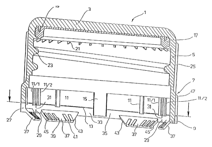
Fig, 1 shows a cross-section through a cap 1 before it is put onto
a to be closed container . The cap has a flat top 3 and a circumferent_ial
closed
casing 5. In the bottom edge part 7 of the casing 5 a guarantee area
is provided, in this case in the form of a guarantee ring 9, which is
joined to the rest of the casing by tear-off webs 1I, the tear-off
webs bridging a predetermined breaking line 13 which is provided by
making a horizontal incision in the wall of the casing 5.
The predetermined breaking line 13 is furthermore bridged by a hold-
ing web 15 which extends practically over the entire height of the
guarantee ring 9. The tear-off webs 11 and the holding web 15 are -.
formed by material strips which are provided on the inside surface of
the casing and extend in the longitudinal direction of the cap. From
Figure 1 it can be noted that the tear-off webs are considerably
narrower than the holding web, which i~ in eacz'~nstance associa~°d
with a ring segment produced by the snapping open of the guarantee
ring 9.
On the underside of the flat top a seal 17 is provided, which is pre-
vented from moving relative to the flat top 3 or the caa ? by holding
cams 19 projecting into same. In addition several webs 21 are provid-
ed that emanate from the inside surface of the casing and hold the
=_ea? 17 ij its correct position. aft°r th°- c=p ? is put cn-o =
to be
,._Ose= C.~.ntainer, the seal engaged wW:~ the ~OLIi.h area ~rereQL anC
seals same.
On--~.he inside surface of the casing 5, screw threads 23 can be noted.
which mesh with a corresponding external thread on the outside of the
container.
On the outer surface oz the casing, ribs 25 are provided extending in
the axial direction, which improve the grip of the cap.
The wall 27 of the guarantee ring 9 has vertical incisions-29 which
do not extend over the entire height oz the guarantee ring. There
remains in each instance at least one bridging web 31, which forms a
connection between the end sections of the ring segments 33 separated
by the vertical incisions 29.
The bridging webs 31 can be formed in that during the making of the
vertical incisions 29, a knife provided with a groove is ssad, :~'ry=c11
leaves part of the wall 27 of the guarantee ring 9 intact. It is also
uossible to provide on the inside surface oz the guarantee ring 9, in
the area of the vertical incisions, a web which is offset to the in-
side and which, similar to the tear-off Webs and the holding web 15,
remains intact whea a cut with a specific depth is made.
:rom tae inside sur_ace 35 of the guarantee ring 9 emanate in this
:,-r 1 r o °n iTg pro °ct~'~Jns 37, i~7i~_C_~..
case slant_...g_y downwa_d xt__d_... 7~
a r a p r o v i d a d with reinsorcing ribs 3 9 at 'heir e-ids . which -
proceeding fran t'~e
ront a1 of the projections 37 taper down in the form of a ramp in
the direction of the iaside surface 35 of the guarantee ring °, and
a t 3i s t anc a fry this inside surface becc~rie integral with tie surface of
the projections 37. The front face of the reinforcing ribs 39 to-
gether with the front face of the projections 37 forms a common stop
surface.
The projections 37 are shaped such that they emanate from the inside
surface 35 of the guarantee ring at a distance from a holding web 15,
and on their side facing the holding web have slanting sides=43. The
sides 45 on the opposite side of the projections form a right angle
with the inside surface 35 of the guarantee ring 9. The distance of
these sides 45 to a directly adjacent vertical incision 29 is consi-
derably less than that to the adjacent holding web I5.
From Figure 1 it can be seen that in the direct vicinity of the ver-
tical incision 2S tear-off webs 11/1 and 11/2 are provi3au, whic~~
prevent an unintentional tearing off of the end sections of the ring
segments 33.
On the outside of the edge 7 of the casiag 5 recesses ~9 are provided,
a side edge of which can be seen in Figure 1.
Figure 2 shows a tep view onto a guarantee r=ng 9 cut o~= along the
_'_ne 1_-.. shown in F~~Lre 1.
ore ,~r i : a ~ o ha ~ o "c c~ ocari n t ~o
'~ir___ _ arts n igure_ _ and 2 ar_ t..._ am_, t__y hav_ b_.._ give...
same reference numerals, so that a detailed description thereo= can be
dispensed with.
2~.~~~~
Fro__ the top view according to Figure 2 one can note the cut-ofL
tear-off webs 11 as well as 11/1 and 11/2, and also the cut through
the holding webs 15.
The top view shows that with the exemplified embodiment illustrated
here, a guarantee ring 9 consists of three ring segments 33, each of
which is held by a holding web 15.
In the end sections of the ring segments V-shaped material recesses 49
can be seen, in the base of which the vertical incisions 29 are made.
A material Weakening demanded of the production process is weakened in
an accurately predetermined manner by the specific incision 29.
From the top view the grooves 47 provided in the outside surface of
the guarantee ring 9 can pe seen, which are arranged precisely there
where on the inside surface 35 of the guarantee ring 9 the holding
webs 15 are arranged. The width of the grooves 47 is greater than the
width oz the holding webs, which are arranged centrally in relation to
the groove.
From the top view according to Figure 2 it can clearly be seea that
t'ne te3r-Of= webs 11 and the holding webs 1~ consist of material
3eCL=Ons L~_~.at are OiCs°. raCl~al 1 y t0 t .°_ 1~5_C°,
so t~3t Cur_~C a
t.._
DeC=_=C hOr_~OnL3- C',~.t t~rOUgLl th° dal is 27 O'_ ''°
CuaranC°-°- r.
L~eI7 recall praCtiC31 1 ~ lntaC t .
-
2~~.~~~
In ~articuiar from the top view of Figure 2 it can be deduced that
the cap 1 or its guarantee ring 9 has several form elements which are
arranged on the outside or the inside surface of the guarantee ring
9. By using these form elements, one can ensure an accurate alignment
of the cap when making the vertical incisions 29. As form elements,
one can use the projections 37 or their sides 45 and 43. Also the
position of the holding webs 15 on the inside surface 35 of the
guarantee ring 9 can be used for the accurate alignment of -the cap.
Finally, the grooves 47 or V-shaped recesses 49 provided on the
outside surface of the guarantee ring 9 can be used for the exact
positioning of the cap when making the vertical incisions 29. From
all this it can be_seen that also on the outside surface of the cas-
ing 5 of the cap 1 projections or recesses can be provided for its
positioning.
In the following it is assumed that the grooves 47 provided on the
outside surface and the holding webs 15 which in these areas are
provided on the inside surface 35 of the cap 1, are used for tze
accurate alignment of the cap 1.
The apparatus for the production of the plastic cap illustrated in
Figures 1 and 2 will be exalained with re=erence to the sectional
>~
view c. Figure 3.
The tool 50 has a housing 51 that can be coupled to a drive which
produces a rotational and traaslatory movement of the housing 51.
With this, the tool 50 can rotate around the axis of rotation or
w
the ~Iongitudinal axis 53. A translatory movement takes place along
this axis.
The housing 51 is preferably cylindrical, in particular circular
cylindrical. It has a through-bore which serves to accommodate an
inside centring device 55.
On the right face of the housing 51 a holder 57 for an outside
centring device 59 is provided in a suitable recess.
The inside centring device 55 has a guide sleeve 61 which is placed
in the through-bore.5l. The guide sleeve 6I can be moved in the axial
direction inside the housing'5l against the force of a spring element
63 in the farm of a helical spring. The helical spring is supported
on suitable projections as well as on the guide sleeve 61 and also in
the through-bore of the housing 51. By means of a groove 65 provided
in the inside wall of the housing 51 and a spring 67 emanating from
the guide sleeve 61, a turning of the two elements relative to one
another is prevented.
inside the guide sleeve 61 a fixing device 65~_s provided, which
/.
comprises a pressure stamp 67 which penetrates the inside cents=ng
.:» ; r0 '~.~. t:,' = a ; :-rn,re i ~ i rhea :,~ i; r:o
I_.... .. anG 3 ... uS t ~IOCj 6 WIl_Ch .s anC~ Q S-....r t-- gL-.-~-
°eV° C_, e.~. by SCrewlng. .StIT7~Orted '-~s~de .he t'?rll5~.
blvC:S Oa .S
a helical spr?ng 71, Wh~Ch by means of a re5~_-ent fCrCe pushes tn°
pressure stamp 67~out of the face of the inside centring device 55.
-13 '
2~~~~
Tha--pressure stamp is held by a suitable bearing arrangement 73 in
such a way-that during a rotating movement of the tool 50 it is held
already by a small counter-force and will not turn along. The end of
the pressure stamp positioned inside the tool 50 is held by a bearing
arrangement 75 that co-operates with the helical spring 71, and which
in turn is fitted with a bearing 77 to ensure an end coupling of the
rotating movement of the tool 50.
The bearing arrangement 73 has an outside sleeve which by the co-
operation between groove and spring is held in the guide sleeve 61
in such a way that it will not rotate.
On the front of the inside centring device 55 which in Figure 3 is
positioned on the right, a form element 79 is provided, the outside
contour of which is adapted to the inside contour of a cap that must
be held, which is not shown here. With the exemplified embodiment
illustrated here, the outside contour of the form element 79 is made
such that, for example, the holding webs 15 of the cap illustrated in
Figures 1 and 2 are held by a corresponding groove 81 provided in the
outside surface of the form element 79.
a
The form element 79 is exchangeable, so that with the tocl 50 several
___=event shapes of C~pS C3n be held..
~he outside centring device 59 comprises a scanning element 85 which
is elastically moveable in the direction of the centre axis 53 against
1 Z
2
the~force of a spring element 83, The scanning element 85 comprises a
tracing pin 87, which scans the outside surface of the cap and is
designed in such a Way that it fits into the groove 47 provided in
this outside surface.
In the following further details will be provided of how the process
is performed and of the mode of operation of the apparatus:
A cap, as illustrated in Figures 1 and 2, is fed to the tool 50 with
the flat top 3 facing away from the face of the tool, so that when
the tool 50 approaches, the pressure stamp 67 will engage in the
inside of the cap.l and comes to rest against the inside surface of
the flat top 3.
To scan the outside contours of the cap 1, either the cap is made to
rotate in relation to the tool or, as shown here, the tool 50 is made
to rotate in relation to the cap 1.
In the neutral position of the tool, illustrated in Figure 3, the
_ i
pressure stamp 67 projects beyond the face of the inside centring
device 55, and the tracing pin 87 of the outside centring device 59
projects beyond the face thereof.
'AI~3°n Lra°_ tC01 aDDrOaCr'°s t he cap .~e 1 at
~°_r .s =l~~e~ '_n .L= hC! der
r --
by the coapressive force exerted by the pressure stamp, and is held
tzars in such a way that it cannot rotate. 3ecause of the rotating
i
' ~ 2~.~~~
of tTe tool 50, the tracing pin 87 of the outside centring device 59
now engages with the outside contour of the cap 1, until the tracing
pin 87 locks into the groove 47 provided in the outside surrace. The
holder of the cap is designed in such a way that the cap now turns
along synchronously with the tool 50 inside its holder,
By means of a suitable actuating device - not illustrated here - the
guide sleeve 61 is now displaced to the right in the direction of
the axis of rotation of the tool 53 against the force of the helical
spring 63, so that the inside centring device 55 or its form element
79 moves into the inside of the cap. Due to the stationary arrange=
meat between the outside centring device 59 and the inside centring
device 55, the inside centring device can engage in the inside con-
tour of the cap without any further re-adjustment.
It is, therefore, ensured that when the tracing pin 87 engages in the
groove 47 of the cap, the groove 81 oz the form element 79 coincides
with the holding web 15 of a cap. Naturally, with the present exempli-
tied embodiment three similar grooves 81 are provided on the outside
surface of the form element 79, so that when the inside centring de-
vice 55 is introduced into the inside oL the cap 1, the grooves 81
will take hold o= the holding webs 15.
ns~~e onr-:=~ i o i iai~o r~
C..~,._- deV_C.. S nCw ~L..~_'.d ~OrWa_... 50 Cai 'nC-~ t..~-°
ace of the form element 79 sinks onto the base of the cap, and the
latter is securely held in position. During this movemeat o~ the
_ /~ _
' ~~.1~
insi~3e centring device into the inside of the cap, the projections 37
are folded inwards, so that they are swivelled slantingly upwards in
the direction of the inside of the flat top 3. As a result thereof
the cap 1 is securely held in position on the form element 79 of
the inside centring device 55. After the inside centring device has
snapped in, the outside centring device moves up to free the outside
or casing surface of the cap for the cutting operation.
Now, with the aid of a cutting device, the predetermined breaking
line 13 can be provided in the edge part 7 of the casing 5 by means
of a horizontal cut, the depth of the cut being adapted to the thick-
ness of the wall 27 in such a way that the knife does not or not
significantly damage the inwardly offset tear-off webs 11 and the
holding webs 15.
The outside surface of the form element 79 is designed in such a
way that at the same time it serves as an abutment for the cutting
device, during the making of the horizontal as well as the vertical
incisions.
aster making the horizontal incision, because of its orientation on
to inside centring device 55, the cap 1 can be fed to the cutting
device _n a predetermined position, so that the curt=ng dsvice can
;= ; ' 20 ;~ a ~i - ~~s guarantee
~CW make the vertical _ c_s~ons th wa__ 27 e.
ring 9. The drive of the tool 50 is~designed such that it can be
moved towards the knife of the cutting device in an exact orienta-
tion.
_u ,
2~~~~a~
From all this it can be seen that because of the interplay between
the outside centring device 59 and the inside centring device 55 an
accurate position orientation of the cap 1 can be obtained, so that
the incisions required to split the guarantee ring 9 into ring seg-
ments can be made with great precision.
Because a relative rotation between the outside centring device 59
connected rigidly to the sleeve 51 and the guide sleeve 61--of the
inside centring device 55 is not possible, the inside centring device
or its form element 79, after scanning the outside contour with the
aid of the tracing pin 87, can without problem be introduced into~the
inside of the cap,. during which the orientation of the cap is main-
tained.
The neutral position of the tool 50 illustrated in Figure ~, in which
i
the pressure stamp 67 of the fixing device 65 projects beyond the face
of the form element 79 together with the tracing pin 87, ensures that
at first the cap 1 is securely held in position in its holder by the
pressure stamp, whilst the tracing pin 87 which rotates together with
the tool 50 scans the outside contours of the cap 1. As soon as the
tracing pin 87 locks into the associated groove 47, the driving force
o= the tool 50 becomes so great that the cap is made to rotate inside
t or 'w i~u w~t~3 L~e t001 . ~.n t~~.~5 i'1a~ t=° 1n5=d°-
C~°
,... c_d~ ~..get__r
deVr.C° C5n be securely lntrOduCed lnLO tie CO-rOtat3.ng Cap. ~n
th°~
'nd position, in which the inside centring device 55 is moved out
completely by the forward movement of the guide sleeve 6I, the inside
2~~.~~v
centring device projects beyond the face oz the pressure stamp as
well as beyond the tracing pin of the outside centring device 59, so
that a displacement of the cap by the tool itself need now no longer
be feared. Furthermore, this forward movement of the inside centring
device 55 ensures that during the making of the horizontal incision
to produce the predetermined breaking line 13 or during the making of
the vertical incisions 29 that extend in the longitudinal direction,
the cutting device will not come in contact with the outside-,.centring
device. This prevents damages to the cutting device as well as to the
tool 50.
If during the making oz the vertical incisions 29 one does not use a
knife with a groove, by which the areas or webs 31 that bridge the
vertical incisions remain intact, it is also possible to use a knife
with a continuous cutting edge if on tue inside surface 35 of the
guarantee ring 9, the same as with the tear-off webs 11 and the hold-
ing webs 15, radially inwardly offset material sections are provided
which remain intact or at least remain substantially uncut when mak-
ing the cut with a specific depth.
To increase the effectiveness of the apparatus or the production
process, the tool 50 may be placed in a machining star, to which the
to be mach =nod caps are =ed in the known marnsr .,
F~om all this it can readily be seen that the producticn process and
the apparatus can be used irrespective o~ which outside or inside
17
21.~~~~~
contours are used for the scanning when making the vertical incisions
in the cap. A11 that is required is that the relative arrangement of
the scanned contours or form characteristics to the position of the
to be provided vertical incisions is known, so that the bringing
together of the tool 50 and the cutting device, which is not shown
here, can be arranged in such a way that the vertical incisions can
be made in the desired, predetermined gosition. They may, for exam-
ple, be positioned in the end sections of two adjacent ring segments
33, so that these end sections are held by the tear-off webs 11/1 and
11/2, in which case the cut of the vertical incisions 29 is preferab-
ly made in the base of the V-shaped recess 49. In this way relatively
little material needs to be cut, so that the Life of the knives is
increased considerably.
With the construction of the tool 50 described here or the performing
of the production process in the manner described here, it is ensured
that the vertical incisions 29 are arranged in the immediate vicinity
between the sides 45 of the projections 37 that taper down perpendi-
cularly to the inside surface 35, where during a first opening of the
cap the maximum force is introduced into the guarantee ring. There-
.ore, also if the vertical incisions have a certain strength as a
esul~. o. the bridging webs 31, it is ensured that during the first
t'empv a. Cpe .'~''' a r~ a ~~ ee
L' ..g th C3p 1 , CIIa_ nt "1ng 9 O. t~e C~~ _ w=_~
slap cpen. ~vnen th~.s happens, the prOJeCL~OnS 37 i.~8i. cC~ as ~cT_'~r~.5
will d;g in under the mentioned DrO~eCt'_On On th°- Outslae O.
t~°_
container and will produce axial and radial expansion forces on the
~a°~ 2~.~.~~~
guarantee ring, so that same will snap open. With the exemplified
embodiment illustrated in the figures, the holding webs lie in the
rotation and swivel point of the ring segments 33 and remain intact
during the snapping open of the guarantee ring. They are made so
strong that they hold the snapped open ring segments in the swivelled
position, so that the consumer can readily see that the cap has been
interfered with.
Finally, it must still be mentioned that in individual,fields of
application, where the positioning of the vertical incisions is less
critical, the outside centring can be dispensed with. In this case
the inside centring device 55 is moved against the cap fixed in
position by a holder until the form element 79 locks into the given
inside contours of the cap and securely holds same./
From what has been mentioned above, it can readily be noted that in a
plastic cap, which may be made, for example, by an injection moulding
or compression moulding process, subsequently a vertical incision can
be provided in an exactly predetermined spot. The positioning of the
vertica_ incision depends here on the form characteristics provided
on the inside and/or outside of the cap, which can be scanned with
the a=d o. a suitable device.
;yilSi~ .~'~.aK=ng t-he ~e~ L~ Cal ~nC' S~C~ . _ '_S CL. L° boss' bie
LC iu t pr0-
wide a guarantee area that does not extend over the entire periphery
at the bottom edge of the casing, but is associated, for example,
with an arc-shaped circumferential area which has an opening angle
-am 2~~~~
of 60 to 240', preferably of 180' or 120'. The vertical incision is
preferably placed in the middle of such a guarantee area, i.e. in
an area which during the first opening of the cap is subjected to
a maximum axial and radial displacement. In this way it is ensured
that the vertical incision will snap open during the first opening,
so that the consumer can readily note that the cap has been inter-
feted with. The end sections of such a guarantee area are fixed to
the rest of the casing. In this case no holding webs are required
which hold the segments after the snapping open of the vertical in-
cision. Here, the segments are joined by way of their end sections
to the rest of the cap and cannot get lost.
An important aspect is that the vertical incisions can be made at
a later stage in pre-manufactured plastic caps, and in doing so an
accurately predetermined positioning is maintained, so t~~a~ deforma-
Lions that occur during the first opening of the cap are introduced
exactly into the vertical incision.
Naturally, it is also possible to make caps that have two guarantee
areas which snap open into segments during the first opening, which
secments are in turn held by holding webs. Finally, as illustrated by
he ~icures, it is also possible to make a cap with several guarantee
_ _ng segmen'-n di s tr ibuted over t he peri phery o. t he bo t tcm =dge ,
and
which segments =orm an all-round guarantee r_ng.
finally, the making of the vertical incisions can take place indepen-
gently of the special shape of the form characteristics used for the
_~a_
_ ~1~~~~:~
positioning. The exact arrangement of the vertical incisions can
at any rate be maintained, wherein the form characteristics may be
arranged on the inside and/or on the outside of the cap.
Because of the described, exact positioning of the vertical inci-
sions, when producing same, the making of a horizontal incision -
extending over a circumferential area or along the entire periphery -
by which the guarantee area or a guarantee ring is formed, can take
place in an independent, autonomous process step. It is possible, in
particular, to use completely separate cutting devices for making the
two incisions (horizontal incision and vertical incision), so that
the requirements on the cutting device can be relatively low and same
can be produced economically.
it has been found that especially with the particularly stable design
of the projections 37, with the aid of reinforcing ribs 39 provided
at the top thereof, very high snapping open forces can be introduced
into the vertical incisions. By the combination of an exact position-
ing of the vertical incisions and the introduction of particularly
high snapping open forces into the areas provided with vertical inci-
sions, an extremely high operational reliability 1.5 obtained, based
which any interference with the cap will with a particularly great
C°_r ta'=t_T lead t0 a snaT7D~ng Open O. tr'° Ver:_C31
=r'Cis=C'?S, So tar
-=,o a t, r '~on Ty ~ r "e ~ or "'-. =! ~ 'l C_OSeO CJ.~_t2_ne. .
._ cm...~e_ ,.,.._. secu_ -y ecogn_~ a _7-