Language selection

Search

Patent 2112635 Summary

Third-party information liability

Some of the information on this Web page has been provided by external sources. The Government of Canada is not responsible for the accuracy, reliability or currency of the information supplied by external sources. Users wishing to rely upon this information should consult directly with the source of the information. Content provided by external sources is not subject to official languages, privacy and accessibility requirements.

Claims and Abstract availability

Any discrepancies in the text and image of the Claims and Abstract are due to differing posting times. Text of the Claims and Abstract are posted:

  • At the time the application is open to public inspection;
  • At the time of issue of the patent (grant).
(12) Patent: (11) CA 2112635
(54) English Title: DISHWASHER CONVECTION AIR INLET AND SUDS CONTROL DEVICE
(54) French Title: DISPOSITIF D'ADMISSION D'AIR DE CONVECTION ET EVACUATEUR DE MOUSSE POUR LAVE-VAISSELLE
Status: Deemed expired
Bibliographic Data
(51) International Patent Classification (IPC):
  • A47L 15/44 (2006.01)
  • A47L 15/48 (2006.01)
(72) Inventors :
  • TULLER, BARRY E. (United States of America)
  • JOHNSON, THOMAS M. (United States of America)
(73) Owners :
  • MAYTAG CORPORATION (United States of America)
(71) Applicants :
(74) Agent: FINLAYSON & SINGLEHURST
(74) Associate agent:
(45) Issued: 1996-02-13
(22) Filed Date: 1993-12-30
(41) Open to Public Inspection: 1994-08-20
Examination requested: 1995-03-22
Availability of licence: N/A
(25) Language of filing: English

Patent Cooperation Treaty (PCT): No

(30) Application Priority Data:
Application No. Country/Territory Date
08/019,763 United States of America 1993-02-19

Abstracts

English Abstract


A convection air inlet and suds control device is
provided for a dishwasher. The dishwasher has a
washing chamber with a bottom wall, and a chimney
extending through the bottom wall with opposite upper
and lower ends positioned on opposite sides of the
bottom wall. A chimney cap is spaced in covering
relation over the upper end of the chimney. A
container having an inner cup and an outer cup is
mounted adjacent the bottom wall such that the inner
cup surrounds the lower extension of the chimeny. The
outer cup includes an opening such that air may flow by
convection into the outer cup, into the inner cup and
upwardly through the chimney into the washing chamber
so as to dry the articles in the dishwasher. In
oversudsing conditions, the suds flow downwardly
through the chimney for collection in the inner cup.
Excess suds filling the inner cup will spill over into
the outer cup. The inner cup and lower extension of
the chimney cooperate to function as a valve. When
liquid deriving from condensing suds in the inner cup
rises to a level above the lower end of the chimney,
downward flow of suds into the inner cup and upward
flow of air through the chimney is prevented. As the
liquid evaporates to a level below the lower end of the
chimney, the flow of air and suds returns to normal.


Claims

Note: Claims are shown in the official language in which they were submitted.


The embodiments of the invention in which an
exclusive property or privilege is claimed are defined
as follows:
1.
An air inlet and suds control device for a
dishwasher having a washing chamber with a bottom
wall, a chimney extending through the bottom wall
with opposite upper and lower open ends positioned on
opposite sides of the bottom wall, and a chimney cap
spaced in covering relation over the upper end of the
chimney, the device comprising:
a receptacle mounted below the bottom wall of the
washing chamber and being positioned underneath
the lower end of the chimney so as to receive suds
entering the upper end of the chimney and flowing
downwardly through the chimney;
the receptacle being open to the atmosphere such that
air may flow by convection into the receptacle and
upwardly through the chimney and into the washing
chamber.
2.
The device of claim 1 wherein the receptacle has
a sidewall with an open upper end and a closed lower
end, the sidewall having at least one opening therein
for the convection flow of air into the receptacle.


- 10 -


3.

The device of claim 2 wherein the receptacle
includes an inner cup positioned underneath the
chimney so as to receive suds passing downwardly
through the chimney.
4.
The device of claim 3 wherein the inner cup has
an open upper end positioned below the upper end of
the receptacle, whereby suds overfilling the inner
cup will overflow into the receptacle.
5.
The device of claim 1 wherein the receptacle includes
a large chamber and a small chamber positioned within
the large chamber, the small chamber being underneath
the chimney so as to receive suds flowing downwardly
therethrough, and such that suds overflowing the
small chamber are received in the large chamber.
6.
The device of claim 1 further comprising an
inlet tube extending downwardly from the chimney and
having a lower end extending into the receptacle,
such that the inlet tube allows air to flow by
convection upwardly therethrough until such time that
liquid resulting from condensing suds in the
receptacle rises to a level in the receptacle above
the lower end of the inlet tube.


- 11 -


7.

The device of claim 6 wherein the inlet tube
extends above the chimney and terminates in an open
upper end, the inlet tube having a splash guard
extending radially outwardly therefrom at a position
above the upper end of the chimney, so as to minimize
splashing of wash water into the inlet tube.
8.
The device of claim 6 wherein the chimney cap is
cup-shaped and has a wall defining interior and
exterior perimeter surfaces, and the inlet tube has a
plurality of fingers extending upwardly from the
upper end thereof so as to substantially matingly
engage with the interior perimeter surface of the
cap.
9.
An air inlet for a dishwasher having a washing
chamber with a bottom wall, the dishwasher washing
chamber including a chimney with portions extending
upwardly and downwardly through the bottom wall and
terminating in open upper and lower ends, and a
chimney cover spaced in covering relationship over
the upper end of the chimney, the air inlet
comprising:


- 12 -


a first container surrounding the downwardly
extending portion of the chimney and including a
bottom wall spaced below the open lower end of
the chimney, the upper periphery of the first
container being substantially open to
atmosphere; and
a second container substantially surrounding the
first container, the second container being
mounted to the washing chamber bottom wall and
including a side wall having an open portion
defining an air flow path for atmospheric air to
convectively enter the second container, the
first container, the chimney and the washing
chamber to effect the drying of dishes.
10.
The air inlet of claim 9 wherein the first and
second containers each have an upper end, the upper
end of the first container being at a lower elevation
than the upper end of the second container, whereby
suds flowing from the washing chamber and into the
chimney will be received in the first container until
the first container is filled, and the suds will
spill over the upper end of the first container into
the second container.


- 13 -


11.
The air inlet of claim 10 wherein the lower end
of the chimney defines a normally open valve allowing
air to flow by convection upwardly through the
chimney and allowing suds to flow downwardly into the
first container, the valve being closed to prevent
flow in either the upward or downward direction when
liquid deriving from suds condensing in the first
container rises to a level above the lower end of the
chimney.
12.
A suds suppressing air inlet for a dishwasher
having a washing chamber with a bottom wall, the
dishwasher washing chamber including a chimney with
portions extending upwardly and downwardly through
the bottom wall and terminating in open upper and
lower ends respectively, and a chimney cover spaced
in covering relation over the open upper end of the
chimney, the air inlet comprising:
an outer cup surrounding the downwardly extending
portion of the chimney and adjacent to said
bottom wall, the outer cup including a side wall
having an opening to atmosphere for permitting
air to enter the chimney;


- 14 -


an inner cup surrounded by the outer cup and having
an open top spaced below the washing chamber
bottom wall, the inner cup enclosing the
downwardly extending portion of the chimney and
including a bottom wall spaced below the open
lower end of the chimney, the air inlet defining
a flow path for suds escaping from the washing
chamber in an oversudsing condition, the inner
cup providing surface contact area for
condensing suds into liquid to bridge the space
between the inner cup bottom wall and the open
lower end of the chimney for stopping the flow
of suds from the washing chamber.
13.
The air inlet of claim 12 wherein the inner and
outer cups each have an upper end, the upper end of
the inner cup being at a lower elevation than the
upper end of the outer cup, whereby suds flowing from
the washing chamber and into the chimney will be
received in the inner cup until the inner cup is
filled, and the suds will spill over the upper end of
the inner cup into the outer cup.
- 15 -

Description

Note: Descriptions are shown in the official language in which they were submitted.


2 1 1 2635
DISHWASHER CONVECTION AIR INLET AND SUDS CONTROL DEVICE


BACKGROUN~ OF THE INYENTION
~any dishwashers utillze a convection air system
for drying the dishes, glasses, cups, utensils and
the like that are washed within the washing chamber.
For mA~imum efflc ency, the air inlet for the drying
system is normally located at the lowest location in
the washing chamber. However, placement of the air
inlet at such a location exposes the inlet to water
splashing and sudsing. Suds, or foam, can be caused
from combinations of food soils and detergents, or by
use of a laundry or low grade dishwasher detergent.
Suds in the washing chamber can accumulate to a depth
of nearly one foot, and will be forced through any
openings in the lower portion of the washing chamber.

SUMNA~Y OF THE INVENTION
A primary objective of the present invéntion is
to provide an i~proved dishwasher convection air
inlet.
Another objective of the present invention is
the provision of a dishwasher suds control device.
Still another objective of the present invention
is the provision of a dual purpose dishwasher
convection air inlet and suds control device.
A further objective of the present invention is
the provision of a dishwasher convection air inlet
which can be retrofit to an existing washing chamber.


635
Still a further objective of the present
invention is the provision of a container for
receiving excessive suds Erom the washing chamber.
Ano'~her objective of the present inventlon is
the provision of a dishwasher convection air inlet
and suds control device which allows air to flow
convectively upwardly through the chimney in the
washing chamber and which allows suds to flow
downwardly through the chimney into a collection cup.
The present invention achieves these obiectives
in a convection air inlet and suds control device for
a dishwasher having a washing chamber with a bottom
wall. The dishwasher also includes a chimney
extending through the bottom wall with opposite upper
and lower ends positioned on opposite sides of the
bottom wall. A chimney cap is spaced in covering
relation over the upper end of the chimney.
The device includes a large outer container
attached to the bottom wall of the dishwashing
chamber below the chimney. The outer container has a
sidewall with at least one opening therein for
permitting air to flow by convection into the outer
container and upwardly throuah the chimney. An inner
container is positioned within the outer container
and underneath the chimney so as to enclose the
downwardly extending lower end of the chimney. The

21 1 2635
upper end of the inner container is below the upper
end of the outer container. When the washing chamber
is in an oversudsing condition, suds flow downwardly
through the chimney into the inner container. AS the
inner container fills with suds, the suds spill over
the upper end of the inner container into the outer
container. The suds condense in the inner container
and change to liquid. When the liquid level rises to
an elevation slightly above the lower end of the
chimney, downward flow of suds and upper flow of air
will be stopped until the liquid evaporates to an
elevation below the lower end of the chimney.

DESCRIPTION OF THE DRAWINGS
Figure 1 is a perspective view of a dishwasher
having the door in an open position.
Figure 2 is a sectional view taken along lines
2-2 of Figure 1.
Figure 3 is a sectional view taken along lines
3-3 of Figure 2, showing the air inlet and suds
control device of the present invention.
Figure 4 is a sectional view taken along lines
4-4 of Figure 2 and shown out of order along with
Figure 1.
Figure 5 is a sectional view taken along lines
5-5 of Figure 4.


21 1 2635
Figure 6 is an exploded pérspective view of the
air inlet and suds control device of the present
invention.

DESCRIPTION OF PREFERRED E~BODI~ENT
Referring to the dra~Tings, the reference numeral
lO generally designates a dishwasher. The dishwasher
has a washing chamber or tub 12 defined by opposite
side walls 14, a top wall (not shown~, a bottom wall
16, a back wall 18, and a door 20. A rotating water
spray arm 22 i5 operatively mounted in the bottom of
the washing chamber 12.
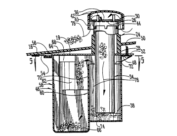
As best seen in Figures 3 and 4, a chimney 24
extends through the bottom wall 16. The chimney 24
includes an open upper end 26 located above the
lS bottom wall 16 and an open lower end 28 located below
the bottom wall. A chimney cap or cover 30 is in
spaced covering relation over the upper end 26 of the
chimney 24. The cap 30 includes a tab 32 for
securing the cap to the bottom wall 16 of the washing
chamber 12 with a screw (not shown).
An inlet tube 34 defines a chimney extension.
The upper end 36 of the tube 34 is positioned above
the upper end 26 of the chimney 24, and the lower end
38 of the tube 34 is positioned below the lower end
28 of the chimney 24. The upper end 36 of the inlet


21 1 2635
tube 34 includes a flange or splash guard 40
extending radially outwardly therefrom so as to
minimize the entry of splashing water into the inlet
tube 34. ~ p~urality of ~paced apart fingers 42
extend upwardly from the perimeter edge of the splash
guard 40 so as to register with the inner peripheral
surface of the chimney cap 30, as best seen in Figure
4. Annular flange 44 extends downwardly from the
splash guard 40 for positioning the inlet tube 34
over the upper end 26 of the chimney 24.
It is understood that the inlet tube 34 is
provided as a retrofit component to provide a chimney
extension on current chimney designs. Alternatively,
the chimney could be redesigned and manufactured with
at least the lower extension effectively equivalent
to the lower end 38 of the inlet tube 34.
A receptacle or cGntainer 46 is mounted to the
bottom wall 16 of the washing chamber 12 so as to be
located under the chimney 24. The container 46
includes a first tab 48 having a hole for receiving a
screw 50 which is threadably received in a portion or
extension 52 of the tub support 19, as seen in Figure
4. A second tab 54 is provided on the container 46
for receipt in a slot 56 in the portion 52 of the tub
support 19.


21 1 2635
The container 46 includes a large outer cup 58
with a smaller inner cup 60 mounted therein. The
outer cup 58 includes a side wall 62 with an upper
end 64 and a bottom wall 66. At least one opening 68
is provided in the side wall 52 such that the outer
cup 58 is open to the atmosphere whereby air may flow
by convection into the outer cup 58, into inner cup
60 and upwardly through the chimney extension defined
by the inlet tube 34 and thus into the washing
chamber 12. The inner cup 60 includes a side wall 70
with an upper end 72 and a bottom wall 74. The upper
end 72 of the inner cup is below the upper end 64 of
the outer cup 58, as seen in Figures 4 and 6. The
side wall 70 of the inner cup 60 surrounds the inlet
tube 34, with the bottom wall 74 of the inner cup 60
being spaced below the lower end 38 of the inlet tube
34, as seen in Figure 4.
During the drying cycle of the dishwasher
operation, air flows by convection into the opening
68 in the outer cup 58, into the inner cup 60 and
then upwardly through the inlet tube 34 and chimney
24 for entry into the washing chamber 12 so as to
effect drying of the articles contained in ~he
dishwasher 10. The flow of air is represented by
arrows 76 in Figure 3.


21 1 2635
5uring operation of the dishwasher, if an
oversudsing condition is encountered, suds may rise
above the upper end of the chimney extension inlet
tube 34 so as to flow downwardly through the tube 34.
The suds are recelved in the inner cup 60. If the
suds fill the inner cup 50, excess suds will spill
over the upper end 72 of the inner cup 60 and into
the outer cup 58. The suds flow is represented by
arrows 78 in Figure 4. Since the suds contain a high
lQ percentage of water, condensation of the suds creates
a liquid level n the bottom of the inner cup 60. If
the liquid level rises to an elevation slightly above
the lower end 38 of the inlet tube 34, the flow of
suds into the inner cup 60 is stopped due to the
water pressure. Thus, the inner cup 60 and the lower
end 38 of the inlet tube 34 cooperate to form a valve
to control the flow of suds. Eventually, the liquid
in the inner cup 60 will evaporate such that the flow
of suds into the inner cup 60 can resume. Suds
spilling over into the outer cup 58 will also
condense into liquid, which will ultimately
evaporate.
When the liquid level in the inner cup 60 is
above the lower end 38 of the inlet tube 34, air flow
into the inlet tube 34 and the chimney 24 is also
prevented. Once the liquid evaporates, the


21 1 2635
convection drying operation will return to normal.
Alternatively, a weep hole (not shown) may be
provided in the inner cup 60 to slowly bleed off the
liquid i~ltO the outer C'lp 58 SO as to allow for
normal drying operation, w~thout any shut-off valve
effect created by liquid in the inner cup 60.
The preferred embodiment of the invention has
been set forth in the drawings and the specification,
and although specific terms are employed, these are
used in a generic or descriptive sense only and are
not used for purposes of limitation. Changes in the
form and proportion of parts as well as in the
substitution of equivalents are contemplated as
circumstances may sugsest or render expedient without
departing from the spirit or scope of the invention
as further defined in the following claims.
From the foregoina, it can be seen that the
present invention accomplishes at least all of the
stated objectives.

Representative Drawing
A single figure which represents the drawing illustrating the invention.
Administrative Status

For a clearer understanding of the status of the application/patent presented on this page, the site Disclaimer , as well as the definitions for Patent , Administrative Status , Maintenance Fee  and Payment History  should be consulted.

Administrative Status

Title Date
Forecasted Issue Date 1996-02-13
(22) Filed 1993-12-30
(41) Open to Public Inspection 1994-08-20
Examination Requested 1995-03-22
(45) Issued 1996-02-13
Deemed Expired 2007-01-02

Abandonment History

There is no abandonment history.

Payment History

Fee Type Anniversary Year Due Date Amount Paid Paid Date
Application Fee $0.00 1993-12-30
Registration of a document - section 124 $0.00 1994-07-15
Maintenance Fee - Application - New Act 2 1996-01-01 $100.00 1995-08-17
Maintenance Fee - Patent - New Act 3 1996-12-30 $100.00 1996-08-06
Maintenance Fee - Patent - New Act 4 1997-12-30 $100.00 1997-12-29
Maintenance Fee - Patent - New Act 5 1998-12-30 $150.00 1998-09-28
Maintenance Fee - Patent - New Act 6 1999-12-30 $150.00 1999-07-30
Maintenance Fee - Patent - New Act 7 2001-01-01 $150.00 2000-09-25
Maintenance Fee - Patent - New Act 8 2001-12-31 $150.00 2001-08-08
Maintenance Fee - Patent - New Act 9 2002-12-30 $150.00 2002-08-09
Maintenance Fee - Patent - New Act 10 2003-12-30 $200.00 2003-08-19
Maintenance Fee - Patent - New Act 11 2004-12-30 $250.00 2004-09-17
Owners on Record

Note: Records showing the ownership history in alphabetical order.

Current Owners on Record
MAYTAG CORPORATION
Past Owners on Record
JOHNSON, THOMAS M.
TULLER, BARRY E.
Past Owners that do not appear in the "Owners on Record" listing will appear in other documentation within the application.
Documents

To view selected files, please enter reCAPTCHA code :


To view images, click a link in the Document Description column. To download the documents, select one or more checkboxes in the first column and then click the "Download Selected in PDF format (Zip Archive)" or the "Download Selected as Single PDF" button.

List of published and non-published patent-specific documents on the CPD .

If you have any difficulty accessing content, you can call the Client Service Centre at 1-866-997-1936 or send them an e-mail at CIPO Client Service Centre.


Document
Description 
Date
(yyyy-mm-dd) 
Number of pages   Size of Image (KB) 
Cover Page 1995-04-08 1 49
Abstract 1995-04-08 1 61
Claims 1995-04-08 6 307
Drawings 1995-04-08 3 214
Description 1995-04-08 8 471
Cover Page 1996-02-13 1 17
Abstract 1996-02-13 1 38
Description 1996-02-13 8 245
Claims 1996-02-13 6 163
Drawings 1996-02-13 3 130
Representative Drawing 1998-03-26 1 19
Prosecution Correspondence 1995-03-22 1 48
Prosecution Correspondence 1995-03-22 3 74
Office Letter 1995-04-26 1 21
PCT Correspondence 1995-12-04 1 33
Fees 1995-08-17 1 56
Fees 1996-08-06 1 51