Language selection

Search

Patent 2112741 Summary

Third-party information liability

Some of the information on this Web page has been provided by external sources. The Government of Canada is not responsible for the accuracy, reliability or currency of the information supplied by external sources. Users wishing to rely upon this information should consult directly with the source of the information. Content provided by external sources is not subject to official languages, privacy and accessibility requirements.

Claims and Abstract availability

Any discrepancies in the text and image of the Claims and Abstract are due to differing posting times. Text of the Claims and Abstract are posted:

  • At the time the application is open to public inspection;
  • At the time of issue of the patent (grant).
(12) Patent Application: (11) CA 2112741
(54) English Title: A METHOD OF INSTALLING A SOIL ANCHOR AND A SOIL ANCHOR
(54) French Title: METHODE D'INSTALLATION D'UN ANCRAGE DANS LE SOL, ET ANCRAGE
Status: Deemed Abandoned and Beyond the Period of Reinstatement - Pending Response to Notice of Disregarded Communication
Bibliographic Data
(51) International Patent Classification (IPC):
  • E02D 05/74 (2006.01)
  • E02D 05/76 (2006.01)
  • E02D 05/80 (2006.01)
(72) Inventors :
  • SKOGBERG, BO TORBJORN (Sweden)
(73) Owners :
  • SOILEX AB
(71) Applicants :
  • SOILEX AB (Sweden)
(74) Agent: BERESKIN & PARR LLP/S.E.N.C.R.L.,S.R.L.
(74) Associate agent:
(45) Issued:
(86) PCT Filing Date: 1992-07-01
(87) Open to Public Inspection: 1993-01-21
Examination requested: 1999-05-31
Availability of licence: N/A
Dedicated to the Public: N/A
(25) Language of filing: English

Patent Cooperation Treaty (PCT): Yes
(86) PCT Filing Number: PCT/SE1992/000508
(87) International Publication Number: SE1992000508
(85) National Entry: 1993-12-31

(30) Application Priority Data:
Application No. Country/Territory Date
9102054.5 (Sweden) 1991-07-01

Abstracts

English Abstract

2112741 9301360 PCTABS00019
A soil anchor body (11) of folded sheet steel is hammered down
into the soil by means of a rock drill rig. It carries with it a
hose (19) coupled to its rear end and one or more steel ropes (29)
deviated over its front end. The drill rod is withdrawn and
cement grout is injected through the hose into the anchor body to
inflate it. The steel ropes are now anchored and both ends of each
rope are above ground and ready to be used to take tension load. If
the soil anchor is only temporary used, the steel ropes can be
withdrawn simply by being pulled at one end.


Claims

Note: Claims are shown in the official language in which they were submitted.

WO 93/01360 PCT/SE92/00508
Claims
1. A method of installing a soil anchor by driving down an inflatable
anchor body (11) of folded metal sheet into the ground by means of a rod
and then pressurizing the body to develop the folds and expand the body,
characterized by the steps of
coupling a tension line (29) and a pressure hose (19) to the anchor body
(11) so that the anchor body takes them with it into the ground,
withdrawing the rod, expanding the anchor body by pressurizing it
through the hose, and tensioning the line.
2. A method according to claim 1, characterized by coupling the line
(29) to the anchor body (11) outside of the body.
3. A method according to claim 2, characterized by deviating the line
(29) about the front end of the anchor body (11) to couple it to the
anchor body so that there will be two ends of the line above ground.
4. A method according to claim 3, characterized by coupling two or more
lines (29) in parallell to the anchor body (11).
5. A method according to claim 3 or 4, characterized by mounting a bow-
formed line support (22) on the front end of the anchor body (11) and
deviating the line (29) about the support.
6. A method according to any one of claims 3 to 5 for installing a
temporary soil anchor, characterized by the step of pulling one end of
the line (29) to get the line out of the ground when the anchor has
been used.
7. A metod according to any one of claims 2 to 6 for installing a
temporary soil anchor, characterized by coupling at least two lines (29)
to a yoke (40) and mounting the yoke on the front end of the anchor body
(11) and pulling up the yoke by pulling one of the lines to release the
yoke from the anchor body when the anchor has been used.

WO 93/01360 PCT/SE92/00508
8. A method according to claim 7, characterized by mounting three lines
(29) to the yoke (40).
9. A method according to any one of the preceding claims, characterized
by hammering down the anchor body (11) by hammering on the rod (17)
which is an extension rod, for example a conventional rock drill
extension rod.
10. An inflatable soil anchor body (11) made of folded sheet metal that
is sealed in both ends and has an inlet (18) for pressure fluid at its
rear end,
characterized by a bow-formed support (22) for a steel rope (29) at its
front end, said support permitting the rope to slide therein.

Description

Note: Descriptions are shown in the official language in which they were submitted.


W 0 93/01360 2 1 12 7 41 P ~ /SE92/00508
A METHOD OF INSTALLI~G A SOIL ANCHOR A~D A SOIL ANCHOR.
Thls lnvention relates to a method o lnst~llln~ a soll anchor by drlv1ng
down an expanslble anchor body of folded metal sheet lnto the ~round by
me~n~ of a rod or tube ~nd then prec6urlzlng the body to develop the
folds and expand the body. It al~-o rel~tes to ~n anchor body.
An ~nchor body ~nd ~ method of thl~ klnd ~re descrlbed ln FP 0112316-A.In pr~ctlce, ~ tube ls u6ed for drivlng down the anchor body and then lt
16 u6ed for lnJectlng cement grout lnto the nnchor body to exp~nd the
body. One or re reinforclng rods or ctlff 6teel rope~ or the llke ~re
forced down through the tube ~nd lnto the ~nchor body ~nd theynre then
used to tnke the ten610n lo~d. Thl~ ~ethod lc belng used and lt ls
out6tanding.
It $6, however, ~ dl6ndv~ntage that the ~nchor cannot be u6ed untll thece~ent grout h~ h~rdened whlch take6 d~ys or ~1~06t a week. It 16 ~lso
so~etl~e6 ~ dl6Adv~ntage that the tube wlth lt6 tenslon lo~d c~rrylng
ela~ent6 wlll rem~ln ln the soll nnd th~t lt c~nnot be dug up wlthout
flr6t belng cut lnto plece6.
It 1~ nn obJect of the lnventlon to m~e an ~nchor of thls klnd le s
c06tly and to m~ke posclble the use of an nnchor nlmost lmmedlntly lt
h~s been ln6talled. It 16 nlso nn ob~ect to nnke lt posslble to take up
the ~nchor except for the nnchor body f~t ~nd e~slly.
The lnventlon wlll be descrlbed wlth reference to the dr~wlngs.
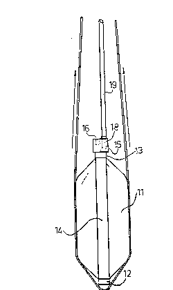
Flg l 6hows ~n anchor whlle drlven lnto the soll
~lg 2 6hows the &~me anchor exp~nded
Flg 3 ~how6 the 6ame nnchor whlle belng dl6~0unted
Flg 4 6hows enl~rged the front end of the ~nchor shown ln Flgs 1-3
Plg 5 ls ~ ectlon along the llne~ 5-5 ln Flg 4

W O 93/01360 PCT/SE92/00508
2 1 1 ~ 7 ~ 1 2
In Flgs 1-3, an expanslble anchor body 11 ls shown.It ls generally of
the klnd descrlbed ln EP-0112316-A and wlll therefore not be descrlbed
ln det~ll but EP-0112316-A ls lncorpor~ted by way of reference. The
~nchor body 11 ls made of two steel sheets that are welded together
~ ong thelr longltudinal edges and folded ln a zig zag form so that they
form a cylindrical pole with rectangular or qu~dr~tlc cross ~ection(F~g
1). A cup 12 covers ~nd ~eals the front end of the pole and an annular
cup 13 surrounds the re~r upper end of the pole. Pour flats 14 are
welded to the cups 12,13. There ls a sealln~ vlscos agentt for example
~sph~lt, in the cups 12,13 ~nd the cup~ are held together by the flnts
14. A solld ~teel block 15 ls welded to the re~r cup 13 and it h~s a
.~ ~ bllnd bore 16 for the-end of a rock drlll exteDsion rod 17 and a bore 18
wlth ~ flttln~ for ~ hose l9. The bore 18 ends ln the center of the
~nnular cup 13, thnt ls, lt ls open to the lnterlor ~pnce of the folded
~teel sheet~. When a pre sure fluld, for ex~mple ce~ent grout, 1~
~upplled under pre6sure through the hose 19, the folded sheet met~l body
lldevelops lnto n clrculnr cyllnder wlth conlcal ends (Plg 2~. Durlng
thls lnflAtion, the fl~ts 14 stlll hold the cup 12,13 ln place.
Flgur 4 show6 the front end of the anchor body 11. A p~rt of a pulley 22
wnth three grooves for three tenslon llnes, for es~mple ~teel ropec or
str~nd6, ls welded to the cup 12. It lt protected by a steel plAte 23
th~t 1~ c~rrled by two rlgld bolts 24,25 that ~re ~l~o welded to the cup
12. A bow-for~ed pl~te 26 ls supported by support pl~tes 27,28 welded to
the pl~tes 23,26. In Plgures 1-3, one of three pnrallel steel ropes 29
can be seen. They are devlated over the bow-formed support 22 (the pnrt
of ~ pulley).
A ~equence for the lnst~llatlon of the anchor wlll now be descrlbed.
The hqse 19 ls coupled to the block 15 nnd the three p~rnllel ~-teel
ropes 29 are lnserted between thelr bow-formed ~upport 22 nnd thelr bow-
for~ed protection pl~te 26. A conventlonal crawler drlll rlg wlth ~ rock
drllllng ~chlne cnn adv~ntageously be used to hamoer down the anchor
body 11 wlth the end of the drlll rod 17 lnserted ln the bllnd bore 16
of the block 15. The rotntlon should of course be off. The nnchor body

W O 93/01360 PCT/SE92/00508
~ 2~12~
pulls the hose 19 and the three steel ropes 29 with lt as it ls forced
down lnto the soll. When the anchor body has reached a competent layer,
the drill rod, whlch ls a conventional extenslon rod, is wlthdrawn and a
conventlonal cement grout pump ls coupled to th~ hose 19 and cement
grout ls lnJected lnto the ancbor body 11 to lnflate lt. The steel ropes
29 are forced outwardly by the anchor body 11 ~nd thelr devlatlon angle
ls reduced. The slx ends of the steel ropes can be coupled and tenslon
loaded almost lm~edlately slnce they wlll only apply compresslve forces
on the anchor body and the cement grout can stand the compresslve forces
almost lmmedlately. The flats 14 wlll be between the ropes 29 and the
anchor body 11 whlch ls advantageous slnce lt will dlstrlbute the load.
It ls ~n advantage that the ropes are not loaded untll thelr angle of
devlatlon has been red~ced due to the lnflntlon of the anchor body 11.
The two ends of each rope should be equally tenslon loaded in order to
~vold sllppage ln the rope support 22 at the front end of the anchor
body 11.
Most anchors are used only temporary and lt ls an advantage that the
6teel ropes can be wlthdrawn when the snchor has been used. As cnn be
seen ln Pl~ure 3, slmply by pulllng one end of the rope the rope can be
wlthdrawn. The rope wlll sllde ln lts support 22.
-
A modlfled steel rope arrangement ls shown ln Flgures 6-8. Pour steel
ropes 29 are coupled to a yoke 40 at the front end of the anchor body
11. By pullln~ only one or two of the ropes, the yoke wlll detach from
the anchor body and the ropes and the yoke can be pulled out of the
soll.

Representative Drawing
A single figure which represents the drawing illustrating the invention.
Administrative Status

2024-08-01:As part of the Next Generation Patents (NGP) transition, the Canadian Patents Database (CPD) now contains a more detailed Event History, which replicates the Event Log of our new back-office solution.

Please note that "Inactive:" events refers to events no longer in use in our new back-office solution.

For a clearer understanding of the status of the application/patent presented on this page, the site Disclaimer , as well as the definitions for Patent , Event History , Maintenance Fee  and Payment History  should be consulted.

Event History

Description Date
Inactive: IPC from MCD 2006-03-11
Application Not Reinstated by Deadline 2002-07-02
Time Limit for Reversal Expired 2002-07-02
Deemed Abandoned - Failure to Respond to Maintenance Fee Notice 2001-07-03
Letter Sent 2000-08-02
Reinstatement Requirements Deemed Compliant for All Abandonment Reasons 2000-07-20
Deemed Abandoned - Failure to Respond to Maintenance Fee Notice 2000-07-04
Amendment Received - Voluntary Amendment 1999-11-12
Letter Sent 1999-06-21
Inactive: Status info is complete as of Log entry date 1999-06-21
Inactive: Application prosecuted on TS as of Log entry date 1999-06-21
All Requirements for Examination Determined Compliant 1999-05-31
Request for Examination Requirements Determined Compliant 1999-05-31
Application Published (Open to Public Inspection) 1993-01-21

Abandonment History

Abandonment Date Reason Reinstatement Date
2001-07-03
2000-07-04

Maintenance Fee

The last payment was received on 2000-07-20

Note : If the full payment has not been received on or before the date indicated, a further fee may be required which may be one of the following

  • the reinstatement fee;
  • the late payment fee; or
  • additional fee to reverse deemed expiry.

Patent fees are adjusted on the 1st of January every year. The amounts above are the current amounts if received by December 31 of the current year.
Please refer to the CIPO Patent Fees web page to see all current fee amounts.

Fee History

Fee Type Anniversary Year Due Date Paid Date
MF (application, 5th anniv.) - small 05 1997-07-02 1997-06-25
MF (application, 6th anniv.) - small 06 1998-07-02 1998-06-05
Request for examination - small 1999-05-31
MF (application, 7th anniv.) - small 07 1999-07-02 1999-06-25
Reinstatement 2000-07-20
MF (application, 8th anniv.) - small 08 2000-07-04 2000-07-20
Owners on Record

Note: Records showing the ownership history in alphabetical order.

Current Owners on Record
SOILEX AB
Past Owners on Record
BO TORBJORN SKOGBERG
Past Owners that do not appear in the "Owners on Record" listing will appear in other documentation within the application.
Documents

To view selected files, please enter reCAPTCHA code :


To view images, click a link in the Document Description column (Temporarily unavailable). To download the documents, select one or more checkboxes in the first column and then click the "Download Selected in PDF format (Zip Archive)" or the "Download Selected as Single PDF" button.

List of published and non-published patent-specific documents on the CPD .

If you have any difficulty accessing content, you can call the Client Service Centre at 1-866-997-1936 or send them an e-mail at CIPO Client Service Centre.

({010=All Documents, 020=As Filed, 030=As Open to Public Inspection, 040=At Issuance, 050=Examination, 060=Incoming Correspondence, 070=Miscellaneous, 080=Outgoing Correspondence, 090=Payment})


Document
Description 
Date
(yyyy-mm-dd) 
Number of pages   Size of Image (KB) 
Abstract 1995-08-18 1 45
Claims 1995-08-18 2 62
Drawings 1995-08-18 3 78
Description 1995-08-18 3 134
Description 1999-11-11 7 349
Claims 1999-11-11 14 620
Representative drawing 1998-12-16 1 6
Reminder - Request for Examination 1999-03-01 1 117
Acknowledgement of Request for Examination 1999-06-20 1 179
Courtesy - Abandonment Letter (Maintenance Fee) 2000-07-31 1 184
Notice of Reinstatement 2000-08-01 1 171
Courtesy - Abandonment Letter (Maintenance Fee) 2001-07-30 1 182
Fees 1999-06-24 1 47
PCT 1993-12-30 11 408
Fees 1997-06-24 1 52
Fees 1998-06-04 1 66
Fees 1996-06-06 1 56
Fees 1995-05-11 1 51
Fees 1994-06-26 1 44