Sélection de la langue

Search

Sommaire du brevet 2112741 

Énoncé de désistement de responsabilité concernant l'information provenant de tiers

Une partie des informations de ce site Web a été fournie par des sources externes. Le gouvernement du Canada n'assume aucune responsabilité concernant la précision, l'actualité ou la fiabilité des informations fournies par les sources externes. Les utilisateurs qui désirent employer cette information devraient consulter directement la source des informations. Le contenu fourni par les sources externes n'est pas assujetti aux exigences sur les langues officielles, la protection des renseignements personnels et l'accessibilité.

Disponibilité de l'Abrégé et des Revendications

L'apparition de différences dans le texte et l'image des Revendications et de l'Abrégé dépend du moment auquel le document est publié. Les textes des Revendications et de l'Abrégé sont affichés :

  • lorsque la demande peut être examinée par le public;
  • lorsque le brevet est émis (délivrance).
(12) Demande de brevet: (11) CA 2112741
(54) Titre français: METHODE D'INSTALLATION D'UN ANCRAGE DANS LE SOL, ET ANCRAGE
(54) Titre anglais: A METHOD OF INSTALLING A SOIL ANCHOR AND A SOIL ANCHOR
Statut: Réputée abandonnée et au-delà du délai pour le rétablissement - en attente de la réponse à l’avis de communication rejetée
Données bibliographiques
(51) Classification internationale des brevets (CIB):
  • E02D 05/74 (2006.01)
  • E02D 05/76 (2006.01)
  • E02D 05/80 (2006.01)
(72) Inventeurs :
  • SKOGBERG, BO TORBJORN (Suède)
(73) Titulaires :
  • SOILEX AB
(71) Demandeurs :
  • SOILEX AB (Suède)
(74) Agent: BERESKIN & PARR LLP/S.E.N.C.R.L.,S.R.L.
(74) Co-agent:
(45) Délivré:
(86) Date de dépôt PCT: 1992-07-01
(87) Mise à la disponibilité du public: 1993-01-21
Requête d'examen: 1999-05-31
Licence disponible: S.O.
Cédé au domaine public: S.O.
(25) Langue des documents déposés: Anglais

Traité de coopération en matière de brevets (PCT): Oui
(86) Numéro de la demande PCT: PCT/SE1992/000508
(87) Numéro de publication internationale PCT: SE1992000508
(85) Entrée nationale: 1993-12-31

(30) Données de priorité de la demande:
Numéro de la demande Pays / territoire Date
9102054.5 (Suède) 1991-07-01

Abrégés

Abrégé anglais

2112741 9301360 PCTABS00019
A soil anchor body (11) of folded sheet steel is hammered down
into the soil by means of a rock drill rig. It carries with it a
hose (19) coupled to its rear end and one or more steel ropes (29)
deviated over its front end. The drill rod is withdrawn and
cement grout is injected through the hose into the anchor body to
inflate it. The steel ropes are now anchored and both ends of each
rope are above ground and ready to be used to take tension load. If
the soil anchor is only temporary used, the steel ropes can be
withdrawn simply by being pulled at one end.

Revendications

Note : Les revendications sont présentées dans la langue officielle dans laquelle elles ont été soumises.


WO 93/01360 PCT/SE92/00508
Claims
1. A method of installing a soil anchor by driving down an inflatable
anchor body (11) of folded metal sheet into the ground by means of a rod
and then pressurizing the body to develop the folds and expand the body,
characterized by the steps of
coupling a tension line (29) and a pressure hose (19) to the anchor body
(11) so that the anchor body takes them with it into the ground,
withdrawing the rod, expanding the anchor body by pressurizing it
through the hose, and tensioning the line.
2. A method according to claim 1, characterized by coupling the line
(29) to the anchor body (11) outside of the body.
3. A method according to claim 2, characterized by deviating the line
(29) about the front end of the anchor body (11) to couple it to the
anchor body so that there will be two ends of the line above ground.
4. A method according to claim 3, characterized by coupling two or more
lines (29) in parallell to the anchor body (11).
5. A method according to claim 3 or 4, characterized by mounting a bow-
formed line support (22) on the front end of the anchor body (11) and
deviating the line (29) about the support.
6. A method according to any one of claims 3 to 5 for installing a
temporary soil anchor, characterized by the step of pulling one end of
the line (29) to get the line out of the ground when the anchor has
been used.
7. A metod according to any one of claims 2 to 6 for installing a
temporary soil anchor, characterized by coupling at least two lines (29)
to a yoke (40) and mounting the yoke on the front end of the anchor body
(11) and pulling up the yoke by pulling one of the lines to release the
yoke from the anchor body when the anchor has been used.

WO 93/01360 PCT/SE92/00508
8. A method according to claim 7, characterized by mounting three lines
(29) to the yoke (40).
9. A method according to any one of the preceding claims, characterized
by hammering down the anchor body (11) by hammering on the rod (17)
which is an extension rod, for example a conventional rock drill
extension rod.
10. An inflatable soil anchor body (11) made of folded sheet metal that
is sealed in both ends and has an inlet (18) for pressure fluid at its
rear end,
characterized by a bow-formed support (22) for a steel rope (29) at its
front end, said support permitting the rope to slide therein.

Description

Note : Les descriptions sont présentées dans la langue officielle dans laquelle elles ont été soumises.

W 0 93/01360 2 1 12 7 41 P ~ /SE92/00508
A METHOD OF INSTALLI~G A SOIL ANCHOR A~D A SOIL ANCHOR.
Thls lnvention relates to a method o lnst~llln~ a soll anchor by drlv1ng
down an expanslble anchor body of folded metal sheet lnto the ~round by
me~n~ of a rod or tube ~nd then prec6urlzlng the body to develop the
folds and expand the body. It al~-o rel~tes to ~n anchor body.
An ~nchor body ~nd ~ method of thl~ klnd ~re descrlbed ln FP 0112316-A.In pr~ctlce, ~ tube ls u6ed for drivlng down the anchor body and then lt
16 u6ed for lnJectlng cement grout lnto the nnchor body to exp~nd the
body. One or re reinforclng rods or ctlff 6teel rope~ or the llke ~re
forced down through the tube ~nd lnto the ~nchor body ~nd theynre then
used to tnke the ten610n lo~d. Thl~ ~ethod lc belng used and lt ls
out6tanding.
It $6, however, ~ dl6ndv~ntage that the ~nchor cannot be u6ed untll thece~ent grout h~ h~rdened whlch take6 d~ys or ~1~06t a week. It 16 ~lso
so~etl~e6 ~ dl6Adv~ntage that the tube wlth lt6 tenslon lo~d c~rrylng
ela~ent6 wlll rem~ln ln the soll nnd th~t lt c~nnot be dug up wlthout
flr6t belng cut lnto plece6.
It 1~ nn obJect of the lnventlon to m~e an ~nchor of thls klnd le s
c06tly and to m~ke posclble the use of an nnchor nlmost lmmedlntly lt
h~s been ln6talled. It 16 nlso nn ob~ect to nnke lt posslble to take up
the ~nchor except for the nnchor body f~t ~nd e~slly.
The lnventlon wlll be descrlbed wlth reference to the dr~wlngs.
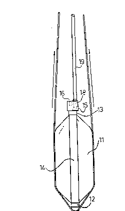
Flg l 6hows ~n anchor whlle drlven lnto the soll
~lg 2 6hows the &~me anchor exp~nded
Flg 3 ~how6 the 6ame nnchor whlle belng dl6~0unted
Flg 4 6hows enl~rged the front end of the ~nchor shown ln Flgs 1-3
Plg 5 ls ~ ectlon along the llne~ 5-5 ln Flg 4

W O 93/01360 PCT/SE92/00508
2 1 1 ~ 7 ~ 1 2
In Flgs 1-3, an expanslble anchor body 11 ls shown.It ls generally of
the klnd descrlbed ln EP-0112316-A and wlll therefore not be descrlbed
ln det~ll but EP-0112316-A ls lncorpor~ted by way of reference. The
~nchor body 11 ls made of two steel sheets that are welded together
~ ong thelr longltudinal edges and folded ln a zig zag form so that they
form a cylindrical pole with rectangular or qu~dr~tlc cross ~ection(F~g
1). A cup 12 covers ~nd ~eals the front end of the pole and an annular
cup 13 surrounds the re~r upper end of the pole. Pour flats 14 are
welded to the cups 12,13. There ls a sealln~ vlscos agentt for example
~sph~lt, in the cups 12,13 ~nd the cup~ are held together by the flnts
14. A solld ~teel block 15 ls welded to the re~r cup 13 and it h~s a
.~ ~ bllnd bore 16 for the-end of a rock drlll exteDsion rod 17 and a bore 18
wlth ~ flttln~ for ~ hose l9. The bore 18 ends ln the center of the
~nnular cup 13, thnt ls, lt ls open to the lnterlor ~pnce of the folded
~teel sheet~. When a pre sure fluld, for ex~mple ce~ent grout, 1~
~upplled under pre6sure through the hose 19, the folded sheet met~l body
lldevelops lnto n clrculnr cyllnder wlth conlcal ends (Plg 2~. Durlng
thls lnflAtion, the fl~ts 14 stlll hold the cup 12,13 ln place.
Flgur 4 show6 the front end of the anchor body 11. A p~rt of a pulley 22
wnth three grooves for three tenslon llnes, for es~mple ~teel ropec or
str~nd6, ls welded to the cup 12. It lt protected by a steel plAte 23
th~t 1~ c~rrled by two rlgld bolts 24,25 that ~re ~l~o welded to the cup
12. A bow-for~ed pl~te 26 ls supported by support pl~tes 27,28 welded to
the pl~tes 23,26. In Plgures 1-3, one of three pnrallel steel ropes 29
can be seen. They are devlated over the bow-formed support 22 (the pnrt
of ~ pulley).
A ~equence for the lnst~llatlon of the anchor wlll now be descrlbed.
The hqse 19 ls coupled to the block 15 nnd the three p~rnllel ~-teel
ropes 29 are lnserted between thelr bow-formed ~upport 22 nnd thelr bow-
for~ed protection pl~te 26. A conventlonal crawler drlll rlg wlth ~ rock
drllllng ~chlne cnn adv~ntageously be used to hamoer down the anchor
body 11 wlth the end of the drlll rod 17 lnserted ln the bllnd bore 16
of the block 15. The rotntlon should of course be off. The nnchor body

W O 93/01360 PCT/SE92/00508
~ 2~12~
pulls the hose 19 and the three steel ropes 29 with lt as it ls forced
down lnto the soll. When the anchor body has reached a competent layer,
the drill rod, whlch ls a conventional extenslon rod, is wlthdrawn and a
conventlonal cement grout pump ls coupled to th~ hose 19 and cement
grout ls lnJected lnto the ancbor body 11 to lnflate lt. The steel ropes
29 are forced outwardly by the anchor body 11 ~nd thelr devlatlon angle
ls reduced. The slx ends of the steel ropes can be coupled and tenslon
loaded almost lm~edlately slnce they wlll only apply compresslve forces
on the anchor body and the cement grout can stand the compresslve forces
almost lmmedlately. The flats 14 wlll be between the ropes 29 and the
anchor body 11 whlch ls advantageous slnce lt will dlstrlbute the load.
It ls ~n advantage that the ropes are not loaded untll thelr angle of
devlatlon has been red~ced due to the lnflntlon of the anchor body 11.
The two ends of each rope should be equally tenslon loaded in order to
~vold sllppage ln the rope support 22 at the front end of the anchor
body 11.
Most anchors are used only temporary and lt ls an advantage that the
6teel ropes can be wlthdrawn when the snchor has been used. As cnn be
seen ln Pl~ure 3, slmply by pulllng one end of the rope the rope can be
wlthdrawn. The rope wlll sllde ln lts support 22.
-
A modlfled steel rope arrangement ls shown ln Flgures 6-8. Pour steel
ropes 29 are coupled to a yoke 40 at the front end of the anchor body
11. By pullln~ only one or two of the ropes, the yoke wlll detach from
the anchor body and the ropes and the yoke can be pulled out of the
soll.

Dessin représentatif
Une figure unique qui représente un dessin illustrant l'invention.
États administratifs

2024-08-01 : Dans le cadre de la transition vers les Brevets de nouvelle génération (BNG), la base de données sur les brevets canadiens (BDBC) contient désormais un Historique d'événement plus détaillé, qui reproduit le Journal des événements de notre nouvelle solution interne.

Veuillez noter que les événements débutant par « Inactive : » se réfèrent à des événements qui ne sont plus utilisés dans notre nouvelle solution interne.

Pour une meilleure compréhension de l'état de la demande ou brevet qui figure sur cette page, la rubrique Mise en garde , et les descriptions de Brevet , Historique d'événement , Taxes périodiques et Historique des paiements devraient être consultées.

Historique d'événement

Description Date
Inactive : CIB de MCD 2006-03-11
Demande non rétablie avant l'échéance 2002-07-02
Le délai pour l'annulation est expiré 2002-07-02
Réputée abandonnée - omission de répondre à un avis sur les taxes pour le maintien en état 2001-07-03
Lettre envoyée 2000-08-02
Exigences de rétablissement - réputé conforme pour tous les motifs d'abandon 2000-07-20
Réputée abandonnée - omission de répondre à un avis sur les taxes pour le maintien en état 2000-07-04
Modification reçue - modification volontaire 1999-11-12
Lettre envoyée 1999-06-21
Inactive : Renseign. sur l'état - Complets dès date d'ent. journ. 1999-06-21
Inactive : Dem. traitée sur TS dès date d'ent. journal 1999-06-21
Toutes les exigences pour l'examen - jugée conforme 1999-05-31
Exigences pour une requête d'examen - jugée conforme 1999-05-31
Demande publiée (accessible au public) 1993-01-21

Historique d'abandonnement

Date d'abandonnement Raison Date de rétablissement
2001-07-03
2000-07-04

Taxes périodiques

Le dernier paiement a été reçu le 2000-07-20

Avis : Si le paiement en totalité n'a pas été reçu au plus tard à la date indiquée, une taxe supplémentaire peut être imposée, soit une des taxes suivantes :

  • taxe de rétablissement ;
  • taxe pour paiement en souffrance ; ou
  • taxe additionnelle pour le renversement d'une péremption réputée.

Les taxes sur les brevets sont ajustées au 1er janvier de chaque année. Les montants ci-dessus sont les montants actuels s'ils sont reçus au plus tard le 31 décembre de l'année en cours.
Veuillez vous référer à la page web des taxes sur les brevets de l'OPIC pour voir tous les montants actuels des taxes.

Historique des taxes

Type de taxes Anniversaire Échéance Date payée
TM (demande, 5e anniv.) - petite 05 1997-07-02 1997-06-25
TM (demande, 6e anniv.) - petite 06 1998-07-02 1998-06-05
Requête d'examen - petite 1999-05-31
TM (demande, 7e anniv.) - petite 07 1999-07-02 1999-06-25
Rétablissement 2000-07-20
TM (demande, 8e anniv.) - petite 08 2000-07-04 2000-07-20
Titulaires au dossier

Les titulaires actuels et antérieures au dossier sont affichés en ordre alphabétique.

Titulaires actuels au dossier
SOILEX AB
Titulaires antérieures au dossier
BO TORBJORN SKOGBERG
Les propriétaires antérieurs qui ne figurent pas dans la liste des « Propriétaires au dossier » apparaîtront dans d'autres documents au dossier.
Documents

Pour visionner les fichiers sélectionnés, entrer le code reCAPTCHA :


Pour visualiser une image, cliquer sur un lien dans la colonne description du document (Temporairement non-disponible). Pour télécharger l'image (les images), cliquer l'une ou plusieurs cases à cocher dans la première colonne et ensuite cliquer sur le bouton "Télécharger sélection en format PDF (archive Zip)" ou le bouton "Télécharger sélection (en un fichier PDF fusionné)".

Liste des documents de brevet publiés et non publiés sur la BDBC .

Si vous avez des difficultés à accéder au contenu, veuillez communiquer avec le Centre de services à la clientèle au 1-866-997-1936, ou envoyer un courriel au Centre de service à la clientèle de l'OPIC.

({010=Tous les documents, 020=Au moment du dépôt, 030=Au moment de la mise à la disponibilité du public, 040=À la délivrance, 050=Examen, 060=Correspondance reçue, 070=Divers, 080=Correspondance envoyée, 090=Paiement})


Description du
Document 
Date
(aaaa-mm-jj) 
Nombre de pages   Taille de l'image (Ko) 
Abrégé 1995-08-18 1 45
Revendications 1995-08-18 2 62
Dessins 1995-08-18 3 78
Description 1995-08-18 3 134
Description 1999-11-11 7 349
Revendications 1999-11-11 14 620
Dessin représentatif 1998-12-16 1 6
Rappel - requête d'examen 1999-03-01 1 117
Accusé de réception de la requête d'examen 1999-06-20 1 179
Courtoisie - Lettre d'abandon (taxe de maintien en état) 2000-07-31 1 184
Avis de retablissement 2000-08-01 1 171
Courtoisie - Lettre d'abandon (taxe de maintien en état) 2001-07-30 1 182
Taxes 1999-06-24 1 47
PCT 1993-12-30 11 408
Taxes 1997-06-24 1 52
Taxes 1998-06-04 1 66
Taxes 1996-06-06 1 56
Taxes 1995-05-11 1 51
Taxes 1994-06-26 1 44