Note: Descriptions are shown in the official language in which they were submitted.
W(~ 93/237XX PC~/C1~93/009X9
21~2!~69
Dîsplay Devices
This invention relates to display devices, andparticularly to ferroelectric liquid crystal display devices.
The majority of liquid crystal displays ~LCDs) rely on the
use of two polarisers to renGt.~ visible the difference between the
switched and unswitched regions~ These polarisers are disposed one
each side of the LC cell. The appearance of the display depends
critically on both the performance and the alignment of these
polarisers.:
: For example, in a:twisted nematic LCDg one polariser is
aligned so that~lts~absorpt1on axis is either parallel or
perpendicular to ~the~alignment directio:l of the liquid crystal
molecules (the director~ on the neighbouring wall: o~ :tle cell . The
other polariser~i~s~arranged either parallel ~or a dark OFf state)
or perpendicular (for ~ bright OFF state) to the first polariser,
and 1S placed on the second wall of the cell~ Such arrangements are-
well known in the art.
n ferroelectric LCDs, which operate by switching the LC
director in the plane~of the LC layer, ~he polarisers are generally
set to be crossed, with one polariser axis pardllel to the LC
director in one of the display states. Such polariser alignments
provide displays with high contrast which are suitable ~or viewing
in transmission and are well knswn to those skilled in the art.
Reflective LCDs are constructed in the same way, but with
an additional re~lective layer (generally non-specular) disposed
WO ~3/2378X PC~/GB93/OOg~l)
.,969
behind the rear polariser. Therefore light passes through the
polariser/LC cell/polariser combination twice in opposite
directions. It is found that displays constructed using
conventional methods described above are very dull and difficul~ ta
read. They maintain high contrdstJ ~ut, because of the double
passage of the light through the display, the nominally "bright"
states are, in fact, also rather dark, making them difficult to use.
It is an object o~ the present invention to provide an
improved reflective ferroelectric liquid crystal display.
According to the invention there is provided a reflective
liquid crystal display device, comprising a ferroelectric liquid
crystal cell; a first polariser through which light from a light
source passes before passing through the cell; a second polariser
through which the light passes after passing through the cell; and
means to reflect the light back through the second polariser, the
cell and the first polariser in that order for viewing by an
observer; wherein the first and second polarisers are orientated
with their directions of polarisation at angles of ~ and ~ ,
respectively~ rela~ive to an alignment direction, the value of
O~ ~ being de:termined from the formula
1 -sec(40~) + ~se~(4~ 8
~ + ~ = 0-5 cos
where the optic axes in the two switching states of the liquid
crystal material are at angles f ~c and ~~c~ respectively, to the
alignment direction.~
An~embodiment of the invention will now be described, by
way of example, with reference to the accompanying drawing, in which
Figure 1 is a schematic sectional view of a reflective
ferroelectric liquid crystal display device, and
Figure 2 illustrates9 schematically, angles relevant to
the present inventionO
:`
WO ~3/237XX ~ 3 9 PCT/GB93/009X')
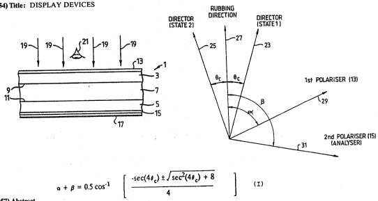
Referring to Figure 1, a reflective liquid crystal display
device 1 comprises substrates 3 and 5 which contain therebetween a
layer 7 of a ferroelectric liquid crystal material. The inner
surfaces 9,11, respectively, of the substrates 3 and 5 are rubbed in
a predetermined alignment direction, the direction being the same
for both substrates. A first po1ariser 13 is located at the upper
surface of the substrate 3 and a second polariser ~analyser) 15 is
located at the lower surface of the substrate 5~ as viewed in Figure
1. A reflective layer 17 is disposed beneath the polariser 15~
In use of the device 1, light, as indicated by arrows 19,
passes through the polariser 13, the substrate 3, the liquid crystal
layer 7, the substrate 5 and the polariser 15, and is reflected by
the layer ~7 so ~hat it returns through those elements to reach an
observer 21. The liquid crystal material is switched between bright
and dark states by application of an electric field thereto, using
suitable electrodes (not shown) provided on the substrates.
Known displays of this kind are generally adjusted for
high contrast ratio. The contrast ratio, R, is the ratio of the
transmission of the bright state, T1, to that o~ the dark state, T2.
These transmissions may be taken at a single wavelength, e.g. 550nm~ ;
to match the peak of the human eye response curve, or are pre~erably
taken as an integral oYer the range of wavelengths to which the eye
is sensitive. It is common to derive the luminance transmission Y
of an LCD as
~7~ :
Y = kJ T(~)S(~)Y(~)d
3Sl;o ~ ' !
where Tp) is the transmission spectrum,
- S ~ is the spectral intensity distribution of the light
source used for viewing the display,
' :
y p) is the 1931 CIE colour ~atching function which
equates with the eye response function,
w O 93/2378X P ~ /cBs~/nosx~
~ 969 -4- . :
and k is a normalising factor given by
710
k = 100 ~J S ~y ~ d~
3~
The ratio of the luminance transmission of ~he bright
state, Y1, to that in the dark state, Y2~ is the luminance ~ontrast
ratio. It is this which is usually optimised.
In a simple conceptual ferroelectric liquid crystal
display the device acts as a ~-wavelength plate at 550nm, the optic
axis of the device being switched thr w gh 4~, i.e. twice the
smectic C cone angle ~c of 22.5. The device is placed between ~.
crossed polarisers with the optic dXiS in one state aligned with a
polariser. This provides the ideal device, and this condition can
be approached by hard-driven shutter cells. Multiplexed FLCDs, on
the other hand, do not switch through 45. Indeed, in many cases,
switching angles as low ~s 15 are encountered, i.e. an effective
cone angle ~c of approximately 8. ~f su~h a cell is placed between
crossed polarisers as above, then the bright state reflectivity will
be only about 1.2X using polarisers obtainable in practice ~i.e. no~
theoretic~lly ideal polarisers). Such a device produces a Yery dark
and barely acceptable display.
Howèver, in accordance with the present invention
diffe~ent configurdtion is used. Referring to Figure 2 of the
drawings, the directors of the ferroelectric liquid crystal material
in its two swi:tching states are orientated at angles ~ ~c and ~c to
the rubbing (alignment) direction 27~ as indicated by lines 23 and
25, respectively. The fi~rst polariser 13 is orientated so that!its
optic axis is at an angle o~ to the rubbing direction~ as indicated
by a line 29, and:the second polariser 15 is orientated so that its
optic axis is at an angle ~to the rubbing direction, as indicated
by a line 31.
The values of the angles are determined in accordance with
the following formula
WO ~3/2378~ 21 12 9 6 9 P~/GB93/009~
-5-
+ ~ - OS cos-l [ seC(q~c~ ~ ]
Assuming a cone angle ~c of 8 as mentioned abovel ~+ ~ is
31, and the bright-state reflectivity is 17.8%, which gives a
bright legible image.
For a different embodiment of the device, the cone angle
~c might be 15. Using the orientations determined in accordance :
with the invention, a bright-state reflectivity of 20.25% is
obtainable, which is within 0~25% of the maximum achievable. This
gives a very bright display. Using the conventional orientations9 a ~:
bright-state reflectivity of only 11.5% would be obtainable.
Instead of the ~erroelectric liquid crystal material
mentioned above, a ferroelectric liquid erystal polymer might be
used. In that case, the alignment direction would s~ be the
direction in:which a nematic liquid crystal material would align ~:
gi ven the~ same al i gn-ent surfaces .
.
,
: : :