Note: Descriptions are shown in the official language in which they were submitted.
- W093/03256 PC~/AU92/003~i9
~ 21iL3~7~
A CABLE BOLT
FIELD OF INVENTION
The present invention relates to the field of bolts, bars and wires and similar
devices used for example, as ground or rock suppon and reinforcement in geological
5 environments ineludin~ underground mines or tunnels or other stabilisation applications
and also more generally to reinforcing applieatbns. The present invention also relates to
end fittings or means for seeuring the bolts, bars or wires.
Numerous examples exist of types of roek or ground stabilisation bolts having the
1 0 form of a ri~id bar. The rbid bar generally has an elongated shank for insenion il~ a
borehole drllled from an~ excavation into surrounding roek, which is to be eontained or
stabilised. The instal~ed bar acts as a rock bolt, which together with a plate and nut
provided at one end of ~he bar seNe to reduce the risk of collapse of the rock forming the
~roof or walls or uplift of the~floor of the excava~ion.
1 5~ ~ The borehole is usua'ly drilled to 8 depth so that one end of the rigid bar and at
least a; portion of the length of the bar aqacent to thls one end is secured to relativety
stabl~ rock by a fast~ setting~ resin mix, other grout formulation or mechanical anchor
~Sueh~ rbid bars = ohen ~ limite t use where a borehole must be drilled deep into
`~ 20 ~the roof~of ~he excavatbn before relativety stable strata is loca~ed or where thicker zones
a~è~to~be reinforeed. The rigid~ bars~ are relatively inflexible, and thus a bar of greater
I ength~ ~han ~he heigh~ of the mine or ~unnel or any o~her type of exeava~ion without being
plàs~ieally ~deformed ~and then`straigh~ened again before~ing inserted in~o the borehole.
o~ Rbid bars~ofaparthular ~diameletalsohavearelatiwly limited-loadearrying eapaeity
25~ ~and~th~refore a relathe~y large~;number o~ dgid bars~ must be used over any gwen area ~o
aehieve; the ~ required~ support or reinforeing ae~bn. ~
A eable form of ~ rock bolt is shown in Gerrna n Paten~ Applieation DE34351 17A.The eable form of rock bolt diselosed ~herein has a rigid end or sbeve portion lormed a~
he end of the eable parl of ~he ~bolt to enable a pla~e and nu~ ~o be fmed ~o the bolt. The
;~30 rigid end is usually preforrned on the eabb by ~easting or swaging for example, and
therefore the cable boll is provided in a predetermined length. Accordingly, a cable bolt
must be ordered and~ provided to Ihe excava~ion site, depending on the borehole depth.
This is often not practieal, where the depth of boreholes needs to be varied from area to
~-~ area.
~,,
:
:~
WO 93/03256 PCI/AU92~00369
211307~ 2
Another cabl~ form of rock bolt is discJosed in U.K. Paten1 Specification No.
GB2084630A. The cabl9 disclosed therein has an anchored swivel at one end of the cable
which is inserted into the borehole in order to s~cure the bol~. At the other end of the
bolt there is provided a portion of rigid bar onto which a plate and nut can be fitted. In
5 manufacturing the rock bolt G~2084630A difficulty is encountered in attachin~ a rigid
bar to the cable and also relatively higher costs are involv~d in its manufacture.
Problems similar to that of DE34351 17A with regard to varying borehole depth equally
apply in resp~ct of the bolt dîsclosed in GB2084630A.
A further problem encountered with rigid bar bolts as noted above is their limited
10 bad carrying capaGity per unit bolt diameter. When the rigid bar bolt is in situ, the Idad
of the rock forming the immediate roof of the excavation which is to be supported is
transferred to the ri~id bar or known cable form via a plate by means of the threaded
area be~Neen the nut and rigW end of the known bolts.
Devices of this general type which are inserted into driîlholes and bonded to the
15 rock are subject to possible axial ~orces and shear forces, the latter occurring as a result
of at least partial sideways movement of certain rock zones. Thus, to prevent premature
~:
y~elding of the device when ri~id bars are used, there is a tendency to use bars of greater
; ~ diame~er. However, this necessRates use of a heaYier anâ more expensive bar and
requires a larger diameter borehole to be drilled in~o the rock. It would be seen of
2 0 advantage to heep ths diamebr~of the exposed end of the bolt small because small holes are
~more ~subed for maximum driliing speed and to form a small annular zon~ between the
borehob and ihe bolt for efficient resin mixing and maximum bond strength deYelopment.
It would b~ an advantage to provid~ a cable rock bolt which is able to catry larger loads
han ~that of known rbid bats of the same-diameter so that bor~hole diameters and time of
25 drilling~nd installation can~be kept to a minimum. ~ - c~ ~
It has also besn found to be sometimes difficult to agitate resins in the borehole to
ensure correct rnixing of constituents due to the substantially cylindrical nature of some
prior art bars.
~ECTS OF I~TION
-~ 3 0 An object of 1he present invention is to alleviate some of the problems of the prior
art.
A further object of the present invention is to provide a cable bolt for earth or
rock stabilisat~sn whTch is adapted for fitment into a borehole irrespective of its depth.
A further object of ~he present invention is to provide a cable bolt adapted for use
3~ with relatively small diameter holes
W0 93/032S6 P~/AU92/00369
3 ~ . ~
A further object ot the present invention is to provide a cable bolt which is
adapted to carry relatively lar~er loads.
A further obiect of tha present invention is to provide a means of agitating resin
in a borehole in association wi~h a cable bolt.
A Slill further obJect of ~he invzntion is to provide a method of support with the
end of each support formed simply including formation at th~ f~ë on segments of cable
taken from a reel attached to an automatic support placement machine.
SUMMARY OEINYEUTIQ~I
The present invention provides a device adapted for rock or earth stabilisa~ion and
10 reinforcement. The device is provided in the form of a single stranded cable or cable ~olt.
The cable bolt of the present invention is adapted to have a nut fit1ed directly onto one end
of the cable. Nor is there a need to have pre-threaded cables. The present invention
nables fitment of the nut directly onto the cable. The cable may be cut, in siSu, to any
desired iengthl and have a nu~ fitted directly to an end of the cable. In this way, cables or
15 rigid ban of fixed length are therefore no longer required.
Thepresent invention further provides acablebolt which comprises aplurality
of; wires. One end of the cable bolt is adapted to have a thread rolled thereon. A nut placed
on ~he threaded ponion of the cable bolt serves to interen~age the wires of the cable. This
allows bad to be transferred to each wire of the cable. The cabte bolt is therefore adapted
20 to~carry relatively larger loads lhan known bars w3th ri~idly formed ends.
The wires of the cable bolt of the present invantion may be interwound, bunch~d
ot`~othefwise arranged.~ln a preferred form of the present invention, the wires are
pataltel layed althou3h cross ~lay may also be utilked. The oontact areas between wires of
t he boU thus ~extend ahng the surfac~ of each; wire~for. the entire length of the oable. The
2 ;5~ pr~sent invèntion further~ provides a cable bolt, ~formed of a plurality of wires, whlch
has a relat~ely dense construction of wires in strand cross-section. Filler wires may
als~ be provided in bstween outer and inner lays of wires, to provide an even greater area
'
~ for the transfer of load from the nut to the cable wires.
~, I ` . ~
The presen1 invention ~also provides a cable bolt, the outer wires of which are
i 3 0 wound with a lay direction ~opposite to the screw direction of the thread or spin direction
of the cable. The cable bolt of the present invention may advantageously be installed in a
; ~borehole together with a resin/3rout cartridge. The lay direction of the outer wires as
notad abwe provides a number of advantages. One~advantage is that after a nut is threaded
onto one end of the cable bolt, the cable bolt is usually rrade to rotate until the resin in
3 5 ~he borehole around the olher end of the cable bolt sels. The lay direction being provided
WO 93/032~6 PCI/AU92/00369
.
2113~7~ 4
in a direction opposite to the screw direction of the thread, or spin direction of the cable,
serves to cause a pumpin~ action on the resin in the borehol~, and pumps the resin
toward the cbsed end of the borehole. This pumping ac~bn serves to ag;tate and mix the
resin before it sets.
Another advantage provided by the lay directbn of the outer wires is that it serves
to reduce de-laminatbn of the wires of the cable bolt as a result of threading the nut onto
the cable. The lay directbn also serves to bck up the outer wires as they are rotated in
the thread direction during rolling ~ of the thread and enables a consistent thread to be
formed on each ou~er wire;of the strand.
:::10 : ~ The present inventbn provides a cable bolt comprising at least two wires, the bolt
being aoapted to have~a nut threaded directly onto at least one of the wires. The cable bolt
may~ have~the at least two wires: interwound.
The present invenlion ~a'so provides a cable bolt comprising a central wire and an
outer layer formed of aplurality of wires wound aboutsaid central wire, athread form
1 S formèd; directly onto ~he ~wi!res in saW outer layer at one end of the cable bolt, said thread
: form being ad4ted~to have a nut th~eaded lhereon.
ln: one~brm ~lhe :cable~bolt;~may have at bast one interrnediate layer provided
n ~ brtween said~cen~ral wire~and~ said ~ouler layer, the wires in said intermediate layer or
layers~ :and:said ou{er ~layer being~ wound around said cen~ral wire in a predetermined lay
2~0 ~directbn~with 1he wires in~each~àyer being substanlially parallel lo one another.
T~he~thread form ~may~ rolled onto the wires of said outer layer.
b ~ The:~thread formimay~ be~ rolled in a direction opposi!e to lhe lay direction of the
, .Th ;fr e:~en~ of ~the.-wirès ~ated at or~ end of the ~le bolt may be secured to one
2 5 ~a it r,~for: èx~pb, ~ tin~. ~
The~ tormatbn:~: of ~the~thread ~may serve to inlerengage wires forming said cable
The present invention also provides a method of installing a cable bolt in a rock or
eanhen formatbn, said method~oomprising the steps: of:
: 30 forming a borehole~:in~said rock or earthen brmation;
placing a settable~ securing malerial cartridge in said borehole followed by cable
bolt malerial from a storage:facility for said cable bolt malerial;
separating a prèdetermined length of said cable boll material from said storage
faalily and securing ends of wires of the cable boll malerial al a free end of lhe cable bolt
35 malerial;
:~
:
WO 93/03256 P~/AU92/00369
2113Q~
rolling a thraad form on said free end of the cable bolt material;
applying a plate and a retaining nut to the thread form on said cable bolt material;
rolating said cabte bolt material lo activate said secvring material cartridge; and
once said securing ma~erial has set, tightening said nut on said thread form.
The present invention may further provide a cable adapted to use as a cable bolt,
saW cable comprisin3 at least two wires.
The prasent invention still further provides a nut adapted to radially compress
,
wires of a cable bolt.
The nut may have at least one axial slot therein.
1~0 The presen~ invention still further provides in combination, a cable bolt
oomprising at least two wires, an outer surface of the cable bolt having at least one
depression formed therein; and~
an end fining ~ec to co-operate with said depression whereby in use removal
of the end fitting from the cable bolt by axial movement only is substantially prevent~d.
1 5~ The depresshn may~ formed ~by a groove in one of the wires.
- The~present inven~ion also provides a method of proYiding an end fitting on a eable
boU, saiid~method comprisin~ the steps of:
a) ~ providin~ at leas~ one depression proximate~ an end of said cable bolt, said
depression keing adapted to co-operale with said end-fltting; and
20~b~ ins~allin~ said end fit~ing directly onto said~cable bslt in a manner in which the
end-fiuing is~substan~ially~ held in place on said cable bolt.
A~preferred ~embodiment of the ~present inverilion will now be described with
refereno0~ to 1h~aocompanyjng drawings, ~ wherein lilu~ n umerals are used to refer to the
~me~ ~m~ent ~,~and ~w erein ~ F`~
2~5 ~ Fi~ure~ shows~ a cable bolt of 1he presenl inven~ion installed In a boretlole.
19 ~ Figure 1A shows~an altemative form of retaininQ nut;
Fbure 2 shows~in~ cross-section, a preferred~ form of cable bolt in acoor~ance
with the presenl invention.
Figure 3 shows in~ se~tion, the threaded end of a cable bolt in acoordance with the
3 0 present invention, with a nut in place,
Figure 4 shows a preferred method of manufa~turing and installing a cable bolt in
accordance wdh the present invention.
Figure 5 shows one forrn of one nut.
Figures 6 and 7 show examples of collars and plates.
3 5 Figure 8 shows one form of conventional nut.
WO 93/Q3256 PCI`/AU92/00369
Z113~7~ 6
Figure 9 shows diagrammatically ~he present cable bolt used as an earthen or rock
stabiliser.
Figure 10 shows diagrammatically the present cable bolt when subject to lateral
movem6nt;
Fi~ur0 11 shows graphically a representative comparison of holding between the
present cabte bolt and prbr art rigid bar; and
Fi~ure 1~ is a ~able showin~ preferred strand cross-sections and diameter rangesfor the cable bolt. ~ -
::
1 ~ The present invention provides a cable bolt, which has numerous applications, for
10 example in building or civil construction, rock and earth stabilisation and~or
reinforcement, or any other application which currently involve the use of cables or
rods as fixing elements or as reinforcement.
~ ~ A preferred embodimen~ of the present invention wiil be described with regard to
; an applieation in earth or rock stabilisation. The present invention should, however, not
` ~ 1 5 ~ be seen as~being limited to such ~an applbation. For example, the cable bolt may be used
in a supportin~ function, Figur~ 9, i n which lhe cable bolt 6 may be substantially fully
encapsulated~ by reslns ~in a bor~ ho~e 4. In 1his way, the bolt may act to reinforce an
unstab!e~ portion of earth 2 ~and enhance its strength properties so it becomes selS
supporting.
2~0 ~ Fu~rthermore, ~ althou~h the present invention is discbsed in the embodiment with
only~ one~threaded~end, it is to bs under~tood that applicatbns exls! wher~ both ends of the
cable bolt can be threaded in a~ similar fashion ~o the one end desoribed, to receive a nut.
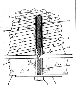
u~Thus, with referencé to an~application of the~present invention in the field of
~ earth;~or rsck stabillsation, ~ and in particular a mining or tunnel excavation,~Figure 1
;~ 2 5~ shows~a~roof sectbn 1~ ot ~a tunnel.- The rock above and forming the tunnel roof 1
comprises,~ for examp!e, a ~elatively unstable portbn 2,~and a relativ~1y stable portion
3.
In such situations a cable bolt according to thB present invention is installed, to
r educe the risk of the unstable portion of the tunnel collapsing.
A borehoie 4 is drilied into the tunnel roof, or wherever the earth or rock
requires s~abilisation, to a depth which enables one er~ of the cable bolt to preferably be
fixed to the more stable portion 3. Each borehole depth may vary from hole lo hole,
dep~nding upon th~ location~ of a sUitablB portion.
Grout 5 is inserted in the borehole 4, in a manner known to the skilled person,
3 5 and the cabie ~olt 6 of ~he present invention, shown of length greater than the length of
'
::
WO 93/03256 PC~/AU92/0036g
~1~ 3~7~
7 - - ~
the borehole to enable a nut and plate to be fined on the exposed end, is thereafter
insened into the borehole. There are si~uations where grout 5 would be inserted alter
the cable bolt 6.
A threaded portion may be formed prior to or subsequent to installing the cable
5 bolt. It is usual practice however, in the art to forrn the thread prior to installation of
the eabb bolt. The threaded por~ion is preferably formed by rollfng. Il is believed that
thread cufflng wouW remove metal from the outer wires of the cable and reduoe the load
carrying capacity of the cable bolt whereas rslling deforms the metal and creates a raised
~be whieh protrudes slightly above the preformed surface of the outer wires. The; 1 0 deformation is also believed to ~ work harden the outer wires thereby increasin~ their
strength which partly compensates for the reduced cross section area caused by thread
forming. ~ ~ ~
In installation, a plate 7 is plaoed on the cable bolt 6, and then a nut 8 is threaded
onto the cabb bolt to ho'd ~he p'ate 7 against the tunnel roof 1.
As described above,~ the plate 7 serves to hold the unstable portion 2 in place by
edudng~ its ability to ~break away from the stable porlion 3. The purpose of the plate,
shouW~be to transfer any surface rock movement into streteh in the cable which tesults
in a ~resistance force~ ~being~ generated in the` eable whkh acts on the plate and whieh
resists ~further ~movement o f the- surfaee.~ `More details of the load transfer will be
20 hereinafter~described~ with reference to Figure 3.
Fbure~Z~shows~one~form of cable bolt in acoordance with the present invention.
` The eable bolt has one~kin~ or central wire 9, an inner layet of live wires 10, an outer
layer of ten~wires 11, and filler wires 12~pl~aced betweenithe outer and inner layers.
lt is ~important to;~note tha~ ~Figute 2 shows only one~exemplary form of the
2~5~ presént ~invention. The~present~invention may; comprise~ any number of wites, strands,
ropès and cables, dependbg upon the a~plicaticn.
I t is to be noted ~hat, in cabb cross section larger bad carrying capacity may be
~, provided by forming the cable of a re!atively large number of wires, each wire having
; ~ reiatively high streng~h. The use of a plurality of wires enables each wire to carry a
30 portion~o f the load. ~ ~
Strand geometry can be~selected according to the following criteria:
- outer wire diameter~needs to be sufficisntly large so that thread or groove
indentations do not exceed 20% of outer wire diameter and to provide sufficient
.
:
~:
W0 93/03256 PCI`/AU92/00369
211307~ 8
flexural rigidity for the strand; experience has indicated that outer wires in the
diamster range 5.0 to 5.5 mm are preferred;
~iven the above requirement for outer wire size, the numb~r of outer wires
depends on the strand diameter required; and
5 core wires, if appropriate, and the central wire of the strand must pr~ferably
have a diameter ~hat will allow lhem to be forrned into a Ucios~ packed" struc~ure
(i.e. each core wire has as many contacts as possible with other c~re wires, thecentral wire and the outer wires). Note that to achieve a close paoked stnJc~ure, a
parallel lay s1rand construction is required. However, it is also possible to have
1 0 a cross-lay construction in which the outer wires are wound with a lay direc~ion
opposite to the core wires, as herein disclosed.
Examples (only) of preferred strand cross-sections and diameter ranges are
shown in Figure 12. These are typkal examples of size ranges that would be suitable for
the cable bolt when it is used for fully bor~ed rock support / reinforcement installed
1 5 wlth resin cartridges. Many other ~pes and/or forms of cable bolt are contemplated i n
accordance with the applicalion to which the bolt is to be subjected. The present
description Es to b~ used by an artisan as a guide to the canstruction / canfiguration of
olher~*pes and/or farms of cable bolt.
Referring to Figure 2, one form of cable bolt as described a~ove, has application
2~0~ in the mining field.~ ~
T he dimensions and make up of the particular strand cable that may be used are as
folbws: a ~central king wire~is 3.80 mm in diameter, king wire is surrounded by five
5) ~wires ~ e~ch 4.53~ mm in diameter, five (5) filler wires of diametar 2.1 mm are used
in~the outerglooves behlieen the 4.5~mm diameter wires, andten ~10~ wires 4.9 mm5~-2~5 in~diamet~r are wound around the outsid~
The outer diame~er is approximately 23.1mm.
Noting the above,~1rials of the cable of~one form of cable bolt have shown: the
outer wire diameter should be as large as possible compatible with the outer strand
diameter required and llexibilny (i.e. bending stiffness). For a strand with diameters in
30 therange 22.8 - 23.3 mm, a design withten (10) outer wireshasbeen foundto allow a
iow enough bending stiffness for mining ground suppor~ applications. STmilarly, a strand
with adiam~ter range from 15.2 ~o 16.0 mm with six ~6) outer wires is still flexible
- ~ enou~h for the above purpose. With both these size ranges, the outer wire diameter is
~ ~ ; preferably in the range 5.0 to 5.5 mm.
~'
- WOg3/03256 PCI`/AU92/00369
; 2113~7~
~. .
Al~ wires in the strand except the centrs (or kin~) wire should be wound in
parallel lay with a lay direction opposite to 1he screw direction of 1he thread.The cross s~ctional area within the core of the strand (i.e. the area bounded by the
total number of outer wires arranged in their radial position) is to be as tightly packed
5 with wires as posstble. This is required to maximise the numbqr of radial cosltacts for
each wire in the corc and to maximise the radial compressive stiffness of 1he core. The
breakin~ str~ngih of the cable is partly dependent on the ultimate strength capacity of the
wires selected for 1he cor~. ~
The above are considered to be impor~ant where the thread is rolled on the outer10 wires. A roll~d thread is preferred unless the outer wires are sufficiently large enough
to enable thread cutting, as it is usually not possible to achiev~ adequate thread depth for
bad transbr purposes withoui excessively weakening ~he outer wires if the thread form
~; is cut into th~ wires. In other words, there may be an optimum condition of thread depth
and outer wire diameter at which the outer wire strength is equal to the failure strength
15 o f the thread when a nut of a specific length is used.
An indentation in an outer wire may otharwise be provided, the indentalion co-
op~rating with a suitable end ~nting. For example, the end fitting may simply be clipped
onto ~th~end ot the cable bolt, whcre a protrusion of th~ end fitting co-operates with the
cable indentation. ~ ~
20 ~ It~is preferr~d that the core is densely packed with wires. The cable bolt of the
prescribed~invention in conjunction with a cone nut or tight fitting conventional nut
utilises th~ phenomena of the nut compressing the outer wires onto the inner core wires
which~may~ In -~urn~ bè compressed onto the~ kin~ wire to develop~sùfficient friction
n 1hé wires, so that, for~example, as the outer wires strQtch ~ under!load, the inner
2 5 ~wires also ~stretGh and~ bui!t up tensile-loa~. - If ~his does not occur, the t~nsile strength of
the cable bolt is only~ lhat of the outer wires, and reduced load carrying capacity results.
For increased load~ capacity of lhe threaded csble it is preferred that the cable be
formed by winding the wires around the cenlral king-wire without using lubricants of
- any kind (rope manufacturers often use grease during the manufacturing process for
30 corrosion protection during the life of lhe produot). Where lubricants are used,
premature slippage may result between inner and outsr wires.
When acone nu~ is used, it is preferable lhat the outer wire diameter is selected
to allow a small space bstween each outer wire. This allows th~ nut to squeeze the outer
- ~ wires on~o Ihe inner core wires more effectively and assist in the load transfer to the
36 inner core wires. This is not always lhe case with a parallel (conventional) nut. The
'
WO 93/032S6 PCI`/AU92/00369
Xil3U ~9 10
squeezing actbn is considered not to be essential to the working of 1he present invention
where there are smaU spaces between each outer wire, these gaps also allow the ~rout or
~lue used to bond the strand to the rock (portion 3 of Fbure 1) in a borehole to penetrats
the voids between outer and inner core wires thereby increasing 1he bond strength.
Where the bad capadly of the threaded strand/cone nu1 assembly is to be cbse to
the maximum andlor at bast 80% of ~the nominal breaking strength of the strand, none of
the wires used to construc1 the strand should be ooated with anti-corrosive layer (such
` ~ as galvanising). These coatings tend to reduce the radial stiffness of the strand and serve
to provide a ~ lubricating effect on~ the wire surfaces when in contact with each other. Both
1 0 these aspects tend to detract from the fric~ional load 1ransfer between the ou1er and core
wires. Coatings which may significan1~y~increase fric1ion may be an advantage.
Figure 3 shows, in cross~ section, 1he interaction of wires of the cable bolt of 1he
present inven1ion. It is~10;be noted Ihat, al1hough central, inner and outer wires are
shown of equal cross-sectiona! area, the wires of 1he;cable bolt may be of any varying
15 cross-sectional area in order to achieve a desired strength capacity.
The central (king) :~wir~e is shown ~as being strabht.
Arolled thread 13~ is~provided onthe outer layer of wires 11. The rollin~ of thehn~ad~has~the added effea of engaging the wires of one layer to the wires of another layer.
Deformations 14 may~be formed where ~the wires are compressed together, in the case
2 0~ whére~a~cone nut is used. ~
Interengaging of these deformed areas serves to improve load carrying ability ofthe~càUe. ~These contact areas 14 serve to transfer or distribute the load applied to nut 8
to tf~e wires of the cabte~ tiott, and~ ~herefore increase the load capacity ot the cable bolt.
ln a~itbn to the interen~a~ement of the wires noted above, a compression nut
Z5~ (for example`the nut shown in Figures 1A or 5) or- a nut~which provides an interference
fit~wah the cable bolt,~may serve to~provide compressive forces radially on the wires.
The~sbts~formed in the nul may be confbured to~allow compression of cable wires asthe
nut is tightened. The sbts may be oriented axially andior radially. Also, the cone section
may be separate to the nut and be engaged by the nut to rotate both cone and nut. The slots
3 0 may also allow be conf'gured to allow for nlovement of the plate and collar in an axial
direction. ~ ~
As shown in section A-A, where the wires are deformed at their interengaged
surfaces during rolling the ~wires increase the area and extent o~ their contact. Where the
wires~ are not deformed, they preferably are arranged to engage each other. Thus wire 11
:: .
~::
WO g3/03256 P~/AU92/00369
211307~
- . 11 ~` ` ' ' '
engages inner wire 10 at 14a and also engages filler wire 12 which in tum engages inner
wir~ 10 at 14b.
Inner wire 10, likewise deforms and interengages its neig~,bourin~, wires, and i n
particular king wire 9 at 14c. As is shown, each, wire of the cable, in this example. is
5 slightly and locally deformed by the thread rolling process to increase contact area
between itse,lf and Us neighbauring wires. This serves to assist in distributing the bad
from the nut, to each wire of the cable bolt.
The nut 8 desian depends on the load capacity desired. Preferably, the thrsad
matches the form o~ the rolled thread on the outer wires. As shown in Figures 1, 3 and 8,
10 the nut may be of conventional shape and length if adequate load transference can be
achieved thereby. For example, ~he nut as shown in Figure 8 in conjunction with a 23.1
mm diameter cable bolt~ has been tested to transfer capacity as follows :-
Nul lenath ~mm)
2 6 3 6
3 o 4 2
3 5 ~ 4 B
;~ The nut can transfer a minimum force equivalent to the s~rength of ~he outer
wires. If 1here is some wire interaction, for example by friction or wire compression,
2 0 the ~1ransfer force can be increased. If improved bad', transference is needeo" thB nut as,shown in Figures 1A and 5~with a frusto-conical end piece 20 might be used. Theer~
s~ctioa 20 has comeniently two sets of diametrically op~#ed axial slots 21 to allow ~he
i ~ r~hns of the~end section 20 to be compressed against ths cable as the nut is
thrèa~, thereon and~ls screwed into a complementary tapered openin~ 11 in the collar
2~5~ ~pieoe used, in association~wi~h a plate. Particulàr~ collar and plate embodiments are shswn
In~Figures 6 and 7. ~A 7 taper on the cone used, in conjunction with a collar with a 7
t apered hoie wnh 3 mm wide slots in the oone allows the opposed regions of the end
section 20 to provide adequate compression when ~he nut in Figure 5 is used in
conjunction with a 23.1 mm diameter cable bolt. The collar in Figure 6 has a spherical
3 C suAace machined on pan of its outer surface to locate and bear on a deformed plate as
~ :
shown. An advantage of this arrangement is that it allows for some plale misalignmen1
fr~m a plane which is perpendicular to the axis of the bolt. In situations where bolts are
installec, perpendicular to the rock or earth surface, a cylindrical shaped collar in Figure
7 can c,e used in conjunction with a flat plate. Collars of the type shown in Figures 6 and
: ::
:
WO ~!3/û3256 PCI/AU92/00369
2113079 12
7 manufactursd from mediurn strength steel provide sufficient confinement of the nut in
Fi3urs 5 if the collar outside diamster is at least 50 mm and the leng1h is at least 22 mm.
Furthcrmore, the rolling of the thrQad is preferred as this deforms the metal ofthe wires so there is a reduction in cross section area of the outer wires of the cable bolt,
5 but this is compensated to a de~ree by the extra str~ngth in lhe wires due to work
hardening proximate the threaded area. Formin~ the thread in this way obviates the need
to use a ri~id bar and alleviates a prior art problem where there may be premature yield
of a rigid bar subjected to shear deformation.
Figure 10 illustrates the typical profile that a rock bolt is subjected to after10 shear movement in the rock has occurred. A rigid bar bolt of the prior art has been fouhd
to be forced to yield and fail after a relatively small shear movement, whereas in the
cable bol! of the presenl invention localised movement between individual wires occurs to
allow relatively high shear movement before wire failure occurs.
Tests of the present cable bolt have also shown that if the end of the cable bolt
1 5 movcs or is pulled out of ~a~ stable zone, an increase in the holding force of the cable bolt in
t~e borehole develops. ~ rigid bar has been found to merely slip out of lhe borehole in
this si1uation. Figure 11 diagrammatically illustrates a comparison between the present
cable boU and a rigid bat in such a situatbn.
With reference to Figure 4, a preferred method of utilising the cable bolt of the
1~ ~ 2 0 present ~inYention is described.
The steps are as follows in this preferred examplel however, the following stepsare not applicable in all installations of the cable bolt in accordanc~ with the present
inventbn ~
(a~ Forming a borehole into~ the excavation rock which is to be stabilised by a cable
;~ ~ 25 - ~ ~ bolt i~i accordanco with the invention; ~
( b ) Cutting a length of cable (V) ~rom a drum of cable enher after feeding cable from
the drum into the borehole or prior to inserlion of the cable into the borehole. In
either method the l~ngth is cut to sui~ the depth of the hole of step (a) above.( c ) At least the end of the cable on to which the thread is to be rolled is welded (W) to
3 0 hoW the ends ot the wires together ~hereby reducing the likelihood of delamination
of the wires ot the cable. If desired, some other mechanical or other known
method could be used to secure these wire ends together.
( d ) Rolling a desired thread form onlo the end ot the cable length secured together by
,
welding or by some other mesns such lhat the outer wires of said cab1e beoome
!f~
WO 93/03256 PCI /AU92/00369
2113~7~
1 3
locally delaminated in the area of the thread rolling where the outer diameter of
the cabl~ increases slightly from the welded or othenHise secured end
( ~) Placing a stabilisation plate with an openin~ ther~in over the projecting end of the
cabie length in the borohole.
6 ( f ) Thr~adin~ a nut onto lhe projecting end of 1he cable length ,until such stage as th~
nut stiffens on the thread as a result of the expanded cable diam~ter or until 1he
end of th~ cable contacts the pin placed aeross the threaded portion of the nut as
shown in Fi~ur0s 5 and 8.
(9 ) Installing thc cable length into the borehole in 1he rock face if this has not already
occurred. Generally, the cable is installed with a plate and nut already fitted. l'he
nut is used to spin the bolt during installation.
( h ) Rotatin~ the nut and cable together so as to break a fast set~ing resin cartridge pre
placed in the borehole and to thoroughly mix the resin ma~erials to secure the
inner end of the cable to the adjacent rock wall within the borehole. The
~; 15 arrangement of the wound wires of the cable having a lay d rection opposi1e to the
thread rolled thereon, when rotated in the direction of 1he thread, provides a
pumpin~ action to the resin materials so that they tend to move inwardly within
he borehole rather than outwardly therefrom while the resin remains liquid.
When the resin has set, the nut is then forced onto the thread of the cable end to
2 0 ~ fail the pin and to press ~the~ stabilisation plate firmly against the rock face.
Alternatively, it is envisaged that the outer wires oan be welded toge~her and
théreafter a thread rolled on either side of the weld. The cable may be then cut ~hrough
ths weWed section.
ln ano~her a51erna~ive, the cable (or a portion thereofl may be thr~ad rolled
2 5 ~irst, after which the cable ~may be cut t~ ~ desired len~th~
In order to successfully install the cable bslt by spinnin3 it through one or mors
resin carlridges, the strand must have sufficient flexural (bending) rigidi~y so that it
does not bend when the thrust is applied to the end of the bolt during installation.- This
30 propeny of ~he strand is primarily a function of the number of outer wires, the outer
wire diameter and the radiai distance of the outer wires from 1he centre wire.
Single strand cable bol~s of the configurations and diameter shown above have
sufficient fl0xural rigidity~ to be installed by the method indicated in the specification.
WO 93/032S6 PCI~/AU92/00369
~13~7~ 14
nLrrER ~RE INDENTATIONS
Althou~h the specif~catbn as it now stands covers indentation of part of each outer
- wire so that a thread is formed, rolled or cut around the strand, the indentations need not
necessarily be arranged to form a thread. The combination of successive indentations
5 around the outer wires to form a thread allows a threaded nut to bs used as the ~end
fitting" to b~ar against a collar and/or plate.
Indentin~ the ou~er wires in this way is only one particular form of deforming the
outer wires. Provided other types of end flnin9 could be used, Ihe outer wires could be
rolled with a set of parallel grooves normal to the strand axis (centre wire). Groove
1 0 dimensions in each outer wire would be the same as for the case when a thread is forrried
- on the outer wires of thé strand. With the parallel groove type of indentation, the end
~:
fitting would need to be sN~ed~or crimped onto the strand during manufacture and have
an external shape (at least~ on~the driven end) to allow it to be spun and hence spin the
bolt during bolt installation. This end fitting would not allow the bolt to be tensioned
15 during~ the installatbn process. The end fining may be formed lo simply ~snap-on~ to
the cnd of the cable bolt.~
Other forms of cable; sre a!so contemplated, such as a cable formed of non-roundwires. The~wires may~be of trapezoida~l, elliptical or triangular shape. These shapes may
provide a~ more consistent thread, greater inter-wire contact area for load transfer and
20~ ~her~fore hlgher load carrying capacity.~ The wires may also be formed with cross-
sectbnal shapes so~a8~to; interact in a half bcked coil or full locked coil manner.
Although the present description ~ discloses a cable bolt of a strand configuration, a
~e bdt~of a rope configuratbniis~also herein contempiated.
: ~ i
.,
'~
, .. .
::: ::: :
: ~: :
~'
,. ... .. ..... . . ....