Note: Descriptions are shown in the official language in which they were submitted.
WO 93/00808 211311 ~ PCT/LJS92/05711
COMPUTER CONTROLLED CRYOPROTECTANT PERFUSION
APPARATUS AND METHOD
Field of the Invention
This invention relates to the field of organ perfusion. More
particularly, it relates to a computer controlled apparatus and method for
perfusing isolated animal, and more specifically, human, organs. Still
more particularly, this invention relates to an apparatus and method for
introducing and removing vitrifiable concentrations of cryoprotective
agents into and from isolated organs or tissues for preservation and
subsequent use.
Background of the Invention
Cryopreservation (that is, preservation at very low temperatures)
of organs would allow organ banks to be established for transplant
surgeons in much the same way blood banks serve the medical community
today. The main difficulty with cryopreservation is that it requires the
perfusion of organs with high concentrations of cryoprotective agents
(water soluble organic molecules that minimize or prevent freezing injury
during cooling to very low temperatures). No fully suitable equipment
or process has been developed to date for carrying out this perfusion
process. This has prevented the establishment of viable organ banks that
could potentially save lives.
2> Devices and methods for perfusing organs with cryoprotectant have
been described in the literature since the early 1970's. See, Pegg, D.E.,
Banking of Cells, Tissues, and Organs at Low Temperatures, Ccsrrcnt
WO 93/00808 PCT/US92/05711
21~~~.~~
-2-
Trends in Cryobiology, A.U. Smith, Editor, Plenum Press, New York, 1970:
pp. 153-180, but particularly pages 175-177; and Pegg, D.E., Perfusion of
Rabbit Kidneys with Cryoprotective Agents, Cryobiology 9:411-419, 1972).
In the apparatus initially described by Pegg, two perfusion circuits
operated simultaneously, one with and one without cryoprotectant.
Cryoprotectant was introduced and removed by abruptly switching from
the cryoprotectant-free circuit to the cryoprotectant-containing circuit,
then back again. The pressure was controlled by undescribed techniques,
and data was fed into a data logger which provided a paper tape output
which was processed by a programmable desk-top Wang calculator. The
experimental results were poor. The equipment and technique described
were considered inadequate by Pegg and his colleagues, who later
modified them considerably.
In 1973, G.J. Sherwood and J.R. Flower, in: Organ Preservation
(D.E. Pegg, editor, Churchill Livingstone, London, 1973, pp. 152-174),
described four potential perfusion systems, none of which are known to
have been built. The first system consisted of a family of reservoirs
connected directly to the organ via a multiway valve, changes being made
in steps simply by switching from one reservoir to another.
The second system created changes in concentration by metering
flow from a diluent reservoir and from a cryoprotectant concentrate
reservoir into a mixing chamber and then to the kidney. No separate
pump for controlling flow to the kidney was included. Total flow was
controlled by the output of the metering pumps used for mixing. A heat
exchanger was used before rather than after the filter, and there was an
absence of any arterial sensing. As will become readily apparent below,
the only similarity between this system and the present invention was the
use of two concentration sensors, one in the arterial line and one in the
venous line of the kidney. Organ flow rate was forced to vary in order to
minimize A-V concentration differences. The sensing of concentration
before and after the kidney in the circuit is analogous to but substantially
WO 93/00808 2 ~ 1 ~ ~ PCT/US92/05711
-3-
inferior to the use of a refractometer and a differential refractometer in
the present invention. The present inventors' experience has shown that
the use of a differential refractometer is necessary for its greater
sensitivity. The concept of controlling organ A-V gradient by controlling
organ flow is distinctly inferior to the system of the present invention.
The third system described by Sherwood et al. also lacked a kidney
perfusion pump, relying on a "backpressure control valve" to recirculate
perfusate from the filter in such a way as to maintain the desired
perfusion pressure to the kidney. As with the second Sherwood system,
the heat exchanger is proximal to the filter and no bubble trap is present.
The perfusate reservoir's concentration is controlled by metered addition
of cryoprotectant or diluent as in the second Sherwood system, and if flow
from the organ is not recirculated, major problems arise in maintaining
and controlling perfusate volume and concentration. None of these
features is desirable.
The fourth system was noted by Pegg in an appendix to the main
paper. In this system, perfusate is drained by gravity directly from the
mixing reservoir to the kidney through a heat exchanger, re-entering the
reservoir after passing through the kidney. Concentration is sensed also
by directly and separately pumping liquid from the reservoir to the
refractometer and back.
Modifications and additional details were reported in 1977 (Pegg,
D.E., and Wusteman, M.T., Perfusion of Rabbit Kidneys with Glycerol
Solutions at 5°C). The apparatus used one mixing reservoir and one
reservoir for adding glycerol concentrate or glycerol-free perfusate to the
mixing reservoir to control concentration. The volume of the mixing
reservoir was held constant during perfusion, necessitating an
exponentially increasing rate of diluent addition during cryoprotectant
washout to maintain a linear rate of concentration change. The constant
mixing reservoir volume and the presence of only a single delivery
reservoir also made it impossible to abruptly change perfusate
WO 93/00808 PCT/US92/05711
2~~3~.i~
-4-
concentration. All components of the circuit other than the kidney and
a pre-kidney heat exchanger were located on a lab bench at ambient
temperature, with the reservoir being thermostatted at a constant 30°C.
The kidney and the heat exchanger were located in a Styrofoam box whose
internal temperature was not controlled. Despite this lack of control of
the air temperature surrounding the kidney, only the arterial temperature
but not the venous temperature or even the kidney surface temperature
was measured. The use of a styrofoam box also did not allow for
perfusion under sterile conditions. The only possible way of measuring
organ flow rate was by switching off the effluent recirculation pump and
manually recording the time required for a given volume of fluid to
accumulate in the effluent reservoir, since there was no perfusion pump
which specifically supplied the organ, unlike the present invention.
Pressure was controlled, not on the basis of kidney resistance, but on the
basis of the combined resistance of the kidney and a manually adjustable
bypass valve used to allow rapid circulation of perfusate through the heat
exchanger and back to the mixing reservoir. The pressure sensor was
located at the arterial cannula, creating a fluid dead space requiring
manual cleaning and potentially introducing undesired addition of
?0 unmixed dead space fluid into the arterial cannula. Pressure control was
achieved by means of a specially-fabricated pressure control unit whose
electrical circuit was described in an earlier paper (D.E. Pegg and C.J.
Green, Renal Preservation by Hypothermic Perfusion. 1. The importance
of pressure-control, Cryohioloy 10:56-66, 1973). Arterial concentration
~5 but not venous concentration was measured. No computer control or
monitoring was used. Concentration was controlled by feeding the output
of the recording refractometer into a "process controller" for comparison
to the output of a linear voltage ramp generator and appropriate
adjustment of concentrate or diluent flow rate. Glycerol concentrations
30 were measured manually at 5 minute intervals at both the mixing reservoir
and the arterial sample port: evidently, the refractometer was not used to
WO 93/00808 21131 i 9 P~~US92/05711
-5-
send a measurable signal to a recording device. Temperature and flow
were recorded manually at S minute intervals. Arterial pressure and
kidney weight were recorded as pen traces on a strip chart recorder.
None of these features is desirable.
Further refinements were reported by Jacobsen, LA., Pegg, D.E.,
Wusteman, M.C., and Robinson, S.M., Transplantation of Rabbit Kidneys
Perfused with Glycerol Solutions at 10°C; Cryobiology 15:18-26,
1978. A
bubble trap was added, the sample port on the kidney bypass was
eliminated (concentration was measured at the distal end of the bypass
line instead), and temperature was recorded as a trace on a strip chart
recorder rather than manually every 5 minutes. Additionally, these
authors reported that bypass concentration lagged reservoir concentration
by 5 min (v. 3 min or less for arterial concentration in the present
invention) and that terminal cryoprotectant concentration could not be
brought to less than 70 mM after adding 5 liters of diluent to the mixing
reservoir (v. near-zero terminal concentrations in the present invention
using less than 3 liters of diluent and using peak cryoprotectant
concentrations approximately twice those of Jacobsen et al.).
A variation on the system was also reported the same year by
Jacobsen (Jacobsen, LA., Distribution and Removal of Glycerol by
Vascular Albumin Perfusion in Rabbit Kidneys, Cryobiology 15:302-311,
1978). Jacobsen measured but did not report air temperatures
surrounding the kidney during perfusion. He reduced the mixing reservoir
volume to 70 ml, which was a small fraction of the 400 ml total volume
of the circuit. No electronic-output refractometer appears to have been
used to directly sense glycerol concentration and control addition and
washout. Instead, the calculated values of concentrate or diluent flow rate
were drawn on paper with India ink and read by a Leeds and Northrop
Trendtrak Programmer which then controlled the concentrate/diluent
pump. Despite the low circuit volume, the minimum concentration of
cryoprotectant which could be achieved was about 100 mM.
WO 93/00808 PCT/US92/05711
~~~31~~ _6_
Additional alterations of the same system were reported by
Armitage et al. in 1981 (W.J. Armitage, G. Matthes, and D.E. Pegg,
Seleno-dl-methionine Reduces Freezing Injury in Hearts Protected with
Ethanediol, Cryobiolo~,v 18:370-377, 1981). Essentially, the entire
perfusion circuit previously used was placed into a refrigerated cabinet.
Instead of a voltage ramp controller, a cam-follower was used. Again,
however, it was necessary to calculate the required rates of addition of
glycerol or diluent using theoretical equations in order to cut the cam
properly, an approach which may introduce errors in the actual
achievement of the desired concentration-time histories. Finally, a
modification was made in which an additional reservoir was added to the
circuit. This reservoir was apparently accessed by manual stopcocks (the
mode of switching to and from this reservoir was not clearly explained),
and use of the new reservoir was at the expense of being able to filter the
perfusate or send it through a bubble trap. The new reservoir was not
used to change cryoprotectant concentration; rather, it was used to change
the ionic composition of the medium after the cryoprotectant had been
added. The volume of the mixing reservoir was set at 500 ml, allowing a
final cryoprotectant concentration of 40 mM to be achieved.
The circuits described above represent the current state of the art
of cryoprotectant perfusion by others known to the present inventors.
An approach to organ preservation at cryogenic temperatures
previously described by the present inventors involved vitrifying rather
than freezing organs during cooling. Vitrification, or solidification without
freezing, can be brought about in living systems by replacing large
fractions of water in these systems with cryoprotectant agents (also known
as cryoprotectants) whose presence inhibits crystallization. In known
techniques, however, it has never been possible to use sufficiently high
cryoprotectant concentrations without killing the organ. Vitrification
typically requires concentrations greater than 6 molar cryoprotectant,
_.. _ _. _ ______.. T. _ _ _ _._
WO 93/00808 ~ !~ ~ PCT/US92/05711
whereas the limiting concentration for organ survival is typically about 4
molar.
One type of damage potentially caused by cryoprotectants
is
osmotic damage. Cryobiologists learned of the osmotic effects
of
cryoprotectants in the 1950's and of the necessity of controlling
these
effects so as to prevent unnecessary damage during the addition
and
removal of cryoprotectants to isolated cells and tissues.
Similar lessons
were learned when cryobiologists moved on to studies of
whole organ
perfusion with cryoprotectants. Attention to the principles
of osmosis
were essential to inducing tolerance to cryoprotectant addition
to organs.
Yet despite efforts to control deleterious osmotic effects
of
cryoprotectants, limits of tolerance to cryoprotectants
are still observed.
There appear to be genuine, inherent toxic effects of cryoprotectants
that
are independent of the transient osmotic effects of these
chemical agents.
Studies by the present inventors and others have examined
methods
of controlling the non-osmotic, inherent toxicity of cryoprotective
agents.
The results indicate that several techniques can be effective
alone and in
combination. These include (a) exposure to the highest concentrations
at
reduced temperatures; (b) the use of specific combinations
of
cryoprotectants whose effects cancel each other's toxicities;
(c) exposure
to cryoprotectants in carrier solutions that are optimized
for those
particular cryoprotectants; (d) the use of non-penetrating
agents that can
substitute for a portion of the penetrating agent otherwise
needed, thus
sparing the cellular interior from exposure to additional
intracellular
agent; and (e) minimization of the time spent within the
concentration
range of rapid time-dependent toxicity. Means by which these
principles
could be applied to whole organs so as to permit them to
be treated with
vitrifiable solutions without perishing, however, have not
been clear or
available.
Some of these techniques are in potential conflict with
the need to
control osmotic forces. For example, reduced temperatures
also reduce
WO 93/00808 PCT/US92/05711
21~311~
_g_
the influx and efflux rate of cryoprotectants, thereby prolonging and
intensifying their osmotic effects. Similarly, minimizing exposure time to
cryoprotectants maximizes their potential osmotic effects. Thus, there
must be a balance reached between the control of osmotic damage and
the control of toxicity. Adequate means for obtaining this balance have
not been described in the literature. It is also true that, in some cases,
intensifying osmotic effects of cryoprotectants by minimizing exposure
times to these agents can be beneficial and complementary to the reduced
toxicity that results, but safe means for achieving this in whole organs
have not been described.
Organ preservation at cryogenic temperatures would permit
wastage of valuable human organs to be considerably reduced and would
facilitate better matching of donor and recipient, a factor which continues
to be important despite the many recent advances in controlling rejection.
See, Takiff, H., et al., Transplantation 47:102-105 (1989); Gilks, W.R., et
al., Transplantation 43:669-674 (1987). A recent approach to the induction
of tolerance to transplanted organs requires 10-200 days for the host
immune system to be "re-educated" to accept the graft as "self', a time
that can only be attained by being able to cryopreserve the cadaver organ
?0 See, Posselt, A.M., et al., Science 249:1293-1295 (1990); Remuzzi, G., et
al., The Lancet 337:750-752 (1991).
One major limitation in organ cryopreservation studies has been
the lack of suitable equipment for controlling perfusion parameters such
as cryoprotectant concentration-time history, pressure, and temperature.
Previously described standard perfusion machines are not designed for this
application and are unable to meet the requirements addressed here.
Patented techniques heretofore known are described in:
U.S. Patent No. 3,753,865 to Belzer et al.
U.S. Patent No. 3,772.153 to De Roissart et al.
U.S. Patent No. 3,843,455 to Bier
U.S. Patent No. 3,892,628 to Thorne, G.H., et al.
WO 93/00808 211311 ~ P~~US92/05711
-9-
U.S. Patent No. 3,914,954 to Doerig, R.K.
U.S. Patent No. 3,995,444 to Clark et al.
U.S. Patent No. 4,629,686 to Gruenberg, M.L.
U.S. Patent No. 4,837,390 to Reneau, R.P.
Equipment described for cryopreservation applications in the past
have permitted only relatively simple experimental protocols to be carried
out, and have often been awkward to use. ~ Only Adem and Harness have
reported using a computer for organ perfusion with cryoprotectant See,
Adem, C.G., et al., J. Biomed. En~inec~in~3:134-139, 1981. However, their
specific design has several major flaws that limits its utility.
The present invention overcomes substantially all of the
deficiencies of known apparatus and methods.
Summary of the Invention
In its most basic form, the present invention is directed to a
computer-controlled apparatus and method for perfusing a biological
organ, such as a heart, kidney, liver, etc. The apparatus of the invention
comprises a plurality of fluid reservoirs and an organ container for
holding the biological organ. A first fluid flow path is defined as a loop
from the plurality of reservoirs to necessary sensors and temperature
conditioning means and back to the plurality of reservoirs. The reservoirs
are selectively connectable to the first fluid flow path. Pump means are
interposed in the first fluid flow path for pumping fluid from the first fluid
flow path to a second fluid flow path. The organ container is located in
this second fluid flow path. Pump means may also be included in the
second fluid flow path for pumping fluid from the organ container to one
or more of the reservoirs or to waste. One or more sensors are
interposed in the fluid flow paths for sensing at least one of the
concentration, temperature, pH, and pressure of the fluid flowing in the
first and second fluid flow paths. Measuring means are interposed in the
WO 93/00808 PCT/US92/05711
21 ~ 3119 -lo-
first and second fluid flow paths for measuring concentration and
temperature differences between the upstream and downstream sides, in
the fluid flow direction, of the organ container. The sensors) and the
measuring means are connected to a programmable computer for
providing a continuous information stream from the sensors) to the
computer. Finally, the computer is coupled to the selection means and
the pump means to continuously selectively control (a) the flow of fluid
from each of the reservoirs individually to the fluid flow paths, and (b) at
least one of the concentration, temperature, pressure and pH of the fluid
flowing in the second fluid flow path, in accordance with a predetermined
computer program without operator intervention.
Additional features of the invention may include a heat exchanger
interposed in the first fluid flow path for conditioning the temperature of
fluid flowing from this fluid flow path. A second heat exchanger may be
interposed in the second fluid flow path for conditioning the temperature
of fluid flowing in the second fluid flow path. A third fluid flow path may
be defined between the organ container and the plurality of reservoirs.
A third pump may be interposed in the third fluid flow path for pumping
fluid from the organ container to one or more of the reservoirs.
Features and Advantages of the Invention
This invention has a multitude of features and advantages, among
the most important of which are:
1. It permits control of the concentration of cryoprotectant or
any other fluid or drug in the perfusate of an organ according to a wide
variety of predetermined concentration-time histories, more or less
independently of the flow rate of perfusate through the organ, with
provision for simultaneously varying the concentrations of other drugs or
osmotic agents. Step changes in concentration are possible, and it is
possible to bring concentrations effectively to zero.
_. ..__~ _______..____ .__.__..~~.T._
WO 93/00808 2113 I Z 9 P~/US92/05711
-11-
2. It provides for in-line sensing of concentration, pH,
perfusate temperature, and other parameters so as to avoid the need for
sensors in the perfusate reservoirs and for manual measurements.
3. It permits minimizing differences between the concentration
S of cryoprotectant monitored and the concentration of cryoprotectant in
the perfusate reservoirs by minimizing the time required for perfusate to
travel from the reservoirs to the perfu'sate sensors and back to the
reservoirs.
4. It permits minimizing differences between the concentration
of cryoprotectant monitored and the concentration of cryoprotectant
actually perfused into the organ by minimizing the time required for
perfusate to travel from the main fluid circuit to the perfused organ (or
superfused tissue).
5. It permits monitoring of the arterio-venous difference in
cryoprotectant concentration across the organ as an index of the degree
of, or opportunity for, organ equilibration with cryoprotectant.
6. It permits control of the temperature of the organ essentially
independently of flow through the organ, and permits varying this
temperature at will.
7. It permits control of the perfusion pressure, either keeping
it fixed or changing it as desired, and if desired minimizing pulsation.
8. It protects against perfusion of unmixed solution and air
(bubbles) into the organ.
9. It interface with a computer to control the perfusions, to
provide real-time monitoring, display, processing, and recording of the
data, to calibrate the sensors and pumps, and to direct the cleaning,
disinfection, and priming of the perfusion circuit and to instruct and alert
the operator when necessary.
10. It is capable of perfusing and cryoprotecting organs of
widely varying size, e.g., anything from a rat heart to a human liver, and
is capable of tissue superfusion as well.
rnN wa. :.w
.. ~ .~ o n !--
2113119
-12-
According to a broad aspect of the present invention there is provided a
method for preparing organs or tissues for long-term preservation through the
introduction of a vitrifiable concentration of cryoprotectant and subsequently
preparing the organs or tissues for transplantation by the removal of the
cryoprotectant. The method comprises the following steps:
initially perfusing the organ or superfusing the tissue without
cryoprotectant;
adding a cryoprotectant solution to the organ or tissue and gradually
elevating the cryoprotectant concentration to a first predetermined level and
reducing the temperature of the organ or tissue;
delaying an increase in the concentration of said cryoprotectant for a time
sufficient to permit approximate osmotic equilibrium of the organ or tissue to
occur;
elevating the cryoprotectant concentration of said solution to a level,
greater than said first predetermined level, required for vitrification and
maintaining the solution at the elevated concentration for a time sufficient
to
permit approximate osmotic equilibrium of the organ or tissue to occur;
perfusing the organ or superfusing the tissue with a reduced, non-
vitrifiable concentration of cryoprotectant in combination with a
nonpenetrating
osmotic buffering agent to a first buffering agent concentration level for a
time
period sufficient to permit approximate osmotic equilibrium of the organ or
tissue
to occur;
washing out substantially all of the cryoprotectant while decreasing the
concentration of the osmotic buffering agent to a second, nonzero level
substantially below said first buffering agent concentration level and
increasing
the temperature of the organ or tissue; and
perfusing the organ or superfusing the tissue to remove the osmotic
buffering agent sufficiently to render the organ or tissue suitable for
transplantation.
._.....,a,r"
2113119
-12a-
According to a further broad aspect of the present invention there is
provided a computer-controlled apparatus for perfusing a biological organ,
such as
a heart, kidney, liver etc. The apparatus comprises a plurality of fluid
reservoirs;
an organ container for holding the biological organ; means defining a first
fluid
flow path between said plurality of reservoirs and said organ container;
selection
means interposed in said first fluid flow path for selectively connecting said
reservoirs to said organ container; pump means interposed in said first fluid
flow
path for pumping fluid from one or more of said reservoirs to said organ
container
and for pumping fluid from said organ container to one or more of said
reservoirs;
means defining a second fluid flow path between the output side of said pump
means and said reservoirs and bypassing said organ container; sensor means
interposed in said fluid flow paths for sensing at least one of the
concentration,
temperature, pH, and pressure of the fluid flowing in said first and second
fluid
flow paths; a programmable computer; means coupling said sensor means to said
computer for providing a continuous information stream from said sensor means
to said computer; and means coupling said computer to said selection means and
said pump means to continuously selectively control (a) the flow of fluid from
each of said reservoirs individually to said first fluid flow path, and (b) at
least one
of the pressure and pH of the fluid flowing in said first fluid flow path, in
accordance with a predetermined computer program without operator
intervention.
Brief Description of the Drawing
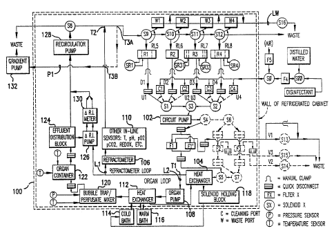
Figure 1 shows the overall fluidic circuit diagram of this invention.
Figures 2A-C show side, top and bottom views, respectively of a two-chamber
gradient former employed as reservoir Rl in this invention.
Figures 3A-C show side, top and bottom views, respectively, of a three-chamber
gradient former used as reservoir R3 in this invention.
2113119
-12b-
Figures 4A-C show front, side and rear views, respectively, of the HBM used in
this invention: Figure 4D shows the basic mixing unit area of the HBM; and
Figure 4E shows a top view of the base of the HBM.
Figure 5 shows the appearance of a typical protocol for introducing and
removing
cryoprotectant as viewed on the computer monitor during a perfusion.
Figures 6A-E comprise a flow chart of activities for organ cryoprotectant
perfusion.
Figures 7A-B comprise a flow chart of the procedure for non-cryoprotectant
perfusions.
Figure 8 shows the function (control of serum creatinine) of rabbit kidneys
transplanted after perfusion with VS4.
WO 93/00808 2 ~ ~ 311 ~ P~/US92/05711
-13-
Detar7ed Description of the Preferred Embodiment and Best Mode
In a preferred embodiment, the apparatus incorporating
the
principles and features of this invention is contained
in a refrigerated
cabinet 100 (shown by double dashed lines in Figure 1).
The refrigerated
S cabinet contains two sides, the reservoir/solenoid side
and the
organ/refractometer side. The cabinet ~ is faced with double
paned
transparent doors each containing approximately 1 inch
of insulating air
(which can be reduced in pressure and/or humidity if necessary)
between
the panes to avoid condensation of moisture on the doors
and to
minimize heat leak to the cabinet. The organ-side door
is split to form
a "Dutch door". This allows the upper portion of the organ-side
door to
be opened and closed to place the organ in the system and
to remove the
organ without changing the temperature below the upper
portion of the
door, where the organ container and most other equipment
is located.
The cabinet may also employ a "Dutch door" on the reservoir
side of the
cabinet to enable the operator to make any needed adjustments
(e.g., fluid
addition to the reservoirs, transfer of upper fluid lines,
etc.) without
disturbing cabinet temperature to an unnecessary degree.
The primary features of the invention and its mode of operation
are shown in the fluidic logic schematic of Figure 1. All
fluid available for
circulation through the system is drawn into the main circuit
by a circuit
pump 102 through fluid uptake lines U1, U2, U3, or U4 depending
upon
the computer-controlled actuation pattern of three-way
solenoid valves S1,
S2, and S3. Uptake lines U1-U4 connect either to fluid
delivery lines DI-
D4 leading from reservoirs RI-R4, respectively, or to cleaning
ports Cl-
C4, through standard tubing quick disconnects. By clamping
D1-D4 and
unplugging them from uptake lines Ul-U4, lines U1-U4 can
be plugged
into cleaning ports Cl-C4, as indicated by the curved arrows.
While this
is presently done manually, it will be appreciated by those
skilled in the
WO 93/00808 PCT/US92/05711
211311
-14-
relevant arts that appropriate valves, tubing and controls
could be added
to handle this task automatically.
In the embodiment of the invention as presently constructed,
the
reservoirs R1-R4 are supported on a thick transparent
plastic shelf from
which four magnetic stir tables hang which stir the four
reservoirs.
Thorough stirring of R1, R3, and R4 is necessary for proper
generation
of the desired concentration-time histories. The on/off
states and stir
rates of the stir tables are independently controlled.
Ports Cl-C4 lead to sources of sterile (distilled) water,
air, and
disinfectant. Solenoid valves SO and S00 are interposed
in the delivery
lines for these sources and are arranged to ensure that
traces of
disinfectant do not enter the perfusion system by accident.
Solenoid SO
controls whether air or fluid will enter the perfusion
circuit for cleaning,
while solenoid S00 determines whether the fluid selected
will be water or
disinfectant. The breakup of the main cleaning line into
four independent
channels outside of the cabinet rather than just before
reaching Cl-C4
ensures that each channel is independent of the others,
i.e., not subject
to any meaningful cross-contamination resulting from diffusion
of
unpurged solution backwards from the fluid uptake lines
U1-U4 into the
cleaning lines leading to cleaning ports Cl-C4.
Distilled water and disinfectant are drawn into the system
through
a sterilizing filter F4, while air is drawn into the system
through an air
filter FS. The disinfectant of choice at present is a
clinically accepted
dialysis machine cold sterilant such as Actril. The cleaning
procedure is
to wash the perfusate out of the system with water and
then to displace
the water with sterilant. Prior to the next perfusion,
the sterilant is
washed out of the system with water and the water is then
washed out of
the system with air. The system is then primed by displacing
the air with
appropriate perfusate. The air flush is used to avoid
the persistence of
any lingering traces of sterilant dissolved in the rinse
water, and to avoid
any possible dilution of the priming fluid with water
(i.e., to reduce the
.__. _ T. _ _.
WO 93/00808 21131.19 P~T/US92/05711
-15-
amount of priming fluid needed for displacing water from the system), to
allow a visual check of the completeness of priming, and to reduce
spillage of water in the cabinet when the reservoirs, filters, and organ
cassette are placed into the system after cleaning but before priming. The
air purge can, however, be omitted if desired. The air filter is used to
prevent contamination from pathogens in the air, if necessary.
Solenoid valves S9-S12 normally diiect fluid to reservoirs Rl-R4 or
to waste. Reservoirs R1-R4 can also be detached from the system by
removing recirculation lines RLS-RL8 from reservoirs R1-R4 and plugging
them into waste ports Wl-W4, respectively (as indicated by curved
arrows), allowing reservoirs R1-R4 to be removed from the system for
cleaning, sterilizing, and refilling. When reservoirs Rl-R4 are removed,
valves S9-S12 direct fluid to waste ports Wl-W4. The four waste lines
corresponding to waste ports Wl-W4 converge to a single common waste
line LW. A two-way solenoid valve S16 is located on the common waste
line. When the waste ports are not in use, the common waste drainage
line is blocked by closing valve S16 to prevent any possible backflow of
waste or pathogens into the sterile cabinet.
The use of this system of uptake lines U1-U4, which are plugged
alternately into reservoir delivery lines D1-D4 or cleaning ports Cl-C4, in
combination with recirculation lines RLS-RL8, which are plugged
alternately into the reservoir internal return lines (not shown in the
figure) or into waste ports Wl-W4, allows complete sterilization of the
perfusion circuit. The blunt ends of the uptake lines U1-U4, delivery lines
Dl-D4, cleaning ports Cl-C4 and waste ports Wl-W4 may be sterilized
by swabbing with disinfectant when the tubing is being transferred from
one alternative position to the other. The tubing transfer is accomplished
while applying digital pressure to the tubing so as to occlude it while
making the transfer to prevent fluid leaks and further reduce the risk of
contamination.
WO 93/00808 PCT/US92/05711
2113119
- -16-
The fluid withdrawn from reservoirs Rl-R4 or from ports Cl-C4
is delivered through one of several filters Fl, F2, and F3, depending upon
the state of actuation of solenoid valves S4 through S7. These actuation
patterns will be described in more detail below. Experience has shown,
however, that a single filter Fl or two filters Fl, Fl' in parallel will be
adequate for most studies (rendering valves S4-S7 optional, as indicated
by broken lines) since virtual step changes in concentration can be
imposed even when only one filter or two filters in parallel are present in
the circuit.
It is desirable to minimize the distance between the circuit pump
102 head and the solenoids Sl-S7 to minimize circuit dead space and dead
time and minimize the effects of perfusate viscosity.
The filters are capable of sterilizing the perfusate and are
autoclavable. All filter holders can be removed from the system for
cleaning and sterilization by means of the quick disconnects shown in
Figure 1. Vent lines Vl-V3 lead to solenoid valves S13-S15, located
outside of the refrigerated portion of the cabinet 100. These vent lines
are opened and closed under computer control during priming and
cleaning of the system to permit air to escape and thereby prevent the
filters from becoming blocked or damaged. A manual bypass (shown only
for the S13 bypass) is provided for V1-V3 for emergency purging of air
from the circuit. Obviously, air purges of the system beyond filters Fl-F3
are not possible if filters Fl-F3 are present in the circuit; hence filters Fl-
F3 must be removed before beginning the washout of sterilant if an air
purge is to be included in that procedure.
In the presently preferred embodiment, a 90 mm diameter filter of
0.22 micron pore size is located in each filter holder. This size filter is
able to pass enough vitrification solution at 0°C to permit the
successful
perfusion of a rabbit kidney, with an overlying 1.2 micron filter and a
coarse prefilter to prevent clogging. The standard configuration for the
operative version employs two identical filters in parallel. This is
WO 93/00808 2113119 P~/US92/05711
-17-
necessary to accommodate the flows required for human organs and
provides a safety factor for any air which may be inadvertently introduced
into the arterial fluid, as well as minimizing pressure building proximal to
the filter. This continuous filter sterilization and resterilization of the
S perfusate during the perfusion can serve as a back up for pre-sterilized
solutions in case of contamination for any reason during the perfusion.
Once the fluid from the selected reservoir has passed through the
appropriate filter, it goes through some preliminary temperature
conditioning in a heat exchanger 104 and then travels to a position as
close to the organ as possible, at which point it encounters a "T' type
tubing connector Tl. The bulk of the flow passively takes the path Ll
("refractometer loop") that leads to a flow-through process control
refractometer 106 that measures the index of refraction of the liquid and
hence the cryoprotectant concentration. The remainder of the flow is
directed through an organ loop L2 by means of an organ pump 108. The
organ pump speed is controlled by the computer so as to maintain the
desired organ perfusion pressure despite wide variations in the organ's
vascular resistance. By changing the organ pump head and the diameter
of the tubing going through it, a wide range of flows can be generated
sufficient to perfuse organs of a wide range of sizes: organs as small as rat
hearts and as large as human kidneys have been successfully perfused.
The flow rate delivered by the circuit pump 102, which supplies
both the refractometer loop Ll and the organ loop L2, must be high
enough to both exceed the flow rate through the organ at all times and
2~ to ensure that sufficient flow is available for the refractometer 106 and
other in-line sensors, generally designated 110, for measuring temperature,
pH, and other desired parameters of the perfusate to permit accurate
measurements. The flow must also be high enough to minimize the "dead
time" between changes in reservoir concentration and changes in the
sensed concentration and other sensed parameters in the refractometer
loop as well as to minimize the "dead time" between the reservoir and the
WO 93/00808 PCT/US92/05711
211311 ~
-18-
organ. The circuit pump flow is limited by the need to prevent fluid from
being delivered to the filters at a rate in excess of what these filters or
the
tubing leading to them can pass without failing, as well as by constraints
of heat output and wear and tear on the circuit pump tubing. The speed
of the circuit pump is usually not varied during an experiment and does
not therefore usually require computer control, though computer control
is available as an option.
After passing through the organ pump 108, the perfusate passes
through a second heat exchanger 112 that finalizes perfusate temperature
conditioning. This is done by adjusting the flow of both cold and warm
liquid from cold and warm baths 114, 116, respectively, using computer-
controlled pumps (not shown) between heat exchanger 112 and baths 114,
116.
The computer is able to vary flow through both the cold path and
the warm path so as to adjust perfusate temperature in the arterial line
and therefore also in the effluent of the organ. The arterial and effluent
temperatures provide an indication of the actual organ temperature. By
controlling the flow rate of cold and warm bath fluid, organ temperature
can be adjusted independently of organ flow, provided flow is not close
to zero. Experience has shown that arterial and venous temperatures at
least as cold as -6°C and at least as high as 25°C can be
achieved with
this invention. Generalized cabinet cooling is not an alternative to the
heat exchange system for subzero perfusions because cooling of the
cabinets to subzero temperatures will cause freezing of the more dilute
solutions in the tubing lines. Specific jacketing and cooling of the organ
container is of theoretical value, however, and may optionally be included.
The temperature-conditioned perfusate is then debubbled and
mixed in a bubble trap/mixer 120 just before entering an organ container
122. Arterial and venous temperature probes, generally designated "T' in
Figure 1, penetrate the wall of organ container 122 through simple holes.
Pressure and, optionally, temperature is sensed in the bubble trap.
.. .. _._.__. T.~ _. _
WO 93/00808 ~ ~ (~ PCT/US92/05711
-19-
Although shown separately in the drawing for ease of understanding, the
bubble trap and mixer 120 are in fact an integral part of the heat
exchanger 112, so heat exchange continues to be controlled while
debubbling and mixing are accomplished. Experience has shown that
mixing is important due to the tendency for layering of dilute solutions on
more concentrated, denser solutions. Details as to the specific
construction of the heat exchanger/bubble trap/mixer (HBM) are
described below.
Under normal circumstances, the cooling fluid effluent from this
second heat exchanger 112 is used to cool the perfusate passing through
the preliminary heat exchanger 104. This cooling fluid then travels to a
solenoid holding block 118 physically containing solenoids S1-S12, so as
to draw off waste heat from these solenoids before returning to the cold
bath.
The holding block 118 is equipped with an internal fluid path for
drawing off waste heat from the solenoids and may be either metal or
plastic. The solenoids are preferably 3-7 watt (or less) piston type 3-way
solenoids of minimal internal fluid volume having orifices on the order of
0.156 inches or more and Cv values > 0.16 or more (e.g., NR (Neptune
Research) Model 648T033 fitted with RC dropping circuits and 3-watt
coils) while resisting pressures of up to 500 mmHg or so. Solenoids
having 1/16 inch orifices and Cv values of 0.01 to 0.03 (e.g., Valcor's
Model 20-2-3) are not fully satisfactory due to the high viscosity of the
solutions used for cryopreservation (causing difficulty aspirating viscous
fluid through S1-S3), the high flows desired for controlling dead times and
for perfusing larger organs, the possibility of clogging, and the buildup of
pressure between the circuit pump and S8-S12. The detailed actuation
pattern and tubing arrangement of the solenoids is described below. The
internal solenoids not held in the solenoid block, SR1, SR31 and SR32,
are described in more detail below.
WO 93/00808 PCT/US92/05711
211319
-20-
A stopcock (not shown) in one of the coolant lines permits
the in-
line heat exchanger to be bypassed if desired. When the
cooling function
of the solenoid holding block 118 is in use, the effluent
is directed to the
solenoid holding block cooling system before returning to
the cold bath.
An effluent distribution block (EDB) 124 (Figure 1) is connected
to the output side of the organ container 122. The EDB is
designed so
that a small amount of effluent is always' present at the
bottom of the
block. This effluent or residual fluid is withdrawn by the
two-channel
"delta R.I. pump" 126 and sent to the differential refractometer
("delta
R.I. meter") 130 where its refractive index is compared
to that of the
arterial perfusate from refractometer loop Ll (pumped at
the same rate
as the venous effluent sample) and a difference signal generated.
EDB
124 is drained also by the effluent recirculation pump 128.
The EDB 124
therefore allows effluent to be recirculated with or without
first being
delivered by the delta R.1. pump 126 to a differential refractometer
130.
The differential refractometer 130 sends a signal to the
computer which
provides a measurement of the difference in concentration
between the
fluid in the refractometer loop Ll and the organ effluent
in the organ
loop L2. The nonlinear baseline resulting from this unorthodox
use of the
differential refractometer is accounted for in the software
for running the
perfusion program. Since the fluid in the refractometer
loop will
approximate the concentration of the fluid entering the
artery of the
organ, the delta R.I. output provides an estimate of the
arterio-venous
concentration gradient across the organ. When this gradient
is large (in
either the positive or negative direction), the organ is
far from
equilibrium. When the gradient is zero, the organ is at
least largely in
osmotic equilibrium with the perfusate.
All effluent from the organ (together with the arterial
fluid
sampled by the delta R.1. pump) is ultimately collected
by the
recirculation pump 128 and sent to solenoid S8, which controls
whether
the effluent is recirculated to the reservoirs or discarded
to waste.
WO 93/00808 PCT/US92/05711
211311)
-21-
Effluent to be returned to a reservoir is combined with the fluid flowing
through the refractometer loop Ll at a T connection T2. As noted above,
return to the correct reservoir is then controlled by the actuation of
solenoids S9 through S12.
The recirculation pump 128, like the circuit pump 102, need not
require flow adjustment. It is normally set to a rate sufficient to exceed
the maximum steady flow through the organ pump 108. Since the output
of the recirculation pump exceeds that of the organ pump, air is
continually introduced into the tubing leading to solenoid S8 and usually
to the reservoirs Rl-R4. Provisions to prevent excessive bubbling of the
reservoirs as a result of this are described below.
Although the delta R.I. pump speed can be changed, it is usually
kept constant throughout an experiment. In the presently operative
version, it is not under computer control, but computer control would be
a desirable option in some cases. The delta R.I. pump employs very small
diameter tubing to reduce delays in fluid transit time. This small tubing
is particularly important because the flow rate through the delta R.I.
circuit is limited by the lowest flow rate through the organ, which may be
small, and by the limited size of the fluid paths in commercially available
differential refractometers.
The return of the differential refractometer output to the organ
effluent line is proximal to the effluent recirculation pump. This
placement rather than placement distal to the pump ensures a steady flow
though the differential refractometer, whereas distal placement may
prevent or alter differential refractometer flow by virtue of a higher exit
pressure.
The present operative version of the embodiment of the invention
uses silastic tubing of 1/8 inch diameter throughout the system, which is
sufficient to accommodate the needed flows and is preferred. Silastic is
compatible with Actril cold sterilant, is translucent (important for
visualizing flow to detect problems and for observing any signs of
WO 93/00808 PCT/US92/05711
211311
-22-
microbial growth), is impervious to common cryoprotective agents such as
dimethyl sulfoxide, and is soft enough to be easily manipulated. However,
silaslic should not be used in circuits coming into contact with silicone
cooling fluids, which swell and weaken silastic tubing.
Reservoir R1 is constructed as a gradient former (Figure 2).
Essentially the gradient former consists of two concentric cylinders, an
outer cylinder 200 and an inner cylinder 201. A fluid path 205 allows
fluid to flow from the outer cylinder 200 to the inner cylinder 201 under
the influence of gravity in response to a reduction of volume in the inner
cylinder. The concentric orientation of the fluid compartments is very
space efficient. The fluid delivery line 204 corresponds to the line Dl of
Figure 1. The unit shown is a modification of a commercially available
gradient former. The necessary modifications for use with this invention
are as follows.
1) The stopcock normally used to control flow from the outer
cylinder to the inner cylinder in the commercial device is replaced by a
pinch-type two-way (on/off) solenoid valve 202 (currently, a Bio-Chem
Valve Corp. model 100P2WNC). The pinch-type valve is preferable for
this application to a piston-type valve because of the small pressure
difference available to drive fluid flow and the consequent need for a
large working diameter fluid path. It is also preferable for easy removal
from its tubing when the reservoir is to be removed from the cabinet for
cleaning, leaving the solenoid behind. The base of the gradient former
has been modified, at 203, to make room for the solenoid and to support
it on a platform so as to keep the solenoid oriented correctly. The
solenoid is located a sufficient distance from the reservoir to avoid
excessive heating of the reservoir fluids.
2) The diameter of the fluid path 205 from the outer cylinder
200 to the inner cylinder 201 has been enlarged to permit flow at an
adequate rate of the viscous solutions required for organ cryopreservation.
An inner diameter of 1/8 to 3/16 inch is adequate.
_ _~._.~ .__ ~_
WO 93/00808 2 ~. I 3 ~ 1 g PCT/US92/05711
-23-
3) A lid 206 has been provided. The lid has an outer overhang
207 that prevents the lid from moving from side to side after it is placed
on the cylinder. The lid has built-in outer and inner filling funnels 208a
and 208b and a recirculation port 209.
4) Funnels 208a and 208b extend into respective internal fill
tubes 210a and 210b. The internal fill tubes are preferably rigid hollow
rods located next to the wall of the inner and outer cylinders and
perforated at 1-2 cm intervals with holes 211a and 211b, respectively,
which are approximately 3 mm in diameter. The function of the fill tubes
is to reduce the creation of bubbles as recirculating fluid impacts the
surface of the liquid in the reservoir. The purpose of the perforations is
to enable air to escape from the tube through the perforations so as not
to force air to the bottom of the reservoir to form bubbles. These
functions are particularly important in perfusates containing protein,
which tend to stabilize bubbles.
5) A fill mark has been provided to enable the reservoir to be
filled reproducibly to the same, predetermined volume. The operator can
establish his/her own fill mark depending upon the details of the
application. The gradient formers have approximate graduations
(horizontal lines on both the inner and outer cylinders, aligned so as to
permit avoidance of parallax error in reading the liquid level in either
cylinder) spaced approximately 0.5 cm apart for a 2 liter gradient former.
These graduations are also important for establishing slight, deliberate
mismatches in liquid Level between inner and outer cylinders, which are
necessary to prevent premature mixing of solutions of widely differing
densities, such as cryoprotectant-free perfusate and vitrification solution.
They also permit a rough quantitative check by the operator on the
progress of the gradient as represented on the computer screen.
6) The plastic composition of commercially available gradient
formers may create problems for certain types of cryoprotectant, which
could conceivably attack the plastic. It is therefore preferred to use
WO 93/00808 PCT/US92/05711
211311_ J -24-
reservoirs made of transparent material (e.g., glass, plexiglass
or the like)
that is compatible with the cryoprotectant chemicals or
use reservoirs
whose surfaces have been siliconized or otherwise treated
to prevent the
attack. In the inventors' experience, acrylic has been
found to be an
S acceptable material.
7) The reservoir R1 contains a stir bar 212. The stir bar
is
housed in a jacket 213 attached to a freely spinning vertical
pin 214
extending to the stir bar from the lid of the reservoir
to prevent the
jacket, and hence the stir bar, from moving laterally.
This change is
necessary to make sure chattering, and therefore poor mixing,
does not
occur while the perfusion machine is unattended. Support
from above
rather than below prevents unnecessary perfusate frictional
heating and
avoids drainage/cleaning problems.
Reservoir R3 is also constructed as a gradient former.
The details
of reservoir R3 are shown in Figure 3. In the drawing,
those elements
that are substantially the same as in reservoir Rl are
designated with the
same reference number, except that the first digit has
been changed from
a "2" to a "3". Reservoir R3 contains an outer compartment
315 (R33), an
inner compartment 318 (R3~), and a third intermediate compartment
316
(R32). Intermediate compartment 316 is connected to inner
compartment
318 through a fluid conduit 320 controlled by a solenoid
317 (SR31).
Compartment 316 also connects to outer compartment 315
by a fluid
conduit 321 controlled by a solenoid 319 (SR32). The use
of an outer
compartment is necessary when concentration is being reduced
to zero or
nearly zero, for reasons noted below in the discussion
of the function of
the gradient pump and the action of the gradient formers.
The outer
compartment is necessary in preference to a larger volume
of fluid in the
middle compartment because increasing the volume of fluid
in the middle
compartment will cause the concentration profile of fluid
flowing from the
gradient former to waste in response to a constant efflux
rate of inner
cylinder fluid to become non-linear, therefore making control
of
WO 93/00808 211311 ~ P~/US92/05711
-25-
concentration-time history more complicated. More importantly, an
excessive amount of fluid in the middle compartment would be required
to approach a zero concentration in the circuit compared to the amount
of fluid required in the outer compartment after virtual emptying of the
inner and middle compartments.
Automated use of reservoir R3 poses some problems which are
successfully addressed in part by software and in part by the specific
construction of R3. Specifically, actuation of solenoid SR32 allows fluid
in the outer compartment (R33) to flow first into the middle compartment
(R32) and from this compartment to the inner cylinder (R31). This is
because the pressure head present between R33 and R32 is large when
R31 and R32 are nearly empty, which occurs when SR32 is activated. At
this point, R33 is still full. This large pressure head causes fluid to flow
too rapidly into R31 if R33 is connected directly to R31 rather than using
R32 as a buffer between R33 and R3~. By adjusting the level of R33, the
flow can also be partially controlled. But even with these two precautions,
further control of flow is required by using an appropriate duty cycle for
SR32. The flow to R31 should be slow at first and more and more rapid
as the concentration is brought closer and closer to zero, whereas passive
flow under the influence of gravity will always be fastest at first and
slowest at the end unless the flow is metered by the sort of tailored duty
cycle currently being imposed on SR32.
The other modifications to R3 resemble those of R1.
Reservoir R4 is a gradient former constructed in the same manner
as R1.
An important element of the fluidic circuit is the gradient pump
132 connected to the circuit by a line P1 (Figure 1). The function of the
gradient pump is to allow for gradual changes in concentration within the
appropriate reservoirs within the cabinet. The method by which this is
accomplished will be described below. The placement of the line P1 to
the gradient pump at T3A, just after the point of joining of the
WO 93/00808 PCT/US92/05711
213.311 J
-26-
refractometer loop Ll and the organ loop L2, presents one option for
ensures removal of some of the air introduced by the organ effluent
recirculation pump 128 and therefore helps reduce bubbling of the
reservoir fluid.
S A better option, however, and the one presently in use, is to draw
no air into line P1. This is accomplished by connecting P1 at point T3B
and results in fully controlled concentration-time histories. The bubbling
problem is then overcome by continuously regulating the speed of the
recirculation pump 128 to be just slightly in excess of the combined flows
of the organ pump 108 and the delta R.I. pump 126 so as to introduce
little air. Attaching the recirculation output of S8 directly to Pl without
regulating the speed of pump 128 results in degraded concentration
history and is not recommended.
The purpose of the gradient pump 132 is to remove some of the
recirculating fluid from the circuit. This removal of fluid causes the flow
rate of fluid back to the reservoir of origin to be less than the flow rate
of fluid from this reservoir to the circuit. This causes the level in the
inner cylinder of the reservoir (R1, R3, or R4) to go down. This lowering
of inner cylinder fluid level in turn causes the fluid in the outer or middle
compartments to flow into the inner cylinder to keep the two levels
similar. Thus the two dissimilar concentrations in the two cylinders are
mixed in the inner cylinder, generating the concentration gradient which
is then sent to the rest of the circuit. This is the manner in which the
gradient pump effects the desired gradual changes in concentration which
reach the organ and the refractometers. Any necessary adjustments to the
gradient pump speed are made by the computer.
The principle involved is that of an ordinary linear gradient former
in which the portion of the circuit external to the gradient former can be
regarded, to a first approximation, as extra volume in the inner cylinder.
Withdrawal and discard of fluid from the inner cylinder at a constant rate
will result in a linear molar concentration increase with time despite the
WO 93/00808 ~ 11311 ~ P~/US92/05711
-27-
presence of the rest of the circuit and the recirculation of fluid back to
the reservoir. However, unlike an ordinary gradient former, the
concentration of fluid leaving the gradient former at the moment the
volume in the gradient former becomes zero will not be equal to the
concentration of fluid in the outer (or middle) cylinder of the gradient
former. Therefore, in order to approach a concentration of zero during
cryoprotectant washout using an ordinary two-compartment gradient
former, it is necessary to add additional fluid to the outer cylinder while
continuing to discard fluid from the inner cylinder normally. This is why
R3 has been modified to have a third compartment: the extra fluid
required to continue cryoprotectant washout can be added from this third
compartment by the computer without operator intervention which could
compromise temperature control and introduce inaccuracies. During
introduction of cryoprotectant, on the other hand, the desired final
concentration can always be reached by using a concentration in the outer
compartment which significantly exceeds the final concentration desired
in the circuit at the end of the gradient.
The HBM heat exchange system is shown in detail in Figures 4A-
E.
Perfusate enters the HBM through an entry port 403, travels
through a central channel 400, and leaves the HBM via an outlet port
406. On either side of the central perfusate path are separate chambers
for regulating temperature. The two innermost temperature control
chambers 401 (one on each side of the perfusate path) are used for the
circulation of coolant, while the outer chambers 402 are a pathway for the
flow of room temperature fluid for offsetting the coolant. (For
specialized applications involving, for example, normothermic perfusion,
these pathways can be reversed.)
The direction of cold fluid flow is optional. Adequate temperature
control has been found when all fluids (perfusate, coolant, and warming
fluid) flow in the same direction (uphill) despite the lack of
WO 93/00808 PCT/US92/05711
2113~.~.~
-28-
countercurrent heat exchange. This mode allows the avoidance of air or
carbon dioxide accumulation in the outer chambers.
Perfusate enters the bottom of the HBM unit through inlet 403 and
travels upward in a zig zag pattern. It emerges into a small upper
reservoir which has an air space above: this is the bubble trap area 404.
Perfusate then travels beneath the bubble trap and goes through a
perfusate mixing area 405 before finally traveling onward to the arterial
outlet.
The inlets for cold 407 and wane 408 fluid are each split into two
channels within the base of the unit. The outlets 410, 411 for warm and
cold fluid, respectively, each receive fluid collected from two channels
such that each channel of the same kind (i.e., each cold channel or each
warm channel) is the same length and nominally experiences the same
pressure difference from start to finish, so that flow rate through each like
channel should be approximately equal.
All of the cold and warm fluid pathways include a length of flexible
tubing 412 at the rear of the unit. These tubing segments serve two
purposes. First, by introducing an air gap between the four channels, heat
exchange between them is minimized. This is particularly desirable when
all of the cold and warm fluid is flowing in the direction opposite to that
of perfusate flow (i.e., in orthograde direction) and has not already
undergone heat exchange with the perfusate. Second, each tube can be
clamped. In this way, if by chance one cold channel or one warm channel
should take all of the cold or warm fluid delivered while the other channel
"airlocks", this situation can be corrected by clamping the channel
receiving all of the flow and purging the air out of the inactive channel,
bringing each channel into full function and equal flow.
Because in orthograde mode the temperature conditioning fluid
enters the heat exchanging portion of the unit at the top and exits at the
bottom, it is necessary upon installation to run the cold and hot pumps in
retrograde direction in order to purge all air out of the cold and warm
__..__~~~.._ T_. _ _ _
WO 93/00808 ~ ~ ~ ~ PCT/US92/05711
-29-
channels. This is best accomplished if the cold and warm tubing leading
to and from the bath is no more than about 1/8 inch in internal diameter,
since at this diameter fluid flow will displace air from the tubing rather
than allowing it to flow uphill in a direction opposite to the direction of
fluid flow or otherwise. to remain unpurged in various parts of the tubing.
Thus, when the pump direction is reversed again from retrograde to
orthograde, no air will be present in the tubing and none will be trapped
in the heat exchange chambers of the unit.
In addition to serving a heat exchange function, the zig zag pattern
is also designed to force mixing of previously perfused dense perfusate or,
when perfusate density is rising rather than falling, to purge the less dense
perfusate from the perfusate path.
As the perfusate emerges from the zig zag heat exchange area, it
enters the bubble trap 404 at trap entry area 418. Perfusate exits the
bubble trap through exit region 419. The zig zag pattern, in fact, is also
designed to allow any air bubbles to exit the heat exchange area and to
emerge into the bubble trap area. The bubble trap area is designed to
have the following features.
1. Its volume is sufficiently large to reduce the pulsatile action
of the perfusion pump to a minimum by distributing the shock of each
stroke over a relatively large air volume. This simplifies pressure control
and measurement and may be less damaging to the organ.
2. Its volume is sufficiently low to minimize the liquid volume
present in the trap and thereby to minimize the dead time and dead
volume between the organ pump and the organ itself. A minimal volume
is also desirable to minimize layering of more dilute perfusate over more
dense perfusate.
3. A pressure sensing port 413 is provided. Port 413 has no
fluid connection to the perfusate, thus eliminating a "blind alley" in which
fluid cannot be mixed properly or in which disinfectant might fail to
penetrate or might be trapped.
WO 93/00808 PGT/US92/05711
211311 -30-
4. The lid 414 of the trap is removable for cleaning.
5. A vent port 416 is provided which is used to adjust fluid
level- in the trap so as to make it the minimum required to serve the
bubble trap function and to maximize pressure wave damping. The tubing
from this vent leads to the outside of the cabinet, permitting adjustments
to be made without opening the cabinet door. The same port leads to the
electronic pressure transducer as well.
6. A third port 417 is provided through the bubble trap lid to
permit the injection of drugs, vascular labeling materials, fixative, etc.
7. The walls of the bubble trap are angled near the trap entry
and exit points 418, 419, respectively, to produce a certain amount of
mixing of the perfusate both as it enters and as it leaves the trap, and to
break up and minimize the volume of layers of dilute perfusate overlying
more dense perfusate.
8. The option exists of introducing probes, such as a
temperature probe via one of the ports in the trap lid to make
measurements in the perfusate without permanent embedding of the
sensor: the port consists of flexible tubing attached to a plastic threaded
fitting. A probe can be freely admitted or withdrawn and the tubing
clamped with hemostats or an equivalent clamp to effect a pressure-tight
seal. This simplifies removal and reinstallation of the HBM when it must
be cleaned and allows flexibility in probe selection and the opportunity of
using the probe for other measurements elsewhere.
After leaving the bubble trap, the perfusate descends to a mixing
area 405 (see Figure 4D). The basic unit of the 3-unit mixing path is a
narrow horizontal entry area HE emerging into a "wide" basal area BA
which rises to an area of flow restriction FR and ends in a descent D to
the next horizontal entry area. Fluid entering HE is forced through an
opening too small to support much layering of low density fluid on top of
high density fluid, especially considering the right angle turn required just
before HE. Fluid flowing into BA may, if less dense, rise immediately
_ ~__~_~.~._ ~.. t
WO 93/00808 ~ ~ ~ PCT/US92/05711
-31-
upward toward FR. If more dense, it may be driven into the wall W and
rise upward along this wall. Upon encountering FR, however, the denser
liquid will be accelerated toward the less dense liquid rising directly from
HE, creating turbulence and mixing. If BA fills with dense perfusate, the
speed of the fluid emerging at FR directly upwards toward D should
cause the dense liquid to mix with any low density fluid layered above FR.
Furthermore, the narrow descending path D should draw layered liquid
down the angle along with denser liquid, again preventing stagnant layers
from persisting. In practice, three such mixing units aligned in series as
shown in Figure 4B are sufficient to mix initially very poorly mixed
perfusate, which is encountered frequently in the course of abruptly
raising or lowering cryoprotectant concentration. One final function of
the mixing units is to serve as a trap for any small bubbles which for any
reason are not removed in the bubble trap area. (Bubbles in the mixing
area are, however, easily purged by the operator prior to initiation of
organ perfusion.)
After leaving the mixing region, the perfusate descends to an outlet
port 406 leading directly to the organ. The path from the final mixing unit
to port 406 is deliberately created at an angle to the horizontal in order
to provide one last chance of stopping any bubbles from reaching the
organ, since in order to reach the organ a bubble in this pathway would
have to flow downhill, contrary to its tendency to flow uphill.
The mixing area and subsequent areas are purged of air by
occluding the outlet tubing affixed to port 406 with the vent open until
approximately 1/2 inch of fluid has accumulated in the bubble trap. The
vent is then closed until the pressure has reached about 60-120 mmHg.
Finally fluid is once again allowed to flow freely through port 406. The
jet of fluid through the mixing area and out port 406 sweeps all air out of
the fluid path from the bubble trap to port 406. If some air persists, it
can be removed by repeating the process. After air has been purged, the
vent is opened to allow unnecessary fluid in the bubble trap to exit the
WO 93/00808 PCT/US92/05711
21~31~~ -32-
trap under the influence of gravity, reaching a final depth of about 1/8
inch. A final depth of 1/8 inch cannot be set before purging the line of air
because insufficient volume exists to avoid refilling the mixing area with
air from the bubble trap during the purging process.
The HBM is designed to require removal for cleaning only
infrequently. Disinfection and removal of disinfectant from the bubble
trap area is effected automatically but ~ does require some operator
attention afterwards to ensure that all uppermost exposed surfaces are
disinfected and later washed free of disinfectant without contaminating
the outlet tubes.
After the perfusate exits the HBM unit through port 406, it enters
the organ in the organ container 122. In the preferred embodiment, the
organ container comprises a rectangular box with a hinged lid, lid stop, lid
handle, sloped floor, specially sloped feet, arterial and venous
thermocouple inlets, perfusate inlet, and effluent outlet in the foot
opposite the inlet. The slope of the floor is downward in both the right
to left and the back to front directions to ensure that all fluid runs to the
foot outlet with very little fluid accumulation anywhere in the container.
One needle probe is inserted directly through the wall of the arterial line.
A second probe is placed directly in the stream of fluid emerging from the
organ. In typical results, the arterial and venous temperatures differ by
only tenths of a degree, but both are useful for quality control. The organ
container may employ a soft mesh support for the organ similar to that
used in the Waters organ cassette or the organ can be placed directly on
the floor of the organ container or on a specially designed independent
and removable support.
The organ container 122 and the organ pump 108 are placed in
maximum proximity to reduce dead times and dead volumes between the
two, and the tubing leading from the organ pump to the organ container
is chosen to be as small in inner diameter as possible for the same reason.
___________ ___.__~_ ~. _____ _
WO 93/00808 ~ ~ ~ PCT/US92/05711
-33-
Most perfusate does not go through the organ loop L2 as described
above but travels instead from the filters to the in-line analogue
refractometer 106. The presently preferred embodiment of the invention
uses a modified commercially available refractometer from Anacon
S corporation. In particular, small diameter tubing inlet and outlets are
used rather than the very large standard Anacon pipe fittings.
The modification of the refractometer sensing head appropriate for
the final invention could contain the following changes from the ordinarily
available Anacon unit.
1. The internal volume of the fluid path could be kept to a
minimum.
2. Presently, it is necessary to purge the air space of the unit
with a slow flow of dry nitrogen gas to prevent condensation of moisture
due to the low temperatures and high humidities prevailing in the cabinet.
In a modified version, the electronics area of the sensing device could be
hermetically sealed with some desiccant inside to eliminate the need for
a nitrogen purge.
The invention allows the operator to access reservoirs in any
sequence and to otherwise custom-design the process which may be of
interest. The operator is even free to switch solenoid positions depending
on what he may want to do. Nevertheless, the following nominal
application illustrates the actuation patterns required to deliver fluid from
and to each individual reservoir and filter. It also illustrates the "standard
protocols" for organ cryoprotectant perfusion and for cleaning of the
2s system which the system was designed primarily to carry out.
Solenoid S1 admits fluid from R1 when off, or from R2 when
activated. Solenoid S2 is open to R3 when not energized, or to R4 when
energized. The output of S1 and S2 is to S3, which accepts fluid from S1
(that is, from R1 or R2) when in the resting state and which accepts fluid
from S2 (i.e., from R3 or R4) when activated. The common outlet for S3
WO 93/00808 PCT/US92/05711
~~1~~~~ -34-
(always open) leads to the circuit pump 102, which then withdraws fluid
from the solenoid-selected reservoir.
If differential filters are to be included, then the output of the
circuit pump 102 is to S4's common port (always open). When S4 is not
energized, its output is directed to filter Fl. The return from filter Fl
returns to the normally open port of SS and exits through the SS common
outlet to the refractometer loop Ll and the organ loop L2. If, on the
other hand, S4 is energized, then its output is directed to the common
inlet port of S6. When S6 is in the resting state, its output is directed to
filter F2, and the return from filter F2 enters S7 through its normally
open port. The output from S7 travels to the normally closed port of S5,
which must be energized to accept this output. Once fluid has entered SS,
it flows out the SS common outlet to the refractometer loop and the
organ loop. Finally if S4 is energized and S6 is also energized, fluid will
be directed through both of these valves and will reach filter F3. The
return from filter F3 occurs via the energized S7 and the energized SS
solenoids and goes to the two loops Ll and L2 as above. As noted
earlier, the use of filters F2 and F3 and therefore of solenoids S4, S5, S6,
and S7 is optional and will be useful primarily when very abrupt changes
from one solution to another are required, or when particularly heavy
particulate contaminates must be removed.
Effluent from the organ eventually returns to S8. If S8 is activated,
the fluid is discarded. If S8 is not activated, the fluid is directed from S8
to combine with fluid from the refractometer loop and returned to a
desired reservoir.
Fluid traveling through the refractometer loop travels successively
to solenoids S9 S10, S11, and S12 and then to waste if none of these
solenoids are energized. Energizing S9 diverts flow to the R1
recirculation line. S10's activation (in the absence of activation of S9)
diverts flow to R2. Similarly, selective activation of S11 or S12 will,
respectively, recirculate fluid to R3 or R4.
__________.____..T_
WO 93/00808 ~ ~ ~ ~ ~ ~ PCT/US92/05711
-35-
There are two basic processes of solenoid-actuated fluid control,
one for actual perfusions and one for system cleaning and priming. The
perfusion process typically proceeds from Rl through R4 whereas priming
must occur in the reverse order to load the fluid uptake and fluid
recirculation lines for reservoirs R2-R4 and, optionally filters F2 and F3
and their associated lines) while leaving the circuit primed with fluid from
(typically) Rl (or Cl) at the end of the priming (or cleaning) process.
The typical sequence of solenoid activations required to prime the system
(or to clean it) is as follows.
When only Fl (not F2) is present, priming (and cleaning) may
proceed in any order of reservoirs, provided, in the case of priming, that
the final reservoir corresponds to the first reservoir used for the
subsequent perfusion.
SOLENOID CONTROL SEQUENCE for STANDARDIZED
RINSING/PRIMING
(Uses: remove perfusate with filter-sterilized HBO at end of experiment;
replace cleaning H.,O with chemical sterilant solvent between perfusions;
remove disinfectant using filter-sterilized distilled HBO; remove water
using air; remove air using reservoir fluid, i.e., prime the system.)
WO 93/00808 PCT/US92/05711
2113119 -36-
to V7 V '~
x ~ 0
''r ~ C
M .~ t a . , , U ..' ~ ~
r x ~r w , O C y
x
. , , c
. a~ ~ ay ."'. C
~ O
~ . 00
0.. C
O
N + ~ ~ p
~ '
, . . , , . . N ~ y ~
, C
~
:9 C. c9 ~
y
+ .. v G
.
. , , , 3 G ci
. ,
.
O g-o ~ ~ o
,
o , + , ,
,
Li~ + '~ ~ : '~ '~' >,
" ~ ~~ ~
~O~_
+
00 , , , . , . , 3
.
II p = Cn ,~
~
r G
+ + + v ~3 ,
~ . , . , . ~
' ,
'
' _ ' ~ ,...
v
D . _
~o . . + + . . , . ~3 ~~ c ~ ~
, c
c ~n 4.
V
O v c~ o o
S~ ~
Z 1r + + + + i , ' CJ
, f
v ~
i , i G ~
.
.
.~ ~ 3 _ .. c
3
,
;
cn .~ ~ en .c
:.
c~ ? ~ o
+ + + + , :J ~ _ '':
j
, . . _
, ~
V U
G " ~
C ~ ~ O ~ 0.
,...:
N + + , n , , , n ~_ c.. v; a0 O
. r a)
i
O
y ~' G C~
~
+ + v ~ _
~ > v
.-., , . , , , , .. ~ C~
~. v C4 E
v: c~ ~_ :~
'? .3 -~ ~
i
i - r-
5
=
c 3 ~ ~ _ >, s
~ ~
c ,.. ~ ~~.~ '~ 3
ov;
o L. 3 ~ ~ ~ v
' '
~
b4 QO - ~ v: = _
'~
~ ~ , "~py'.~
%~c~
~ rr~ ~ s.J ~ ;J .T~.
C = 'n .'~
'~7 ~_'.. .. ~ fJ pD CJ C ~C"'""
~ ~ ~
O ~
O ~ /~ a0 e _ _ ~ ~
0 _ _ V%
~r J v ~ a
~ yr G ~ _ _ ~ U ~ ~_ r ~ ~C_
v
G. ~ ~ V ~ -~-~ ~ ~ ~
~
3 ~' c o
o
.
p c ~ '~- v ~ -' ~ v' G" 3 _y
~ p ~ c '?
J ~ . ~ J ~_ ,~, .. j, ~ O
U ;J V.' y v~
C V V ', 'U ~ y N ca ~
~ R ~ GJ
V .r ~
~
U ;J ~' -' ~ C O
~' a~
v W ' ' _ _ O ...
~ ~ p
= ~ ~ " ...
, w.~ U v;~ U v . J 4~ 3 p U
~ tn ,.r, C .C
,....
7 7 ~ ~' ~ '. v R ~ ca
~ ~ '
~ ., v . a.. ~ U ~'
y, ~ _ _ :~ ,
~ U a "' 'a .G 0
. y ~
_
C~.G CaG.. ~r G~, ,.
, ~ _ ~ _ _ _ .
~, '
=
r vi c,.."
c3 O
vJ.,~:J ~= tn O
C
.O U
~ ~ y
G ~, _
..
~
~' o
~ * = p ~
cs
.-.N M ~ V W OGO~ .~ ac ~. ~ Z
O * ~ M ~ Ov
1~
WO 93/00808 21131 ~. 9 P~/US92/05711
-37-
The standard process of solenoid actuation for withdrawing fluid
from Rl-R4 and for creating gradients for a normal perfusion is as follows
(assuming (1) use of optional filters F2 and F3, (2) straightforward or
typical use of the gradient-controlling solenoids, and (3) the existence of
a gradient former as R2). The staged completion of a closed circuit upon
going from one reservoir to another is to avoid recirculating solution of
undesired composition to the new reservoir before its contents have
displaced the previous solution from the circuit. If there is no problem
with recirculating the previous solution, the precaution of delayed
recirculation can be dropped.
WO 93/00808 PCT/US92/05711
~~.13~.~.9
3 ~ : G
N
+ + ., S ~ U
.-~~ , , , , , , , , ,
~ do ~ 3
" , . . , + + . " ,
O + .+- a) ~
O
o , , , , , , , N , , , .
~
~ _ _
o
~. ~ , ,
~
L v; f v; .9 ~ .~c_,~
G Y :? ~ ~ ~ r o
::7 00, + + + , cs+ + + , ~ + + , > > .
~ ...
.
~ ~ _ ~ >;
"
U U V ~ U ~ ~ GO
..~.,
~~ I~, c , , ~ , '~~ + + + ~ , + + + GG =
~/; .
_ ~_" _
+ c c ~' ~ G v .:
;J
_ ,.,
N o , ; , , , , ~ ~ + + + a.+ + + ~
y
_ ~ ~ ~ ~ ;
D ~ ' 3
~ ' ~ + + + ~ + + + + c3 _ + + + '~ ~'_ t
O"
[/, ~ N ... i U
E ~ a ~ ~ ca v 3 a, v y,
O ~ ~ _
~
c ~
G v c , ~
Z ~ ~ ~ .a
z .~, , + + + + + + + f ~ + + +
~ ~ - .
c ~ _ _ "
O ~ _-
J
_ U
, , , , + + + + + + + ~ i. ~"' O
U
,C U
G
O >,
V
N , ~ ~ , , , , , , + + + ~ c
~ C
a ~ U
U
.~' + + + + , , , , , , . ~ ~ ~3
G
G ~ .
M
O ~ a
* C CIJv v T
~ .~Y.
~.
v; O c * * Q.a > ....
,
' O C S:~ * ... * O ~ y - U '
"""G ~ ~ . C : ~ C '~
. _. ... _.. cs
.c ~ G ~ a a ~ y n ~ U
y .~ . ~_ tV
~. U c v _ v ~ 'U 'G '~c O G c ~,
C~ _J
"
Z ~' L LO C GJO G. CC C7' p"G C O N w
~ ~ ~ .3
O U . ~ _ ' ~ v ' CO CD''.a t U w 7 ~
. ~ i.:
O ~ _ , 7 O
r, '" vp,~ x C ~ ~ G ~ ~
_ ~ ~
G _ O .~ ~ ~ . 7 v O
G y
r_~,. C C ._ O ~ ~ , w , ~ .... ~ C ~' 'v:
= r.~ C
G
v c~C C .
O ~ ~ G c G O v C
J
,~ L" O G O ; . a
< c ~ m v m ~ - " ~ ~ = c y ,~
Z y ~
~ V ~ C CJGJ~OO O ~ ~ ~ ~C'~ ~ y L ~ ~ N
W ~ -,
_ i.."yrtr:3:J O ' =JJf~~ y
%. ~ CC~ ~
r
_
V: ~ U J U C H H U U ~ U U U U ~ V:~"
r w ~ ~
P3 ~ 7 .1"'~ ~ '~~'..~., ~ L L ~ ~ ~ w
. ~ '~.
r . ~ ~ _ _ _ ~
c ,..~ u ,~u ~ ~ u u ~ ~ ..y ~ ~ ~ n~T C
~ C
...~ c.:.~ z C ~ c. c.~ ~ c ~ O ~ ~ cx ~ '
= _~ J _
~ ~
L,O ~~ f/'
.-
'
~
O O
f~
=
, _
O N M ~ ~ ~ I~ * U *
~ v
.-.nje~~ ~WC 1 0C Q\~ ~ ~ .-r* * v * c3
" G v:
_....___._.._W_____~.._..__
WO 93/00808 211311 ~ PCT/US92/05711
-39-
The number of reservoirs could be less than or greater than the
number specified here, with corresponding changes in solenoid number.
Furthermore, the number of layers of R1-R4 need not conform to the
descriptions given above. The limits would be one reservoir at the least
and perhaps eight reservoirs at the maximum, in which any reservoir could
have from one to four compartments. The upper limits are based partly
on volume and crowding constraints and partly on the difficulty of
imagining any procedure complex enough to require more reservoirs for
its control.
Another variation would be to employ different capacity reservoirs
at different positions (e.g., instead of the herein preferred embodiment,
one might have a 2-liter reservoir followed by a one-liter reservoir
followed by a 3-liter reservoir followed by a one-liter reservoir, and so
on).
In principle, the use of individual reservoirs could be abandoned
in favor of one multicompartment reservoir consisting of perhaps four to
twenty concentric cylinders each activated by solenoids or even by manual
levers external to the temperature-controlled area, all stirred by a single
central stir table. Abrupt or step changes in concentration could still be
accommodated if the stepped change is not delivered via the stirred
central area. The relative positions of the reservoirs could also change.
The arterial concentration sensor could be located proximal to
rather than distal to the origin of the organ loop in the circuit, but should
not be located proximal to the filters.
2s A pressure sensor to sense pressure developing on the circuit pump
side of the filters could be incorporated as a warning device.
WO 93/00808 PCT/US92/05711
-40-
Description of the Method
The complete cryopreservation method using the above-described
apparatus comprises four parts. The first part consists of the
pretreatment of the organ prior to its removal. The second part is the
choice of cryoprotective agents. The third part is the actual protocol for
introducing and removing the cryoprotectant. And the final part is
treatment of the organ and the recipient upon organ transplantation.
Part I: Organ Pretreatment with C~toprotective Drugs In vivo and Organ
Procurement
The donor is pretreated in the normal manner except for the
infusion of iloprost, which is a relatively long-lived analogue of PGI2.
Iloprost has been found by the present inventors to be effective in
blocking the toxicity of subsequently-encountered cryoprotectant after
either intravenous infusion to the systemic circulation or when given
directly into the artery (or portal vein) of specific organs of interest. The
best mode dose of iloprost appears to be 25 micrograms/kg given by either
route, although direct intra-arterial infusion is presently preferred to
maximize organ exposure to the agent while minimizing iloprost-mediated
systemic hypotension. 15 ~g/kg is also effective, but appears less effective
than 25 ~,g/kg. Acceptable limits of iloprost concentration for this
application are 5-75 ~,g/kg, depending on species, infusion rate, duration
of operation, etc. Iloprost is infused over the course of 20 min;
acceptable infusion duration limits are 1-60 min for cadaveric organ
donors. In the latter, for example, an acceptable variation would be to
infuse iloprost briefly to protect the organ from the warm ischemia of
organ procurement and then to compensate for brief exposure by
perfusing with iloprost-containing solution at elevated or cold
temperatures for a sufficient time (5-40 min). The second variation is to
_. _ _ .___... ..._. _~.~_..._ T _ _ _ . . . .
WO 93/00808 ~ ~ ~ ~ ~ ~ ~ PCT/US92/05711
-41-
infuse iloprost at relatively low concentration over a relatively long time
(20-60 min) so as to minimize hypotension; donor infusions for longer
than 60 min are impractical.
After iloprost pre-treatment in vivo, organs of interest are flushed
in situ with cold Euro Collins solution, UW solution or a comparably
effective solution either simultaneously or in a phased manner so as to
stabilize all organs quickly and thereby avoid conflicts in organ
procurement. (Should normothermic preservation techniques supersede
hypothermic preservation for hearts, the heart can be flushed with warm
rather than cold solution.) The flushing solutions) should initially contain
iloprost (1 ~,g/ml in best mode, acceptable limits being 0-10 ~,g/ml),
anticoagulants (e.g., heparin, 10,000 units/liter in the present embodiment,
acceptable variations being 1.000-20.000 units/liter), vasodilators (e.g.,
papaverine, 40-90 mg/liter in best mode, 0-80 mg/liter as acceptable limits)
1> and other desired agents, but a second flushing solution should be used
to wash out all of these agents as cooling and blood washout is completed.
The excised organ (except for organs that are best maintained by
normothermic perfusion) should be transferred to an iced bath of flush
solution and transported to a perfusion machine capable of introducing
and removing cryoprotectants in the fashion to be described.
Part 2: Cryoprotective Agents: Formulae of the Vitrification
Solutions VS4, VS41A, VSS, and VSSIA
All experiments have been carried out using solutions known as
VS4 or VS41A. VS4 is composed of dimethyl sulfoxide (D), formamide
(F), and 1,2-propanediol (P) such that the mole ratio of D to F is 1:1, the
total mass of D+F+P per liter is 490 grams, and the total mass of P per
liter is 150 grams. Thus, per liter, D + F = 340 grams, F = 124.33
grams, and D = 215.67 grams. This mixture of cryoprotectants is
preferred based on the results described below. Acceptable variations for
WO 93/00808 PCT/US92/05711
21131 1 9 -42-
the proportions of D, F, and P are: D:F weight ratio can be as low as 1.4
and as high as 3.5; for the former, the proportion of P:(D + F) should be
elevated to 18:34 and/or total concentration raised to 50-S1% w/v
(grams/deciliter) by addition of extra P.
S At low cooling rates (S-10°C/min) VS4 will vitrify at 1,000 atm
of
hydrostatic applied pressure but not at ordinary ambient pressures. The
formula known as VS41A is required for use at ambient pressures ("lA"
refers to 1 atmosphere). VS41A is prepared by multiplying all VS4
constituent masses by 55/49: thus, the total concentration of solutes in
VS41A is 550 grams/liter vs the 490 grams/liter of VS4.
VS4 and VS41A appear to be particularly beneficial due to the
exceptional ability of formamide to penetrate kidney tissue, the ability of
dimethyl sulfoxide to block the toxicity of formamide, the beneficial
balance between the three ingredients (maximizing vitrification tendency
while minimizing both toxicity and total solute concentration), the lack of
a colloid (typical colloid concentrations of about 4-7% w/v elevate
viscosity unacceptably), the extraordinarily slow rate of devitrification of
these solutions at appropriate pressures (1,000 atm and 1 atm,
respectively), and the good stability of VS41A at -135°C during at
least 6
months of storage.
The cryoprotectants used for organ perfusion are to be adjusted
between the limits represented by VS4 and VS41A, depending upon the
organ's tolerance to high pressures and the organ's tolerance to high
cryoprotectant concentrations, so as to optimize the tradeoff between
pressure and concentration required to maintain vitrifiability. For
example, an organ that cannot tolerate 1,000 atm but that can tolerate 500
atm should be perfused with a solution intermediate between VS4 and
VS41A (i.e., total grams of D + F + P per liter = 520), with the relative
proportions of D, F, and P remaining unchanged. Very large organs that
require extremely slow cooling rates at ambient pressure should be
perfused with concentrations in excess of SSO grams/liter, to a maximum
WO 93/00808 ~ ~ ~ ~ ~ PCT/US92/05711
-43-
of about 600 grams/liter, to ensure vitrifiability at these very low cooling
rates at ambient pressure. At elevated pressures, similar proportional
increases in solute concentration will be required as cooling rate is
lowered.
Recent experiments (see results below) with kidney slices indicate
that a formula identical to that of VS4 but with 2,3-butanediol replacing
1,2-propanediol, wherein 2,3-butanediol consists of a mixture of the dextro-
and levo-rotatory forms with minimal meso form present (<5% w/w),
provides viability identical to the viability obtained with VS4. This
formula, known as VSS, may have greater stability than VS4. Similarly,
VSS1A is composed as per the above description of VS41A, except for the
replacement of 1,2-propanediol by dextrose and levorotatory isomers of
2,3-butanediol (<Sa/~ w/w meso form). Variations between VSS and
VSS1A are to be used as per the descriptions above for VS4 to VS41A.
All cryoprotectant solutions must contain, in addition to the
cryoprotectants themselves, slowly-penetrating solutes comprising the
"carrier" or "vehicle" solution for the cryoprotectants. Typical examples
would be UW solution, Euro Collins solution, or Renal Preservation
Solution 2 (RPS-2). Euro Collins and possibly RPS-2 are believed to be
superior to UW as carrier solutions for kidneys, whereas the opposite is
likely to be true for livers, and hearts may do best with none of these
particular carriers. The best mode process uses Euro Collins as the
carrier solution of choice.
Part 3: Protocol for Cryoprotectant Introduction and Removal
A typical protocol for cryoprotectant introduction and removal
presently in use in the present inventors' laboratory and yielding reliable,
high-quality survival of rabbit kidneys after cryoprotectant washout,
transplantation, and long-term functional and histological follow-up, is
WO 93/00808 PCT/US92/05711
-44-
shown in Figure 5 and described in more detail in the flow charts of
Figures 6A-E.
Perfusion pressure. The organ is perfused at pressures sufficient to
overcome the organ's critical closing pressure but otherwise low enough
S to avoid needless damage to the vascular tree. The best mode perfusion
pressure is 40 mmHg, without significant pulsation. A desirable range of
acceptable pressures has been found to be 20-70 mmHg for different
species, including man.
Initial perfusion. In the best mode protocol, perfusion is first carried
out for 15 min to establish baseline values for vascular resistance, to
establish calibrations (for pressure and refractive index), to ensure
complete blood washout, and to thermally equilibrate the organ.
Clinically, the initial perfusion time is arbitrary, and can be adjusted (from
zero minutes to 1-2 days or more) to meet the requirements of the organ
1S procurement and transportation process. In the inventors' laboratory, the
perfusate in this period is Euro Collins solution. However, this initial
perfusate could also be UW solution or other stabilizing solution in a
clinical setting depending upon the needs of the hospital or procurement
team.
Initial temperature. Initial perfusion temperature required for organ
procurement and transportation need not be identical to the perfusion
temperature established just before introduction of cryoprotectant. For
example, most organs may be shipped while surrounded by crushed ice at
0°C while other organs may be shipped while being perfused at
normothermia (37°C). When organs are ready for cryoprotectant
administration, however, a preselected, standardized perfusion
temperature is established. In the best mode process, initial perfusion
temperature is 3.5-4°C, and the acceptable limits are 0-15°C.
The
inventors consider that organs requiring normothermic perfusion for best
long-term maintenance can nevertheless be cooled to within this same
temperature range and treated in a manner similar to that of
WO 93/00808 ~ ~ 1 ~ (~ PCT/US92/05711
-45-
hypothermically-preserved organs without damage within the
relatively
short times required for this process.
First elevation of cryoprotectant concentration. Following
the initial
baseline perfusion, cryoprotectant concentration is elevated
at a constant
rate until a first plateau of concentration is established.
When using a
VS4-type mixture of cryoprotectants, the proportions of
different
cryoprotectants in the mixture are held constant while total
concentration
is allowed to change. The rate of increase in total concentration
for VS4-
type solutions is set to 51 mM/min (3.06 M/hr) in the best
mode process,
acceptable variations being 35-75 mM/min. These rates are
considerably
in excess of the 30 mM/min rates used by known techniques
for glycerol
and propylene glycol which are considered to be unnecessarily
and
undesirably slow for vitrification solution solutes. Linear
elevation of
concentration promotes equilibration without creating unnecessarily
large
osmotic stresses.
First concentration plateau. The first plateau is set in
the best mode
process at 25% w/v total cryoprotectant (250 grams/liter,
or about 3.8
molar), acceptable variations being 20-32% w/v or w/w. The
first plateau
should be set to a level that is close to half the concentration
of the final
vitrification solution: lower first plateau levels will
increase osmotic stress
upon subsequent perfusion with vitrification solution, whereas
substantially higher first plateau levels will produce increased
toxicity due
to longer exposure times to concentrated cryoprotectant.
The duration
of the first plateau is set to 10 min in the best mode procedure,
acceptable variations being 5-30 min, depending on perfusion
pressure
(and thus organ flow rate), vascular resistance, and organ
permeability to
cryoprotectant. The duration should be great enough to allow
the organ
to osmotically equilibrate with the arterial perfusate,
as indicated by a
zero (or virtually zero) arteriovenous concentration difference,
to
minimize unnecessary osmotic stress during the subsequent
jump to
vitrification solution.
WO 93/00808 PCT/US92/05711
~1131~.~
-46-
Temperature reduction during first concentration rise. During
concentration elevation, temperature is simultaneously lowered to protect
the organ from chemical toxicity of the cryoprotectant. In the best mode
process, temperature reduction begins as the arterial cryoprotectant
concentration reaches 1.3 molar; acceptable limits are 0.5 molar to 3.5
molar. Temperature descent is terminated as the arterial concentration
reaches the first concentration plateau (as noted above, 25% (3.8M) in
the best mode procedure and 20-32%, or about 3-4.9 M for VS4 solutes,
within the process limits). The concentration change during cooling is
thus about 2.5 M in the best mode process and may vary from about 1 M
to 4.4M.
As noted above, pre-cooling temperature should fall within the limits
of 0-15°C. The temperature after cooling should fall within the range
of -
13°C to +5°C. Cooling should not continue to below the freezing
point
of the organ. In the best mode process, final temperature is presently
-1.5°C, representing a fall of 5°C from the initial temperature
and a
cooling rate of about 0.25°C/min. The maximum cooling rate possible
within the above limits is about 2.1 °C/min, which should be slow
enough
to avoid possible thermal shock to the organ. Minimum temperature drop
during cooling is 2°C, maximum temperature drop is 28°C.
Perfusion with vitrification solution, second concentration plateau. A
step change in concentration from the first concentration plateau to the
vitrification solution is necessary to control exposure time to highly
concentrated cryoprotectant. In the best mode procedure, the
concentration of vitrification solution is, as noted above, 490-S50
grams/liter or about 7.5-8.4 molar for VS4-type solutions (extending as
high as 600 grams/liter for hard-to-vitrify materials such as livers). For
VSS-type solutions, the final concentrations may be reduced slightly, to
about 480-540 grams/liter. For non-VS4-type vitrification solutions, the
concentration limits for the present process are 40%-60% w/v
cryoprotectant. Concentration is held steady at the vitrifiable
WO 93/00808 ~ ~ ~ ~ ~ ~ PCT/US92/05711
-47-
concentration for 20 min in the best mode procedure, acceptable
variations being 10-50 min. Concentration must be held steady
sufficiently
long for the removal of non-vitrifiable water from the cells
and from the
interstitial spaces, i.e., long enough for the organ to
closely approach
osmotic equilibrium with the perfusate.
Temperature during perfusion with vitrification solution.
In the best
mode procedure, temperature is held' constant at 0 to -5C
(the
temperature of choice presently being -1.5C) as concentration
rises to
vitrifiable levels. Temperature constancy rather than renewed
temperature descent is desirable to control viscosity: as
viscosity rises with
temperature reduction, effective organ resistance must also
increase,
reducing organ osmotic equilibration rates, necessitating
increased organ
exposure times to the cryoprotectant, and possibly exerting
greater
damage to the vascular endothelium. Lower temperatures also
increase
the likelihood of "chilling injury". However, an acceptable
variation would
be to further lower temperature as the jump to vitrification
solution
commences or shortly thereafter, particularly for organs
perfused at or
near the high temperature limits up to this point and particularly
for
concentrations above 49/n w/v and organs that are particularly
susceptible
to cryoprotectant toxicity and require lower temperatures
to suppress this
toxicity. Although VS41A and VSSIA have freezing points
close to -40C,
perfusion to temperatures this low are not included in the
present process,
since temperatures this low appear unnecessary, cumbersome,
and most
likely counterproductive. The low-temperature limit of the
process is
therefore set during vitrification solution perfusion at
only -20C and
+5C is retained as the upper limit, permitting limited additional
cooling
during vitrification solution perfusion.
The next step of any practical vitrification procedure will
be to remove
the organ from the perfusion machine and cool it to cryogenic
temperatures, with or without prior pressurization. After
the organ is
warmed, however, it will have to be placed back into the
perfusion
WO 93/00808 PCT/US92/05711
2113113
-48-
machine to resume the type of perfusion protocol shown in Figure 5 at
the beginning of the third concentration plateau.
First concentration reduction: third concentration plateau. The choice
of concentration for the third concentration plateau in the best mode
protocol is 30% w/v (300 grams/liter; 4.6 M) VS4 solutes (D, F, and P in
the usual proportions), acceptable variations being 20-35% (w/v or w/w)
cryoprotectant (roughly 3 to 5.5 M). Tlie concentration at this stage
should not be less than 40% (2/5) of the concentration of the vitrification
solution in order to avoid osmotic damage; in the best mode process, the
concentration at the third plateau is over 3/5 of the concentration at the
second plateau.
An "osmotic buffering agent" (non-penetrating extracellular low-
molecular-weight solutes that counteract the osmotic effect of greater
intracellular vs extracellular concentrations of cryoprotectant during the
cryoprotectant efflux process) is present in the third plateau perfusate
(although not shown in Figure 5). Preferred osmotic buffering agents are
raffinose or sucrose. Although mannitol has been used successfully in
virtually all of the inventors' experiments, mannitol has been found to
penetrate renal cells with resulting detrimental effects. Mannitol and even
sucrose will not be workable for the liver, either, since its cells are much
more permeable to both solutes than are most mammalian organs' cells.
Osmotic buffer concentration in the best mode 30% washout plateau
solution is 250 mM. In protocol variations employing lower third plateau
concentrations (e.g., 20% w/v cryoprotectant), more osmotic buffer is
required (to an upper limit of 1,000 mM). In variations employing higher
third plateau concentrations (e.g., 35°/~ w/v cryoprotectant), less
osmotic
buffer is required (to a lower limit of about 150 mM). The presence of
osmotic buffer within these limits is required to counteract the otherwise-
fatal osmotic effects of a large stepwise drop in penetrating cryoprotectant
concentration. The duration of the third concentration plateau is 16 min
__ .__.__ _..___._r_ __~
WO 93/00808 ~ ~ ~ ~ ~- ~ ~ PCT/US92/05711
-49-
in the best mode process (acceptable limits = 5-40 min),
which is just
enough time for osmotic equilibration of the organ with
the washout
perfusate.
Temperature during the third concentration plateau. The
choice of
perfusion temperature during the third plateau depends on
the previous
thermal history. In the best mode process, perfusion temperature
is
retained at -1.5C. The only cases in which the temperature
will be
different during the second and third concentration plateaus
is in
variations in which temperature is reduced during second
plateau
perfusion to values below or near the freezing point of
the third plateau
perfusate or when chilling injury requires additional warming
to minimize
overall damage. In these variations, the temperature of
the third plateau
perfusate is set to the minimum value consistent with minimizing
damage,
and the organ is warmed to this temperature before being
perfused with
perfusate at the concentration of the third plateau.
Gradual concentration reduction to zero: The next stage
in the
process is the gradual reduction of cryoprotectant concentration
to zero
or virtually zero. In the best mode process, this is carried
out at a
constant rate of about -43 mM/min (acceptable variations
being -31 to -
65mM/min). Non-constant declining concentration schedules
(rapid fall
at high concentrations, slower fall at lower concentrations)
are also an
acceptable variation, e.g., a linear fall at 1.5 times the
average linear rate
for the first third of the washout followed by a linear
fall at 0.86 times the
average linear rate for the second two-thirds of the washout.
2> As penetrating cryoprotective agent concentrations fall,
the
concentration of osmotic buffer also falls in proportion,
reaching a final
nonzero concentration of osmotic buffer when penetrating
cryoprotectant
concentration reaches zero. This final nonzero concentration
of osmotic
buffer is 50 mM in the best mode process and may acceptably
vary from
25 mM to 500 mM. During reduction of cryoprotectant concentration,
absolute transmembrane osmotic forces attributable to the
cryoprotectant
WO 93/00808 PCT/US92/05711
211311 ~ -50-
transmembrane concentration gradient become reduced, thus reducing the
requirement for osmotic buffering. Reducing osmotic buffer
concentration during cryoprotectant washout is therefore designed to
minimize osmotic damage from the osmotic buffer both during
cryoprotectant washout and thereafter and is further designed to reduce
potential cellular uptake of nominally non-penetrating osmotic buffering
agent. No previous perfusion technique of cryoprotectant washout has
ever made use of the "declining osmotic buffer principle".
Temperature control during gradual cryoprotectant washout. During
cryoprotectant washout, temperature is elevated to facilitate washout,
reduce osmotic forces, and restore a perfusion temperature appropriate
for an organ containing no cryoprotectant. In the best mode process,
temperature elevation begins as concentration falls to 4.7 molar and
continues linearly with concentration drop until the initial perfusion
temperature is reached when arterial concentration reaches 1.3 to 0.8 M
(1°C per 0.68 to 0.78 M rise in concentration; 3.4-3.9M concentration
change during warming). Acceptable variations for the concentration at
which temperature initially rises are 2.5-5.5 M and for the concentration
at which temperature rise is completed are O.SM-4.SM.
Osmotic buffer washout. The final step in the process is to wash out
the osmotic buffer. In the current best mode process, SO mM sucrose is
attained at the end of cryoprotectant washout. Although it is acceptable
to leave such low concentrations of osmotic buffer in the organ during
short holding times before transplantation, interstitial osmotic buffer (0B)
is expected to cause osmotic expansion of the interstitial space during
blood reflow, with consequent temporary reduction in organ perfusion in
vivo. This effect will become unacceptable at higher OB concentrations
(>100 mM) and will necessitate OB washout before transplantation. A
further problem with leaving OB in the organ for extended times before
transplantation is potential leakage of OB into organ cells with
consequent cellular swelling and reduced perfusion upon transplantation.
WO 93/00808 ~ 1 1 ~ (~ PCT/US92/05711
-51-
The inventors have typically washed out 50 mM mannitol over the course
of 30 min with complete success upon transplantation. Higher
concentrations of OB (up to 500 mM) may be washed out over more
extended times (30-90 min) that depend on perfusion resistance response
S to OB dilution. For clinical purposes, the duration of the post-washout
perfusion period, comprising the osmotic buffer washout plus subsequent
perfusion with no osmotic agent, is 'adjustable to fit the logistic
requirements of organ transportation and transplantation.
Part 4: Treatment of the Organ and the Recipient at the Time of
Transplantation and Thereafter
It is essential that the recipient receive aspirin (acetylsalicylate, 1-3
mg/kg) and heparin (100-250 units/kg) shortly before release of the
vascular clamps, both higher and lower concentrations resulting in
vascular obstruction and failure. The best mode concentrations are 2
mg/kg and 200 units/kg, respectively. It may also be helpful to gradually
re-infuse iloprost (5-40 ~,g/kg, IV) beginning 5 min before clamp release
and continuing for at least an additional 15 min, to obviate reperfusion
injuries such as damage resulting from temporary hypoxia and
inflammatory responses. The best mode method involves the infusion of
7-10 ~cg/kg of iloprost IV beginning 5 min before revascularization and
continuing until 15 min after revascularization. No benefit has been
observed from the use of calcium channel blockers.
Process for Control (Non-Cryoprotectant) Perfusions.
The equipment described here is capable of creating, besides organ
cryoprotection protocols, a wide varitey of protocols for conventional
organ hypothermic and normothermic preservation. In addition, a wide
variety of normothermic pharmacological, physiological, and
pathophysiological protocols are possible. The present inventors exeplify
WO 93/00808 PCT/US92/05711
~1~3119 -52-
many of these possibilities by describing the steps required to carry out
many of these protocols in Figures 7A-7B, which are self-explanatory.
Results
Figure 8 shows post-operative serum creatinines of rabbits receiving
kidneys previously perfused with VS4 in Euro-Collins solution. Prior to
procurement, organs were treated in vivo with zero, 15, and 25 ~g/kg of
iloprost given by systemic intravenous infusion over a 20-minute period.
Kidneys in these three groups were exposed to VS4 at +2, 0-2, and -1 to -
6°C, respectively. Initial and final perfusion temperatures were
2°C in all
cases. Rabbit survivals in these three groups were 5/16 (31%), 6/10
(60%), and 10/10 (100%), respectively. Only data for rabbits surviving the
first night after surgery are included. Rabbit survivals depended entirely
on the function of the kidney previously perfused with VS4: a
contralateral nephrectomy was performed at the time of transplantation,
and no support by dialysis was attempted. Histology at long-term follow-
up in these rabbits was poor without iloprost, marginal with the lower
dose of iloprost, and normal with the higher dose of iloprost and the
lowest perfusion temperatures. The results of control (no cryoprotectant)
perfusions with Euro Collins are included in Figure 8 as well (bottom
curve). Although damage in the best VS4 group is greater than in the
controls, all damage appears to be fully reversible within a short time
postoperatively.
Table I: Viability of Kidney slices Treated with VS4 vs. VSS
TreatmentK/Na ratio of tissue (mean +/- SEM)
VS4 3.43 +/- 0.07
VSS 3.27 +/- 0.12
p > 0.05
_.__~._. _ __.______~._
WO 93/00808 ~ ~ ~ ~ ~ ~ ~ PCT/US92/05711
-53-
K/Na ratio measured after washing out the cryoprotectants and
incubating the cortical slices at 25°C for 90 minutes to permit
active transport of K+ and Na+.
While various embodiments of the present invention have been
described above, it should be understood~that they have been presented
by way of example, and not limitation. Thus the breadth and scope of the
present invention should not be limited by any of the above described
exemplary embodiments, but should be defined only in accordance with
the following claims and their equivalents. It will be understood by those
skilled in the art that various changes in form and detail may be made
therein without departing from the spirit and scope of the invention.
x ~' "'$
~~ ,~'"'i k ;~ s°~ro
r..~ . ~ RR i. '~ t ~
. . ~* . , .. :Y.
... w.