Note: Descriptions are shown in the official language in which they were submitted.
-1- 2113209
HIGH GROIJND CLEA~ANCE VEHICLE SU:PENSION
TÆCHNICAL FIELD
This invention relates to heavy-duty
construction and mining vehicles, and more particularly
to suspensions for such vehicles.
BACKGROUND OF THE ART
Heavy-duty equipment, such as dump vehicles,
must operate on irregular, unpaved surfaces in mines and
on construction sites. Accordingly, it has been
necessary to provide suspension systems having
substantial compliance capabilities so that the vehicle
wheels, particularly the drive wheels, maintain contact
with the ground, even over irregular terrain.
A prior art twin axle tandem suspension 12' is
shown in Fig. 2. This is a schematic illustration of an
RS-1200 tandem suspension available from Hendrickson of ;
Lyons, Illinois. It employs a walking beam or equalizer
beam 20' pivotally attached at a central location to a
rigid plate 18' depending downwardly from the vehicle
20 frame 22'. The respective ends 44', 54' of the beam
each support a respective axle housing assembly 70', 78'
60 that each axle 72', 80' is positioned above the
respective end portion of the walking beam.
The primary disadvantage of the prior art
~ystem is a limited ground clearance that prevents
operation over large obstacles, and which causes
significant drag resistance when operating in deep mud
conditions. In the prior art system, the walking beam
is positioned well below the axles; the upper side of
each end of the walking beam is spaced below the lower
sides of the axle housings 70', 78'. Thus, the walking
beam also extends well below differential housings 64',
66', which are generally centered on the wheel axles and
extend only a limited distance below the axles.
Consequently, there is a danger that the walking beams
might collide with obstacles that might otherwise clear
the differentials. Such a collision may cause damage to
;:
-2- 2113209
the vehicle and may jeopardize the safety of the vehicle ~ - ~
crew and surrounding personnel. - -
Because of the foregoing problems associated
with existing vehicle suspensions, there is a need for
an effective suspension system that overcomes such
problems. This, therefore, is the primary objective of ;
the present invention.
SUMMARY OF THE INVENTION
According to the illustrated embodiment of the
present invention, the primary object is achieved by
providing a suspension apparatus with a walking beam
positioned above the wheel axles and pivotally attached
to the vehicle frame at a central position on the beam
above such axles. The opposite ends of the beam are
pivotally connected to respective wheel axle assemblies
at locations on the assemblies above the respective
wheel axles. Thus, the entire beam is positioned to
provide substantially greater ground clearance than the
prior art.
BRIEF DESCRIPTION OF THE DRAWINGS
Fig. 1 is a side view of an embodiment of the
present invention.
Fig. 2 is a side view of a prior art suspension
system.
Fig. 3 is a side view of the suspension system
of the embodiment of Fig. 1.
DETAILED DESCRIPTION OF A PREFERRED EMBODIMENT
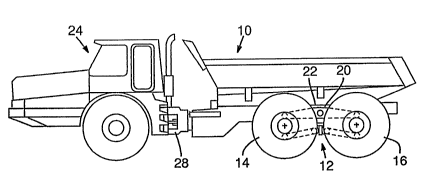
Figure 1 shows a dump vehicle 10 having a rear
suspension apparatus 12 mounted on each side of the
vehicle. The suspension apparatus 12 includes a front
wheel 14 and a rear wheel 16, each of which is carried
by an assembly that is pivotally attached to an opposite
end of a walking beam or equalizer beam 20. The
equalizer beam 20 is pivotally attached to the vehicle
frame 22 at the beam's midpoint. Accordingly, the front
wheel 14 rises while the rear wheel 16 descends
correspondingly, and vice versa. This accommodates and
~::
_3_ 21'L3209
"averages out" bumps and holes in the surface on which
the vehicle is operated.
The dump vehicle lO includes a cab section 24
attached to the vehicle frame 22 by an articulated joint
28 that allows the cab to pivot or yaw laterally with
respect to the frame 22 for steering, and to rotate or
roll with respect to the frame for accommodating terrain
variations. In total, the vehicle 10 has six wheels,
all of which should remain in contact with a roughly
contoured ground surface.
Figure 3 shows a detailed view of the
suspension apparatus 12 as installed on the left side of
the vehicle. A trunnion block 30 is attached to the
frame and defines a semi-circular recess 32. A
cylindrical trunnion 34 is secured in the recess by a
trunnion cap 36 bolted to the trunnion block 30.
Accordingly, the trunnion 34 provides a suspension pivot
connection having a horizontal central pivot axi~ 40
perpendicular to the longitudinal axis of the vehicle.
The equalizer beam 20 is a rigid elongated
member defining a bore 42 at its mid-point. The bore 42
alosely receives the trunnion 34 so that the beam 20 may
pivot freely about the suspen6ion pivot central axis 40.
The beam 20 has a first end 44 including a first pivot
pin 48 protruding horizontally therefrom. The first
pivot pin 48 is centered on a first end pivot axis 50.
Similarly, the beam 20 has an opposite second end 54
including a protruding second pivot pin 58 centered on a -
second end pivot axis 60. In the preferred embodiment,
the beam 20 is generally straight, with the pivot axes
40, 50, and 60 residing in a common plane. However,
di~ferent applications may dictate that the beam be
angled so that the axes are not positioned within the
same plane.
The vehicle 10 has a drive train 62 including a
first differential housing 64 positioned generally
I between the front wheels 14 and a second differential
housing 66 positioned generally between the rear wheels
_4_ 2113209
16. A pair of first axle housings 70 protrude laterally
from opposite sides of the first differential housing
64. A first axle 72 is received within the housing 70,
and is connected to a differential gear (not shown)
S contained within the housing 64 so that the axle 72 is
driven to rotate on a first wheel axis 74. The distal
end of the axle 72 is connected to wheel 1~ to drive the
wheel, which rotates on the first wheel axis 74.
Similarly, the second differential housing
includes a pair of second axle housings 78 containing a
second axle 80 rotating on a second wheel axis 82 to
drive wheel 16.
The suspension apparatus provided on the right
side of the vehicle operates independently of that shown
on the left, although transverse torque rods (not shown)
may link each beam 20 to a respective differential
housing 64, 66 to resist excessive pivoting in opposite
directions.
A pair of first support plates 86 is rigidly
attached at their lower ends to the first axle housing
70 and are spaced apart to receive the first beam end 44
therebetween. The plates 86 are pivotally attached at
their upper ends to the beam first end, defining bores
for receiving the first pivot pin 48.
Similarly, a pair of second support plates 88
is rigidly attached to the second axle housing 78 and
pivotally attached to the second beam end 54 in the same
manner.
Consequently, the end pivot axes 50, 60 of the
beam 20 are positioned vertically above the respective
wheel axes 74, 80. The beam ends need not be laterally
aligned with the wheel axes, but are positioned within
horizontal planes at a level above the corresponding
portions of the wheel axes.
A first torque rod attachment bracket 90
depends below a distal end of the first axle housing 70
and is rigidly attached thereto. The bracket 90
includes a first attachment pin 92 centered on a
~,
.. . .. .
.. , ~: , - -
~$: ` .:` : . . : ~
-5- 21132~9
horizontal axis 94 oriented parallel to and positioned
generally below the first wheel axis 74. Similarly, a
second torque rod attachment bracket 98 having a second
attachment pin 100 centered on axis 102 is attached
below the second axle housing 78. Together, plates 86,
axle housing 70, bracket 90, and pin 92 comprise a first
wheel axle assembly. Likewise, plates 88, axle housing
78, bracket 98, and pin 100 comprise a second wheel axle
assembly.
A torque rod frame bracket 106 is rigidly
attached to the frame 22, and depends downwardly
therefrom, aligned with the suspension pivot axis 40.
The bracket 106 includes a front bracket attachment pin
108 and a rear bracket attachment pin 110, each centered
on a respective horizontal axis 112, 114. Axes 112 and
114 are positioned in a common horizontal plane above
axes 94 and 102.
A pair of torque rods 118 and 126 connect the
wheel assemblies to the frame bracket 106. The first
elongated torque rod 118 has a front end 120 pivotally
attached to the first attachment pin 92 and a rear end
122 pivotally attached to the front bracket attachment
pin 108. Likewise, the second torque rod 126 has a
front end 128 pivotally attached to the rear bracket
attachment pin 110, and a rear end 130 pivotally
attached to the second attachment pin 100.
The tor~ue rods 118, 126 provide horizontal
positioning of the wheels and proportionally resist
excessive flexure of the suspension. The torque rods
need only withstand axial and torsional stresses, and do
not support ~he weight of the vehicle. Therefore, the
rod ends may be relatively slim, unlike the equalizer
beam 20, which supports a substantial load.
Each rod end 120, 130 is positioned at a level
only slightly below the respeckive axle housing, thereby
slightly limiting ground clearance of the vehicle. As
shown in Fig. 3, the rod ends 120, 130 do not extend
``` 2113209
appreciably below the lowest points of the differential
housings 64, 66.
In the preferred embodiment, the lowest points on
the differential housings are 25 inches above the ground.
The lowest points on the suspension (torque rod ends 120,
130) are ~4 inches above ground, and widely spaced apart by
about 4 feet to permit some obstacles to pass therebetween.
Having illustrated and described the principles
of the invention by what is presently a preferred embodi- -
ment, it should be apparent to those persons skilled in the
art that the illustrated embodiment may be modified without
departing from such principles. The claimed invention
includes not only the illustrated embodiment, but all such
modifications, variations and equivalents thereof as fall
within the true spirit and scope of the following claims.
,
.'!.~.. . '