Language selection

Search

Patent 2113235 Summary

Third-party information liability

Some of the information on this Web page has been provided by external sources. The Government of Canada is not responsible for the accuracy, reliability or currency of the information supplied by external sources. Users wishing to rely upon this information should consult directly with the source of the information. Content provided by external sources is not subject to official languages, privacy and accessibility requirements.

Claims and Abstract availability

Any discrepancies in the text and image of the Claims and Abstract are due to differing posting times. Text of the Claims and Abstract are posted:

  • At the time the application is open to public inspection;
  • At the time of issue of the patent (grant).
(12) Patent Application: (11) CA 2113235
(54) English Title: CALVING PANEL
(54) French Title: DISPOSITIF POUR MISE BAS
Status: Deemed Abandoned and Beyond the Period of Reinstatement - Pending Response to Notice of Disregarded Communication
Bibliographic Data
Abstracts

English Abstract


A device for capturing and restraining a cow for the
purpose of examination and/or assisting with the delivery
and subsequent suckling of a calf and/or performing such
medical procedures as may be required is constructed of
steel and comprises a headgate, a side panel and a
detachable back gate. The headgate has sleeves that attach
with pins to mounting plates or a maternity pen on the right
side and is welded at a right angle on the left side to the
side panel. The top section of the side panel comprises
removable vertical bars to facilitate access to perform a
cesarean section. At the lower rear of the side panel is a
section which can be removed to permit access to the cow's
udder for a calf to suckle. Removal of this section also
allows greater access for a calf puller if necessary.
Attached to sleeves on the back of the side panel is a
detachable back gate which pivots to be closed and fastened
behind the cow or lifts upwards to be removed entirely to
provide access to the rear of the cow.


Claims

Note: Claims are shown in the official language in which they were submitted.

THE EMBODIMENTS OF THE INVENTION IN WHICH AN EXCLUSIVE
PROPERTY OR PRIVILEGE IS CLAIMED ARE DEFINED AS FOLLOWS:
1. A device for capturing and restraining a cow for the
purpose of examination and/or assisting with the delivery
and subsequent suckling of a calf and/or performing such
medical procedures as may be required which is constructed
of steel and comprises:
a headgate,
a side panel, and
a detachable back gate.
2. A device as claimed in claim 1 wherein the headgate
comprises:
a frame,
two vertical uprights, and
a latch.
3. A device as claimed in claim 2 wherein one vertical
upright is fixed at the top and bottom; the second vertical
upright is inserted into one of several holes in the top of
the bottom section of the frame, the top of the second
vertical upright being allowed to slide from side to side in
a horizontal slot in the top section of the frame; and the
latch locks the second vertical upright at specific
locations along the top section of the frame.
4. A device as claimed in claim 2 comprising a vertical
notch in the bottom of the top section of the frame located
near the end of travel of the second vertical upright which
allows the second vertical upright to be manually slid along

the horizontal slot to the vertical notch, lifted upwards,
and moved to a different hole at the bottom for adjustment
or moved out of the way to free the cow.
5. A device as claimed in claim 2 where in sleeves are
affixed to the right side of the headgate frame near the top
and the bottom.
6. A device as claimed in claim 5 wherein the sleeves on
the frame are connected to mounting plates or maternity pen
mounts by aligning the sleeves on the frame with the sleeves
on the mounts and inserting pins.
7. A device as claimed in claim 1 wherein the side panel
comprises:
a frame,
multiple removable vertical bars,
a removable nursing section,
a chain, and
a latch
8. A device as claimed in claim 1 wherein the front of the
frame of the side panel is welded to the left side of the
frame of the headgate at a right angle.
9. A device as claimed in claim 7 wherein the multiple
removable vertical bars are located in the upper section of
the side panel.
10. A device as claimed in claim 7 or 9 wherein the
multiple removable vertical bars are positioned in holes
located in the frame in such a way that each removable bar
may be manually raised upward and removed.

11. A device as claimed in claim 7 wherein the removable
nursing section is located at the lower rear of the side
panel.
12. A device as claimed in claim 11 wherein the removable
nursing section is secured to the frame of the side panel by
a pin.
13. A device as claimed in claim 7 wherein the chain is
attached to the rear of the frame of the side panel.
14. A device as claimed in claim 7 wherein the latch is
fixed to the rear of the frame of the side panel.
15. A device as claimed in claim 7 and 14 wherein the latch
has a cut-out notch for insertion of a chain link in order
to secure the chain at any given location.
16. A device as claimed in claim 7 wherein sleeves are
affixed to the rear of the side panel frame near the top and
the bottom.
17. A device as claimed in claim 7 wherein rods are welded
to the left side of the detachable back gate near the top
and the bottom.
18. A device as claimed in claim 7 wherein the detachable
back gate is attached to the side panel by inserting the
bottoms of the rods on the detachable back gate into the
tops of the sleeves on the rear of the side panel frame.
19. A device as claimed in claim 1, 16, 17, or 18 whereby
the detachable back gate pivots in the hinge system formed

by inserting the rods on the detachable back gate into the
sleeves on the rear of the side panel.
20. A device as claimed in claim 1, 5 or 6 whereby the
entire device pivots on the hinge system created by
connecting the sleeves on the headgate frame to the sleeves
on the mounting plates or the maternity pen mounts with
pins, allowing the entire device to be swung out of the way
when not in use.
21. A calving panel, constructed of steel, comprising:
a headgate with a frame having two vertical uprights,
the first one fixed to the frame at the top and the bottom,
the second inserted into one of several holes in the top of
the bottom section of the frame and allowed to slide from side
to side at the top in a horizontal slot at the top of the
frame and further able to latch at specific locations on the
top of the frame, in order to capture and restrain a cow,
the frame having a vertical notch on the bottom of the top
section for removal and/or adjustment of the second vertical
upright;
a side panel having a frame connected at a right angle
to the left side of the headgate frame, the side panel also
having multiple removable vertical bars in the upper
section, with each vertical bar removable for performing
cesarean sections as well as a lower rear nursing section
secured to the frame by a pin and removable to provide
access to the rear of the cow for a suckling calf or a calf
puller, and a chain and a notched latch for further
restraining the cow; and

a detachable back gate which can be mounted to the back
of the side panel frame by way of attached rods and sleeves
to assist in the capture of the cow, swung to close behind
the cow, or lifted off to provide greater access to the rear
of the cow to assist with calving;
the entire calving panel having the ability to be mounted to
a wall or maternity pen by use of sleeves and pins located
on the right of the headgate frame and also having the
ability to pivot for easier capture of the cow or to be
swung out of the way when not in use.

Description

Note: Descriptions are shown in the official language in which they were submitted.


2113235
CALVING P~NEL
The present invention relates to a device to promote
the safe handling of a cow for a variety of procedures,
specifically to assist in delivery and suckling of a calf.
The types of devices available for the purpose of
examining a cow and assisting in delivery are contained
within a maternity pen as a fixed stall. As this stall is
permanently located within the maternity pen, it limits the
remaining space in the maternity pen. Some difficulty may
also arise in maneuvering an unwilliny cow into one specific
stall. Not all livestock facilities provide for the space
required to set up a complete maternity pen.
It is desirable to have a device such as a calving
panel which is more easily operable by one person, in that
it allows a cow to be rounded up from within a larger area.
It is further desirable for such a device to take up less
space and to be more portable. The present invention
relates to a device for more easily restraining and
examining and/or assisting a cow in a limited space. This
device may be mounted in a building or maternity pen and may
be transferred from one location to another by removing and
replacing two pins.
The present invention consists of a headgate, a side
panel and a removable bacX gate. In one aspect the device
comprises a headgate consisting of a frame, two vertical
uprights and a latch. The headgate has sleeves that attach
with pins to mounting plate~ or a maternity pen on the right
side.
-- 1 --

` 2~1323~
In another aspect, the headgate is welded at a right
~ angle on the left side to a side panel with removable
vertical bars which are spaced to facilitate access to
perform a cesarean section. In this aspect the side panel
also comprises, at the lower rear, a section which is
secured to the frame by a pin. This pin is easily removed
to allow the section to be removed to permit access to a
cow's udder for a calf to suckle. Removal of this lower
rear section also allows greater access to the rear of the
cow and provides more maneuverability for a calf puller if
necessary.
In a further embodiment of the invention, at the back
of the side panel is a detachable back gate which pivots in
sleeves to be closed and fastened behind the cow or which
can be lifted upwards and removed entirely to provide access
to the rear of the cow.
The invention, as exemplified by a preferred
embodiment, is described with reference to the drawings in
which:
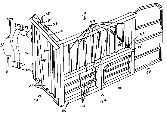
Figure 1 is a perspective view of an embodiment of a
calving panel of the invention; and
Figure 2 is an exploded view of the calving panel shown
in Figure 1.
Referring to the drawings, the embodiment of the
invention shown, a calving panel 10 comprises a headgate
12. The headgate comprises a frame 14, two vertical
uprights 16, 18 and a latch 20. One vertical upright 16 is
fixed at the top and bottom; the second vertical upright 18
i8 inserted into one of several holes 22 in the 'op of the
bottom section of the frame, the top of the second vertical

211~2~5
upright being allowed to slide from side to side in a
~ horizontal slot 24 in the top section of the frame. The
latch locks the second vertical upright at specific
locations 26 along the top section of the frame when pulled
by a rope attached above the latch 28. The headgate also
has a vertical notch 30 in the bottom of the top section of
the frame located near the end of travel of the second
vertical upright which allows the second vertical upright to
be manually slid along the horizontal slot to the vertical
notch, lifted upward, and moved to a different hole at the
bottom for adjustment or moved out of the way to free the
cow. Sleeves 32 are affixed to the right side of the
headgate frame near the top and bottom. The calving panel
is mounted to a wall or maternity pen by aligning these
sleeves with sleeves 34 on the mounting plates 36 and
inserting pins 38 thus creating a pivoting hinge system.
The left side of the headgate frame is welded to the
front of the frame 40 of the side panel 42 at a right
angle. The side panel also comprises multiple removable
vertical bars 44, a removable nursing section 46, a chain 48
and a notched latch 50. The multiple removable vertical bars are
positioned in holes 52 located in the frame in such a way
that each removable vertical bar may be manually raised
upward and removed for casarean sections. The nursing
section may be removed by removing a hairpin 54 and a pin 56
to provide access to the cow's udder for a nursing calf,
- hand milking or a calf puller. A chain and a notched
latch are fixed to the rear of the frame of the side
panel to secure the back of the calving panel once the cow
has been captured.
The back gate 58 is attached to the back of the side

r- - .
~- 211323~
panel by inserting the bottoms of the rods 60 on the gate
into the tops of the sleeves 62 on the rear of the side
panel frame.
A feature of this invention is that the entire unit
pivots on a hinge system affixed to the right side of the
headgate allowing it to swing out when capturing the cow,
and to swing into a 90 degree corner of a building or
maternity pen when not in use. This device can be operated
by one person as it pivots on this hinge system to close in
around a cow simultaneously as the headgàte is latched by a
rope.

Representative Drawing
A single figure which represents the drawing illustrating the invention.
Administrative Status

2024-08-01:As part of the Next Generation Patents (NGP) transition, the Canadian Patents Database (CPD) now contains a more detailed Event History, which replicates the Event Log of our new back-office solution.

Please note that "Inactive:" events refers to events no longer in use in our new back-office solution.

For a clearer understanding of the status of the application/patent presented on this page, the site Disclaimer , as well as the definitions for Patent , Event History , Maintenance Fee  and Payment History  should be consulted.

Event History

Description Date
Time Limit for Reversal Expired 2002-01-11
Application Not Reinstated by Deadline 2002-01-11
Deemed Abandoned - Failure to Respond to Maintenance Fee Notice 2001-01-11
Inactive: Abandon-RFE+Late fee unpaid-Correspondence sent 2001-01-11
Application Published (Open to Public Inspection) 1995-07-12

Abandonment History

Abandonment Date Reason Reinstatement Date
2001-01-11

Maintenance Fee

The last payment was received on 1999-12-30

Note : If the full payment has not been received on or before the date indicated, a further fee may be required which may be one of the following

  • the reinstatement fee;
  • the late payment fee; or
  • additional fee to reverse deemed expiry.

Please refer to the CIPO Patent Fees web page to see all current fee amounts.

Fee History

Fee Type Anniversary Year Due Date Paid Date
MF (application, 4th anniv.) - small 04 1998-01-20 1997-12-22
MF (application, 5th anniv.) - small 05 1999-01-11 1999-01-06
MF (application, 6th anniv.) - small 06 2000-01-11 1999-12-30
Owners on Record

Note: Records showing the ownership history in alphabetical order.

Current Owners on Record
GARY KOCHANOWSKI
CINDY KOCHANOWSKI
Past Owners on Record
None
Past Owners that do not appear in the "Owners on Record" listing will appear in other documentation within the application.
Documents

To view selected files, please enter reCAPTCHA code :


To view images, click a link in the Document Description column. To download the documents, select one or more checkboxes in the first column and then click the "Download Selected in PDF format (Zip Archive)" or the "Download Selected as Single PDF" button.

List of published and non-published patent-specific documents on the CPD .

If you have any difficulty accessing content, you can call the Client Service Centre at 1-866-997-1936 or send them an e-mail at CIPO Client Service Centre.


Document
Description 
Date
(yyyy-mm-dd) 
Number of pages   Size of Image (KB) 
Abstract 1995-07-12 1 26
Cover Page 1995-09-01 1 15
Description 1995-07-12 4 120
Claims 1995-07-12 5 129
Drawings 1995-07-12 2 62
Representative drawing 1998-05-15 1 33
Notice: Maintenance Fee Reminder 1997-10-16 1 119
Notice: Maintenance Fee Reminder 1998-10-14 1 118
Notice: Maintenance Fee Reminder 1999-10-13 1 119
Reminder - Request for Examination 2000-09-12 1 116
Notice: Maintenance Fee Reminder 2000-10-12 1 119
Courtesy - Abandonment Letter (Maintenance Fee) 2001-02-08 1 182
Courtesy - Abandonment Letter (Request for Examination) 2001-02-22 1 169
Second Notice: Maintenance Fee Reminder 2001-07-12 1 119
Notice: Maintenance Fee Reminder 2001-10-15 1 131
Fees 1999-12-30 2 106
Fees 1999-01-06 1 63
Fees 1997-12-22 1 91
Fees 1996-12-12 1 49
Fees 1996-01-03 2 69