Language selection

Search

Patent 2113289 Summary

Third-party information liability

Some of the information on this Web page has been provided by external sources. The Government of Canada is not responsible for the accuracy, reliability or currency of the information supplied by external sources. Users wishing to rely upon this information should consult directly with the source of the information. Content provided by external sources is not subject to official languages, privacy and accessibility requirements.

Claims and Abstract availability

Any discrepancies in the text and image of the Claims and Abstract are due to differing posting times. Text of the Claims and Abstract are posted:

  • At the time the application is open to public inspection;
  • At the time of issue of the patent (grant).
(12) Patent: (11) CA 2113289
(54) English Title: TRANSMISSION SHUTTLE SHIFT DECELERATION METHOD
(54) French Title: METHODE DE DECELERATION POUR TRANSMISSION A INVERSEUR DE MARCHE
Status: Expired and beyond the Period of Reversal
Bibliographic Data
(51) International Patent Classification (IPC):
  • F16H 63/02 (2006.01)
  • F16H 59/08 (2006.01)
  • F16H 61/02 (2006.01)
  • F16H 61/684 (2006.01)
  • F16H 61/70 (2006.01)
(72) Inventors :
  • VAUGHTERS, KEVIN LEE (United States of America)
(73) Owners :
  • DEERE & COMPANY
(71) Applicants :
  • DEERE & COMPANY (United States of America)
(74) Agent: BORDEN LADNER GERVAIS LLP
(74) Associate agent:
(45) Issued: 1997-12-16
(22) Filed Date: 1994-01-13
(41) Open to Public Inspection: 1994-07-30
Examination requested: 1994-01-13
Availability of licence: N/A
Dedicated to the Public: N/A
(25) Language of filing: English

Patent Cooperation Treaty (PCT): No

(30) Application Priority Data:
Application No. Country/Territory Date
010,942 (United States of America) 1993-01-29

Abstracts

English Abstract


A powershift transmission includes a plurality of
clutches, including a final or directional set of clutches.
The clutches are controlled by electro-hydraulic direct acting
valves and two electro-hydraulic proportional or pressure
modulating valves. The pressure modulating valves modulate
the pressure supplied to the direct acting valves associated
with the three directional clutches. Vehicle deceleration
during a shuttle shift is achieved by releasing
(unpressurizing) all clutches, then gradually pressurizing
only two clutches in the final or directional set.


French Abstract

Transmission automatique comportant plusieurs embrayages, dont un ensemble d'embrayages finals ou directionnels. Les embrayages sont commandés par des électrovalves hydrauliques à action directe et par deux électrovalves hydrauliques proportionnelles ou régulatrices de pression. Les valves modulatrices de pression règlent la pression fournie aux valves à action directe associées aux trois embrayages de marche. La décélération du véhicule pendant un changement de vitesse est effectuée par débrayage (dépressurisation) et par augmentation graduelle de la pression sur seulement deux embrayages dans l'ensemble des embrayages finals ou directionnels.

Claims

Note: Claims are shown in the official language in which they were submitted.

THE EMBODIMENTS OF THE INVENTION IN WHICH AN EXCLUSIVE
PROPERTY OR PRIVILEGE IS CLAIMED ARE DEFINED AS FOLLOWS:
1. A method of decelerating an output shaft of a vehicle
powershift transmission during a shuttle shift whereby
rotation of the output shaft is reversed from a first
direction to a second direction, the transmission having a
plurality of hydraulic pressure operated clutch elements for
shifting the transmission, including a set of directional
clutches, the method comprising the following steps:
disengaging all the clutch elements, including all the
directional clutches;
applying pressurized fluid to only to both a first
directional clutch and to a second directional clutch to lock
up the transmission;
when the output shaft speed approaches zero, applying
pressurized fluid to at least one selected clutch other than a
directional clutch to engage a desired gear and to cause the
output shaft to rotate in the second direction; and
releasing pressure from at least the first directional
clutch.
2. The method of claim 1, wherein:
the pressure applied to the first and second directional
clutches is gradually increased to gradually decelerate the
output shaft.
3. The method of claim 1, further comprising:
gradually increasing the pressure applied to a
directional clutch to gradually accelerate the output shaft in
the second direction.

Description

Note: Descriptions are shown in the official language in which they were submitted.


-- 21~328~
TRANSMISSION SHUTTLE SHIFT DECELERATION METHOD
Background of the Invention
This invention relates to a vehicle transmission control
system, in particular a method for shuttle shifting a
powershift transmission having solenoid valve operated
transmission control elements, such as brakes and clutches.
Power shift transmissions are known in the art. A
control system for a known powershift transmission such as a
Funk 8000 Series powershift transmission is described in US
Patent No. 4,989,470, issued 5 February 1991 to Bulgrien.
This powershiEt transmission includes an initial set of three
clutches, an intermediate set of three clutches and a final or
directional set of three clutches. The clutches are
controlled by nine electro-hydraulic 3-way, 2-position direct
acting valves and two electro-hydraulic proportional or
pressure modulating valves. The pressure modulating valves
modulate the pressure supplied to the direct acting valves
associated with the three directional clutches. Such
powershift transmissions may be controlled to provide a
shuttle shift capability which permits the vehicle to slow
down and then change direction of operation without requiring
the movement of the gearshift lever through each intermediate
gear ratio. One such shuttle shifting method is described in
the above mentioned patent to Bulgrien, wherein all clutches
in an initial set of clutches are released to disconnect the
engine from the drive train, at least two clutches in an
intermediate set of clutches are engaged to lock up the
transmission, at least one clutch in a final set of clutches
is engaged to reduce vehicle speed to zero, then after the
vehicle speed has been reduced to zero, one clutch in each set
is engaged to engage the desired new gear ratio. Thus, this
method requires that a minimum of at least three clutches be
operated merely to decelerate the vehicle during a shuttle
shift. It would be desirable to decelerate the vehicle during
a shuttle shift with fewer clutch operations in order to
increase system reliability.
. . -' ~ , :
,~, . : ,

211328~
Summary of the Invention
An object o~ the invention is to provide a method for
shuttle shifting a powershift transmission which has improved
reliability and which requires manipulation of the least
possible number of clutches and valves.
These and other objects are achieved by the present
invention, wherein a powershift transmission includes a
plurality of clutches, including a final or directional set of
clutches. The clutches are controlled by electro-hydraulic
direct acting valves and two electro-hydraulic proportional or
pressure modulating valves. The pressure modulating valves
modulate the pressure supplied to the direct acting valves
associated with the three directional clutches. Vehicle
deceleration during a shuttle shift is achieved by releasing
(unpressurizing) all clutches, then gradually pressurizing
only two clutches in the final or directional set.
Brief Description of the Drawings
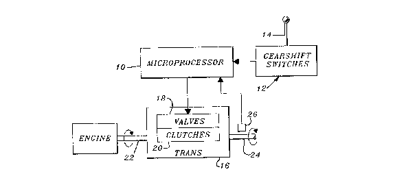
Fig. 1 is a schematic diagram of a powershift
transmission control system to which the present invention is
applicable.
Fig. 2 is a schematic sectional view of a transmission to
which the present invention is applicable.
FIG. 3 is a simplified logic flow diagram of an algorithm
which is performed by the method of the present invention
during a forward-to-reverse shuttle shift.
FIG. 4 is a simplified logic flow diagram of an algorithm
which is performed by the method of the present invention
during a reverse-to-forward shuttle shift.
Detailed Description
Referring to FIG. 1, a power shift transmission control
system includes a microprocessor 10, a gearshift lever
transducer or switch assembly 12 which is operated by manually
moving a gearshift lever 14, and a power shift transmission
16. The power shift transmission 16 is preferably a known
power shift transmission such as the 8000 Series transmission
manufactured by Funk Manufacturing. This known power shift
transmission includes a hydraulic control valve assembly 18
~ J '
.. ' . . .
;", ~- : ' ,' '
.'._' ' ' :
. ". . ~ ~ .
''.'~'" . '
, ' . .' : . .
"~
-'~, , .;

21132~
which controls a plurality of hydraulically operated clutches
20, including directional clutches F1, F2 and R as best seen
in Fig. 2. The transmission transmits power from an engine
driven input shaft 22 to an output or vehicle drive shaft 24.
A sensor 26 senses rotation of shaft 22 to provide output
signals representing vehicle speed.
Preferably, the gearshift lever 14 will have forward,
neutral and reverse positions, may have upshift and downshift
sub-positions associated with the forward and reverse
positions, and may be moved directly from a forward to a
reverse position or from a reverse to a forward position to
acomplish what is known as a "shuttle shift". The
microprocessor 10 periodically samples the position of the
lever 14 controls the operation of the valves 18 and clutches
20 accordingly.
Referring now to FIG. 2, the transmission 16 includes a
final or directional set of clutches including clutches F1, F2
and R. The present invention concerns the method in which
clutches F1, F2 and R are operated to decelerate the vehicle
(not shown) in which the transmission 16 is installed during a
shuttle shift operation.
Referring now to FIG. 3, a shuttle shift from a gear in
the forward range to a gear in ~he reverse range is
accomplished as follows:
First, all the clutches are unlocked (step 100). Then,
sufficient current is applied to the MC2 proportional valve
(which controls the pressure to clutches F2 and R) to drop the
pilot pressure to a pressure just sufficient to cause initi~al
clutch engagement, for example, approximately 50 psig. (step
102). Next, this pilot pressure is applied to the F2 and R
clutches (step 104). Since clutch R possesses a torque
advantage relative to the output, clutch R will lock up and
clutch F2 will slip.
Then, the pressure supplied to clutches F2 and R (by the
MC2 proportional valve) is modulated or increased to achieve a
gradual and controlled deceleration of the tractor. For
example, a feed-back loop might be used to adjust the pressure
.. ,- : ,
., . , . , , - - ... .
.,
,,
"",~ .,

applied to clutches F2 and R as a function of the rate of
deceleration as indicated by a transmission output speed
sensor (steps 106 and 108). As a result the F2 clutch, alone,
will absorb energy and begin to decelerate the tractor.
Once the tractor has come to rest, or to a predetermined
grond speed, one or more clutches would be applied to place
the transmission in the desired gear for movement in the
opposite direction (step 110), and pressure is released from
the F2 clutch (step 112) while pressure is maintained in
clutch R.
Next, the pressure supplied to clutch R (by the MC2
proportional valve) is modulated or increa~ed to achieve a
gradual and controlled acceleration of the tractor in the new
direction (step 114). Again, a feed-back loop might be used
to control the acceleration rate of the tractor.
Referring now to FIG. 4, a shuttle shift from a gear in
the reverse range to a gear in the forward (low) range is
accomplished as follows:
First, all the clutches are unlocked (step 120). Then,
sufficient current is applied to the MC2 proportional valve
(which controls the pressure to clutches F2 and R) to drop the
pilot pressure to a pressure just sufficient to cause initial
clutch engagement, for example, approximately 50 psig (step
122). Next, this pilot pressure is applied to the F2 and R
clutches (step 124). Since clutch R possesses a torque
advantage relative to the output, clutch R will lock up and
clutch F2 will slip.
Then, the pressure supplied to clutches F2 and R (by the
MC2 proportional valve) is modulated or increased to achieve a
gradual and controlled deceleration of the tractor. For
example, a feed back loop might be used to adjust the pressure
applied to clutches F2 and R as a function of the rate of
deceleration as indicated by a transmission output speed
sensor (steps 126 and 128). As a result the F2 clutch, alone,
will absorb energy and begin to decelerate the tractor. Also,
- due to different clutch slip speeds, the pressure rise rate
i
, .
~ .
'~'," ~. :
~" '
. ,,. !:,.. .
.:',i. :;'':,
: '~' :,' ;' ' . :
~ :~'r~

211328~
may be different for a reverse-to-forward shuttle shift as
compared to a forward-to-reverse shuttle shift.
Once the tractor has come to rest, or a predetermined
ground speed, modulation valve MCl is controlled to pressurize
clutch F1 with a pilot pressure just sufficient to cause
initial clutch engagement, for example, approximately 50 psig
(step 130). Then, one or more clutches would be applied to
place the transmission in the desired gear for movement in the
opposite direction (step 132), and pressure is released from
the F2 and R clutches and current to the MC2 proportional
valve is shut off (steps 134 and 136).
Next, the pressure supplied to clutch F1 (by the MC1
proportional valve) is modulated or increased to achieve a
gradual and controlled acceleration of the tractor in the new
direction (step 138). Again, a feed-back loop might be used
to control the acceleration rate of the tractor.
While the present invention has been described in
conjunction with a specific embodiment, it is understood that
many alternatives, modifications and variations will be
apparent to those skilled in the art in light of the foregoing
description. Accordingly, this invention is intended to
embrace all such alternatives, modifications and variations
which fall within the spirit and scope of the appended claims.
. .
. .
" .
~".. : '
.,' :;',
; :'':
..;; , ~:
'', ' ~ ' . ,
~A ~

Representative Drawing
A single figure which represents the drawing illustrating the invention.
Administrative Status

2024-08-01:As part of the Next Generation Patents (NGP) transition, the Canadian Patents Database (CPD) now contains a more detailed Event History, which replicates the Event Log of our new back-office solution.

Please note that "Inactive:" events refers to events no longer in use in our new back-office solution.

For a clearer understanding of the status of the application/patent presented on this page, the site Disclaimer , as well as the definitions for Patent , Event History , Maintenance Fee  and Payment History  should be consulted.

Event History

Description Date
Time Limit for Reversal Expired 2010-01-13
Letter Sent 2009-01-13
Inactive: IPC from MCD 2006-03-11
Letter Sent 2004-02-06
Grant by Issuance 1997-12-16
Inactive: Application prosecuted on TS as of Log entry date 1997-10-09
Inactive: Status info is complete as of Log entry date 1997-10-09
Pre-grant 1997-07-22
Notice of Allowance is Issued 1997-02-18
Application Published (Open to Public Inspection) 1994-07-30
All Requirements for Examination Determined Compliant 1994-01-13
Request for Examination Requirements Determined Compliant 1994-01-13

Abandonment History

There is no abandonment history.

Fee History

Fee Type Anniversary Year Due Date Paid Date
Final fee - standard 1997-07-22
MF (patent, 4th anniv.) - standard 1998-01-20 1998-01-12
MF (patent, 5th anniv.) - standard 1999-01-13 1999-01-12
MF (patent, 6th anniv.) - standard 2000-01-13 2000-01-12
MF (patent, 7th anniv.) - standard 2001-01-15 2001-01-12
MF (patent, 8th anniv.) - standard 2002-01-14 2002-01-11
MF (patent, 9th anniv.) - standard 2003-01-13 2003-01-10
MF (patent, 10th anniv.) - standard 2004-01-13 2003-12-22
MF (patent, 11th anniv.) - standard 2005-01-13 2004-12-21
MF (patent, 12th anniv.) - standard 2006-01-13 2005-12-30
MF (patent, 13th anniv.) - standard 2007-01-15 2006-12-20
MF (patent, 14th anniv.) - standard 2008-01-14 2007-12-18
Owners on Record

Note: Records showing the ownership history in alphabetical order.

Current Owners on Record
DEERE & COMPANY
Past Owners on Record
KEVIN LEE VAUGHTERS
Past Owners that do not appear in the "Owners on Record" listing will appear in other documentation within the application.
Documents

To view selected files, please enter reCAPTCHA code :


To view images, click a link in the Document Description column. To download the documents, select one or more checkboxes in the first column and then click the "Download Selected in PDF format (Zip Archive)" or the "Download Selected as Single PDF" button.

List of published and non-published patent-specific documents on the CPD .

If you have any difficulty accessing content, you can call the Client Service Centre at 1-866-997-1936 or send them an e-mail at CIPO Client Service Centre.


Document
Description 
Date
(yyyy-mm-dd) 
Number of pages   Size of Image (KB) 
Claims 1997-02-17 1 36
Abstract 1995-04-07 1 21
Claims 1995-04-07 1 34
Drawings 1995-04-07 4 150
Description 1995-04-07 5 232
Representative drawing 1997-12-10 1 6
Maintenance Fee Notice 2009-02-23 1 171
Correspondence 2004-02-05 1 17
Fees 1997-01-09 1 56
Fees 1996-01-11 1 46
Prosecution correspondence 1994-05-26 2 33
PCT Correspondence 1997-07-21 1 35