Sélection de la langue

Search

Sommaire du brevet 2113289 

Énoncé de désistement de responsabilité concernant l'information provenant de tiers

Une partie des informations de ce site Web a été fournie par des sources externes. Le gouvernement du Canada n'assume aucune responsabilité concernant la précision, l'actualité ou la fiabilité des informations fournies par les sources externes. Les utilisateurs qui désirent employer cette information devraient consulter directement la source des informations. Le contenu fourni par les sources externes n'est pas assujetti aux exigences sur les langues officielles, la protection des renseignements personnels et l'accessibilité.

Disponibilité de l'Abrégé et des Revendications

L'apparition de différences dans le texte et l'image des Revendications et de l'Abrégé dépend du moment auquel le document est publié. Les textes des Revendications et de l'Abrégé sont affichés :

  • lorsque la demande peut être examinée par le public;
  • lorsque le brevet est émis (délivrance).
(12) Brevet: (11) CA 2113289
(54) Titre français: METHODE DE DECELERATION POUR TRANSMISSION A INVERSEUR DE MARCHE
(54) Titre anglais: TRANSMISSION SHUTTLE SHIFT DECELERATION METHOD
Statut: Périmé et au-delà du délai pour l’annulation
Données bibliographiques
(51) Classification internationale des brevets (CIB):
  • F16H 63/02 (2006.01)
  • F16H 59/08 (2006.01)
  • F16H 61/02 (2006.01)
  • F16H 61/684 (2006.01)
  • F16H 61/70 (2006.01)
(72) Inventeurs :
  • VAUGHTERS, KEVIN LEE (Etats-Unis d'Amérique)
(73) Titulaires :
  • DEERE & COMPANY
(71) Demandeurs :
  • DEERE & COMPANY (Etats-Unis d'Amérique)
(74) Agent: BORDEN LADNER GERVAIS LLP
(74) Co-agent:
(45) Délivré: 1997-12-16
(22) Date de dépôt: 1994-01-13
(41) Mise à la disponibilité du public: 1994-07-30
Requête d'examen: 1994-01-13
Licence disponible: S.O.
Cédé au domaine public: S.O.
(25) Langue des documents déposés: Anglais

Traité de coopération en matière de brevets (PCT): Non

(30) Données de priorité de la demande:
Numéro de la demande Pays / territoire Date
010,942 (Etats-Unis d'Amérique) 1993-01-29

Abrégés

Abrégé français

Transmission automatique comportant plusieurs embrayages, dont un ensemble d'embrayages finals ou directionnels. Les embrayages sont commandés par des électrovalves hydrauliques à action directe et par deux électrovalves hydrauliques proportionnelles ou régulatrices de pression. Les valves modulatrices de pression règlent la pression fournie aux valves à action directe associées aux trois embrayages de marche. La décélération du véhicule pendant un changement de vitesse est effectuée par débrayage (dépressurisation) et par augmentation graduelle de la pression sur seulement deux embrayages dans l'ensemble des embrayages finals ou directionnels.


Abrégé anglais


A powershift transmission includes a plurality of
clutches, including a final or directional set of clutches.
The clutches are controlled by electro-hydraulic direct acting
valves and two electro-hydraulic proportional or pressure
modulating valves. The pressure modulating valves modulate
the pressure supplied to the direct acting valves associated
with the three directional clutches. Vehicle deceleration
during a shuttle shift is achieved by releasing
(unpressurizing) all clutches, then gradually pressurizing
only two clutches in the final or directional set.

Revendications

Note : Les revendications sont présentées dans la langue officielle dans laquelle elles ont été soumises.


THE EMBODIMENTS OF THE INVENTION IN WHICH AN EXCLUSIVE
PROPERTY OR PRIVILEGE IS CLAIMED ARE DEFINED AS FOLLOWS:
1. A method of decelerating an output shaft of a vehicle
powershift transmission during a shuttle shift whereby
rotation of the output shaft is reversed from a first
direction to a second direction, the transmission having a
plurality of hydraulic pressure operated clutch elements for
shifting the transmission, including a set of directional
clutches, the method comprising the following steps:
disengaging all the clutch elements, including all the
directional clutches;
applying pressurized fluid to only to both a first
directional clutch and to a second directional clutch to lock
up the transmission;
when the output shaft speed approaches zero, applying
pressurized fluid to at least one selected clutch other than a
directional clutch to engage a desired gear and to cause the
output shaft to rotate in the second direction; and
releasing pressure from at least the first directional
clutch.
2. The method of claim 1, wherein:
the pressure applied to the first and second directional
clutches is gradually increased to gradually decelerate the
output shaft.
3. The method of claim 1, further comprising:
gradually increasing the pressure applied to a
directional clutch to gradually accelerate the output shaft in
the second direction.

Description

Note : Les descriptions sont présentées dans la langue officielle dans laquelle elles ont été soumises.

-- 21~328~
TRANSMISSION SHUTTLE SHIFT DECELERATION METHOD
Background of the Invention
This invention relates to a vehicle transmission control
system, in particular a method for shuttle shifting a
powershift transmission having solenoid valve operated
transmission control elements, such as brakes and clutches.
Power shift transmissions are known in the art. A
control system for a known powershift transmission such as a
Funk 8000 Series powershift transmission is described in US
Patent No. 4,989,470, issued 5 February 1991 to Bulgrien.
This powershiEt transmission includes an initial set of three
clutches, an intermediate set of three clutches and a final or
directional set of three clutches. The clutches are
controlled by nine electro-hydraulic 3-way, 2-position direct
acting valves and two electro-hydraulic proportional or
pressure modulating valves. The pressure modulating valves
modulate the pressure supplied to the direct acting valves
associated with the three directional clutches. Such
powershift transmissions may be controlled to provide a
shuttle shift capability which permits the vehicle to slow
down and then change direction of operation without requiring
the movement of the gearshift lever through each intermediate
gear ratio. One such shuttle shifting method is described in
the above mentioned patent to Bulgrien, wherein all clutches
in an initial set of clutches are released to disconnect the
engine from the drive train, at least two clutches in an
intermediate set of clutches are engaged to lock up the
transmission, at least one clutch in a final set of clutches
is engaged to reduce vehicle speed to zero, then after the
vehicle speed has been reduced to zero, one clutch in each set
is engaged to engage the desired new gear ratio. Thus, this
method requires that a minimum of at least three clutches be
operated merely to decelerate the vehicle during a shuttle
shift. It would be desirable to decelerate the vehicle during
a shuttle shift with fewer clutch operations in order to
increase system reliability.
. . -' ~ , :
,~, . : ,

211328~
Summary of the Invention
An object o~ the invention is to provide a method for
shuttle shifting a powershift transmission which has improved
reliability and which requires manipulation of the least
possible number of clutches and valves.
These and other objects are achieved by the present
invention, wherein a powershift transmission includes a
plurality of clutches, including a final or directional set of
clutches. The clutches are controlled by electro-hydraulic
direct acting valves and two electro-hydraulic proportional or
pressure modulating valves. The pressure modulating valves
modulate the pressure supplied to the direct acting valves
associated with the three directional clutches. Vehicle
deceleration during a shuttle shift is achieved by releasing
(unpressurizing) all clutches, then gradually pressurizing
only two clutches in the final or directional set.
Brief Description of the Drawings
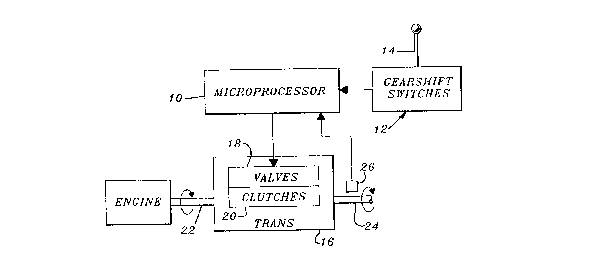
Fig. 1 is a schematic diagram of a powershift
transmission control system to which the present invention is
applicable.
Fig. 2 is a schematic sectional view of a transmission to
which the present invention is applicable.
FIG. 3 is a simplified logic flow diagram of an algorithm
which is performed by the method of the present invention
during a forward-to-reverse shuttle shift.
FIG. 4 is a simplified logic flow diagram of an algorithm
which is performed by the method of the present invention
during a reverse-to-forward shuttle shift.
Detailed Description
Referring to FIG. 1, a power shift transmission control
system includes a microprocessor 10, a gearshift lever
transducer or switch assembly 12 which is operated by manually
moving a gearshift lever 14, and a power shift transmission
16. The power shift transmission 16 is preferably a known
power shift transmission such as the 8000 Series transmission
manufactured by Funk Manufacturing. This known power shift
transmission includes a hydraulic control valve assembly 18
~ J '
.. ' . . .
;", ~- : ' ,' '
.'._' ' ' :
. ". . ~ ~ .
''.'~'" . '
, ' . .' : . .
"~
-'~, , .;

21132~
which controls a plurality of hydraulically operated clutches
20, including directional clutches F1, F2 and R as best seen
in Fig. 2. The transmission transmits power from an engine
driven input shaft 22 to an output or vehicle drive shaft 24.
A sensor 26 senses rotation of shaft 22 to provide output
signals representing vehicle speed.
Preferably, the gearshift lever 14 will have forward,
neutral and reverse positions, may have upshift and downshift
sub-positions associated with the forward and reverse
positions, and may be moved directly from a forward to a
reverse position or from a reverse to a forward position to
acomplish what is known as a "shuttle shift". The
microprocessor 10 periodically samples the position of the
lever 14 controls the operation of the valves 18 and clutches
20 accordingly.
Referring now to FIG. 2, the transmission 16 includes a
final or directional set of clutches including clutches F1, F2
and R. The present invention concerns the method in which
clutches F1, F2 and R are operated to decelerate the vehicle
(not shown) in which the transmission 16 is installed during a
shuttle shift operation.
Referring now to FIG. 3, a shuttle shift from a gear in
the forward range to a gear in ~he reverse range is
accomplished as follows:
First, all the clutches are unlocked (step 100). Then,
sufficient current is applied to the MC2 proportional valve
(which controls the pressure to clutches F2 and R) to drop the
pilot pressure to a pressure just sufficient to cause initi~al
clutch engagement, for example, approximately 50 psig. (step
102). Next, this pilot pressure is applied to the F2 and R
clutches (step 104). Since clutch R possesses a torque
advantage relative to the output, clutch R will lock up and
clutch F2 will slip.
Then, the pressure supplied to clutches F2 and R (by the
MC2 proportional valve) is modulated or increased to achieve a
gradual and controlled deceleration of the tractor. For
example, a feed-back loop might be used to adjust the pressure
.. ,- : ,
., . , . , , - - ... .
.,
,,
"",~ .,

applied to clutches F2 and R as a function of the rate of
deceleration as indicated by a transmission output speed
sensor (steps 106 and 108). As a result the F2 clutch, alone,
will absorb energy and begin to decelerate the tractor.
Once the tractor has come to rest, or to a predetermined
grond speed, one or more clutches would be applied to place
the transmission in the desired gear for movement in the
opposite direction (step 110), and pressure is released from
the F2 clutch (step 112) while pressure is maintained in
clutch R.
Next, the pressure supplied to clutch R (by the MC2
proportional valve) is modulated or increa~ed to achieve a
gradual and controlled acceleration of the tractor in the new
direction (step 114). Again, a feed-back loop might be used
to control the acceleration rate of the tractor.
Referring now to FIG. 4, a shuttle shift from a gear in
the reverse range to a gear in the forward (low) range is
accomplished as follows:
First, all the clutches are unlocked (step 120). Then,
sufficient current is applied to the MC2 proportional valve
(which controls the pressure to clutches F2 and R) to drop the
pilot pressure to a pressure just sufficient to cause initial
clutch engagement, for example, approximately 50 psig (step
122). Next, this pilot pressure is applied to the F2 and R
clutches (step 124). Since clutch R possesses a torque
advantage relative to the output, clutch R will lock up and
clutch F2 will slip.
Then, the pressure supplied to clutches F2 and R (by the
MC2 proportional valve) is modulated or increased to achieve a
gradual and controlled deceleration of the tractor. For
example, a feed back loop might be used to adjust the pressure
applied to clutches F2 and R as a function of the rate of
deceleration as indicated by a transmission output speed
sensor (steps 126 and 128). As a result the F2 clutch, alone,
will absorb energy and begin to decelerate the tractor. Also,
- due to different clutch slip speeds, the pressure rise rate
i
, .
~ .
'~'," ~. :
~" '
. ,,. !:,.. .
.:',i. :;'':,
: '~' :,' ;' ' . :
~ :~'r~

211328~
may be different for a reverse-to-forward shuttle shift as
compared to a forward-to-reverse shuttle shift.
Once the tractor has come to rest, or a predetermined
ground speed, modulation valve MCl is controlled to pressurize
clutch F1 with a pilot pressure just sufficient to cause
initial clutch engagement, for example, approximately 50 psig
(step 130). Then, one or more clutches would be applied to
place the transmission in the desired gear for movement in the
opposite direction (step 132), and pressure is released from
the F2 and R clutches and current to the MC2 proportional
valve is shut off (steps 134 and 136).
Next, the pressure supplied to clutch F1 (by the MC1
proportional valve) is modulated or increased to achieve a
gradual and controlled acceleration of the tractor in the new
direction (step 138). Again, a feed-back loop might be used
to control the acceleration rate of the tractor.
While the present invention has been described in
conjunction with a specific embodiment, it is understood that
many alternatives, modifications and variations will be
apparent to those skilled in the art in light of the foregoing
description. Accordingly, this invention is intended to
embrace all such alternatives, modifications and variations
which fall within the spirit and scope of the appended claims.
. .
. .
" .
~".. : '
.,' :;',
; :'':
..;; , ~:
'', ' ~ ' . ,
~A ~

Dessin représentatif
Une figure unique qui représente un dessin illustrant l'invention.
États administratifs

2024-08-01 : Dans le cadre de la transition vers les Brevets de nouvelle génération (BNG), la base de données sur les brevets canadiens (BDBC) contient désormais un Historique d'événement plus détaillé, qui reproduit le Journal des événements de notre nouvelle solution interne.

Veuillez noter que les événements débutant par « Inactive : » se réfèrent à des événements qui ne sont plus utilisés dans notre nouvelle solution interne.

Pour une meilleure compréhension de l'état de la demande ou brevet qui figure sur cette page, la rubrique Mise en garde , et les descriptions de Brevet , Historique d'événement , Taxes périodiques et Historique des paiements devraient être consultées.

Historique d'événement

Description Date
Le délai pour l'annulation est expiré 2010-01-13
Lettre envoyée 2009-01-13
Inactive : CIB de MCD 2006-03-11
Lettre envoyée 2004-02-06
Accordé par délivrance 1997-12-16
Inactive : Dem. traitée sur TS dès date d'ent. journal 1997-10-09
Inactive : Renseign. sur l'état - Complets dès date d'ent. journ. 1997-10-09
Préoctroi 1997-07-22
Un avis d'acceptation est envoyé 1997-02-18
Demande publiée (accessible au public) 1994-07-30
Toutes les exigences pour l'examen - jugée conforme 1994-01-13
Exigences pour une requête d'examen - jugée conforme 1994-01-13

Historique d'abandonnement

Il n'y a pas d'historique d'abandonnement

Historique des taxes

Type de taxes Anniversaire Échéance Date payée
Taxe finale - générale 1997-07-22
TM (brevet, 4e anniv.) - générale 1998-01-20 1998-01-12
TM (brevet, 5e anniv.) - générale 1999-01-13 1999-01-12
TM (brevet, 6e anniv.) - générale 2000-01-13 2000-01-12
TM (brevet, 7e anniv.) - générale 2001-01-15 2001-01-12
TM (brevet, 8e anniv.) - générale 2002-01-14 2002-01-11
TM (brevet, 9e anniv.) - générale 2003-01-13 2003-01-10
TM (brevet, 10e anniv.) - générale 2004-01-13 2003-12-22
TM (brevet, 11e anniv.) - générale 2005-01-13 2004-12-21
TM (brevet, 12e anniv.) - générale 2006-01-13 2005-12-30
TM (brevet, 13e anniv.) - générale 2007-01-15 2006-12-20
TM (brevet, 14e anniv.) - générale 2008-01-14 2007-12-18
Titulaires au dossier

Les titulaires actuels et antérieures au dossier sont affichés en ordre alphabétique.

Titulaires actuels au dossier
DEERE & COMPANY
Titulaires antérieures au dossier
KEVIN LEE VAUGHTERS
Les propriétaires antérieurs qui ne figurent pas dans la liste des « Propriétaires au dossier » apparaîtront dans d'autres documents au dossier.
Documents

Pour visionner les fichiers sélectionnés, entrer le code reCAPTCHA :


Pour visualiser une image, cliquer sur un lien dans la colonne description du document. Pour télécharger l'image (les images), cliquer l'une ou plusieurs cases à cocher dans la première colonne et ensuite cliquer sur le bouton "Télécharger sélection en format PDF (archive Zip)" ou le bouton "Télécharger sélection (en un fichier PDF fusionné)".

Liste des documents de brevet publiés et non publiés sur la BDBC .

Si vous avez des difficultés à accéder au contenu, veuillez communiquer avec le Centre de services à la clientèle au 1-866-997-1936, ou envoyer un courriel au Centre de service à la clientèle de l'OPIC.


Description du
Document 
Date
(aaaa-mm-jj) 
Nombre de pages   Taille de l'image (Ko) 
Revendications 1997-02-17 1 36
Abrégé 1995-04-07 1 21
Revendications 1995-04-07 1 34
Dessins 1995-04-07 4 150
Description 1995-04-07 5 232
Dessin représentatif 1997-12-10 1 6
Avis concernant la taxe de maintien 2009-02-23 1 171
Correspondance 2004-02-05 1 17
Taxes 1997-01-09 1 56
Taxes 1996-01-11 1 46
Correspondance de la poursuite 1994-05-26 2 33
Correspondance reliée au PCT 1997-07-21 1 35