Note: Descriptions are shown in the official language in which they were submitted.
WO.g3/Q1~6 - . 211~ 3 4 4 PCT/CB92/01277 !~
ELECTROMAGNETIC APPA~ATUS ~OR PROpUCING LINE~R MOTION
The present invention relates to
electromagnetic apparatus for producing linear motion.
The conventional way of producing linear
motion is by using a hydraulic or pneumatic piston and
cylinder device or by using a rotational device such as
an electric motor with a rotary to linear transformation
mechanism. Each solution has its strengths and ~
weakne~ses. In recent years a further solution, the dc
or ac linear motor, has been used particularly where
precise positio~ing of a mova~le load is re~uired as a
linear motor avoids the need for a rotary to linear
transformation mechanism~ A disadvantage of the linear
motor is that it produces an actuator which is
asymmetrical with a strong force im~alance ~etween the
armature and the stator in that they are mutually
attra~ted. - PurtherJ linear motors~have been designPd to
be placed in a horizontal position, driving the load
: along tracks or ~earings within or alongside of the
motsr.
The:present invention is intended to provide
anel~ctromagnetic apparatus for~producing linear motion
whi~h must be capable of causing linear motion at angles
~etween the horizontal and the vertical and be totally
enclQsed;without;;any~signifi~ant stray magnetic~fields.
;. Preferably,~no clamping forces-or special
straps ~hould~be requir~d or the:apparatus.
The~preferred~embodiment of the present
invention is an~e1e~tromagnetlc device~arranged to
operate as~a piston and cylinder device. Conceptually,
the s~ator of the device can be considered as being the
stator-o~:~a conventional~motor slit along~:a plane -:
passing through the axis of the armature and unrolled.
The un~ut ends of the stator are now ~roug~t together to
SU~5TlTUTE SHEET
W~ 93/fl1646 ~ t ~, j.; PCr/~B92iO12i7
21133~ - 2 -
produce a tubular stator f orming a cylinder . The piston
mem~er is provided with ring shaped magne~ic portions.
This results in a device which has the
fol lowing ~eatures: -
( a ) Attitude independe~t. Whilst generatingthrust the actuator is capa3: le of swinging through large
angles horizontal ly and vertical ly ~.
(b) Totally-enclose~. The ~ctuator is
capable of operating in an unfriendly (oily, wet and/or
unclean) enviro~ment and there are no significant stray
magnetic fields from the actuator in any position of the
force rod.
(c) Axially-symmetric. There ~re no clamping
force~ or special s~apes of the actuator system which
make it dif~icult to operate in any position s~r rotation
of the axial rod . Pref erably the thrust ro~ shal 1 }:~e
f ree to rotate .
( d ~ Me~ str~ke . Strokes f rom O . 2 metres
to 1 metre are easily provided and it is pos~ le to
constru::t a ram with a 3 metre stroke.
(e) ~=~1~--~. One of the principal
~dvantages is that the ram; has a high electrical to
mechanical efficie~cy ratio~ Mere generation c:~f
adequate thrust~without regard~ to power consumption
isunsatisfactory.
(f):~SL~ple an~ low cost. The operating
conditions~-for the~machines which~we concei~e as the
first markets for these:actuators~are such that
reIia~ility has a very high~level of-importan~e. The !
actuatox has a ~inimum:number of moving parts and wear
components such as~sliding sea1s;and~earings.~
Further~ such:~a device c~n be used in the
constru~tion of a com~ined~elec~romagnetic/pneumatic
a~tuator. The pneumatic part of~the ~ctuator provides a
~s~atic force whi~h may ~e sustained indefinîtely with
little or no power consumption whilst the
electromagnetic part, working simultaneously, is capable
SUBSrITUTE Sl I~Er
W093/01646 2 113 3 ~
of providing extremely fast changes in net actuator
force and therefore providing the control and precision
which are missing from the pneumatic actuator above.
Depending on the applicationt the pneumatic
part may be replaced by a different compressible fluid~
It should be noted that the ~luid within the cylin~er
actuator does not itself need to ~e compressible
providing that it is connected directly to a reservoir
filled with air or other compressible gas whose pxessuxe
is modified by the movement of the non-compressi~le
liqid, so that the li~uid itself appears to ~e
compressible. Alternatively the fluid in the actuator
may be constrined by a sprin-loaded piston or other
compliant surface of a reservoir.
In order that the present invention be more
readily understood, embodiments thereof will now be
descri~ed ~y way of example with reference to the
accompanying drawings, in which:
Fig. 1 is a diagram of the ~asic
electromagnetic forces;
Fig. 2~shows diagrammatically the basic
concept of an electromagnetic actua~ox according to the
: prese~t invention;
Figs. 3 and 4 show the actuator of Figure 2 in
more detail;
: - Fig. ~S is a diagram showin~ the principle of a
phase control:led~actuator;
~Fig~.^ 6 shows a modificatîon of the basic
c~ncept sh~wn in ~igure 2/
m :~ ig. 7 shows an alternative to the
modification shown-~-in Fi~gure 6; ~
Fig.~8~shows a further alternative to the
~ modifications shown::ln Figs. 6 and 7;~
;~ ~ Figs 9 and lO show two implementations of the
:: ~asi~ concept shown in Flg. ~;
:
~ ~ SlJBSTITUTE SHEEr
2 1 1 3 ~ k ~ PCT/CB92iO1277
Figs. 11 and lla show two constructions of a
piston according to the present invention;
Fig. 12 shows diagrammatically parts of three
configurations for a piston according to the present
invention;
Fig. 13 shows the magnetic layout of four
different arrangements of the basic concept shown in
Fig. 2;
Fig. 14 shows a basic arrangement of a brush
commutator for a moving magnet unit;
Fig. 15.shows a schematic of m~chanical
commutation for a moving coil unit;
Fig. 16 shows a diagram of commutation by a 4-
coil array as it moves relative to ~ typical
magnet/spacer array;
Figs. 17 and 18 show alternative driYe units;
Figs. 19 and 20 show alternative f~ed~ack
arrangement~;
Fig. 21 shows a further embodiment of the
present invention;
Fig. 22 shows one way in which to
provideelectrical connection to a moving piston;-
Fig~ 23 shows diagrammatically how to asse~blea device such as is~sho~n in Fig. 2;
Fig. 24~shows in detail a part of a piston
assem~ly accordin~.to the~present invention; and
Fig. 25~shows in detail a:part of a stator
assem~ly ac~ording to-the~present invention.
~lectromaqnetic_For_ s
:: ~Ele~tromagnetic rams differ from electric
motors, not just ~ecause the ele~tromagnetic forces are
.
:arranged so as to;produce linear motion rather than
ratational torque, ~ut also because~the power is
:~ generated by a large force-at:à slow speed instead of a
small force applied at high speed.
The force generated in a magnetic circuit is a
product of the magnetic flux B and the electrical
: 5UBSTITUTE SHEET
WO93/01 ~ . 5~ Z ~ ? i
current I flowing in a wire at right angles to the
magn~tic flux of length L (Fig. 1). For large forces it
is therefore necess~ry to think in terms of large
currents and large wire lengths~
In MKS units, the force in Newtons is equal to
the product af the flux in Tesla, the current in Amperes
and the length of the wire in metres. There are a
variety of magnetic materials available which have a
xemanent flux density which varies between 0.4 Tesla and
1.2 Tesla; that is to say, the achievable flux density
in the region of the coil will be bekw~en 0.15 Tesla and
0.6 Tesla depending on the efficiency of the magnetic
material used in the permenent magnet system.
Unfortunately, the cost of the magnet
increases very much faster than the rate of increase of
flux density. For example, using a ferrite magnet it is
possi~le to generate a field of a~out 0.2 Tesla in the
a~ea of a coil for a cost of perhaps 50p while to
incxease that flux to 0.6 Tes~a will cost something like
100. It is:usually possible to increase the total flux
~and therefore the *~tal force which can be produced) ~y
a factor of 3 by in~reasing the area of the magnet,
instead of inGreasing the flux density in the same area
at a very muc~.higher cost. This will increase the
weight of the actuatorassem~ly; it will also increase
-the inductance::-of the actuator coils by a.factor of 9
and therefore the:time~constant of the control sy~tem ~y
an order of magni~ude.
In this do~ment it is the general objective
to produce a~varlety of possible a~tuation systems using
low:cost magnetic;materials, rather than to produce an
especially-~ompac:t actuat~ion assembly. ^Sin~e, in some
applications, size and control r~sponse may be at a
premium, due reference is made to the use of hiyh flux
density materials.
SUE~STITUT SHEET
WO 93/01~46 ~ . ~ PCI~/CB92~12i7
2 1 1 3~ 4 ~ ~
C. PERMANENT MAGN13T 5YSTEMS.
In per~anent magnet systems the magnetic field
with which a current in the coil interacts is produced
by a series of permanent magnets whose shape and
arrangement in conjunction with the steel of the
actuator ram determine the key parameters of the
actuator design.
Permanent magnet systems ha~e the following advantages:-
1. High efficiency. No electrical power needs to besupplied for the generation of magnetic fields by coils
with iron pole pieces.
~v
2 . Rapid response. The energization of field coils
often requires the build up of current in a high
inductance coil which takes a signi~icant time and slows
the response of the system. In contrast the armature
coil i~ usually of a low inductance design and, if the
magnetic field already exists as a result of a permanent
magnet circuit, the thrust can be changed much more
~quickly by ~arying the:current in the "armature" .
3. Light weight. Permanent magnet materials axe less
dense than iron.and much less dense~than copper, ~oth o~
which would have to be used in q~lantity to repla~e them.
It is an advantage in the applications which we co~sider
-: ,,t~at~the actuator unit shall bç relatively-light;-
~weight.
4.~!~Dynamic braking.~ The~existence of a permanent
magnetic field system~:allows, in:prlnciple, the armature
to be.arranged as a passive element, short-circuited by
a chosen value of l~ad resistor so that movement of the
~armature coil through:the permanent magnet fields causes
a current to flow which brakes the movement of that
cs~il. By sy~etry, dynamic braking is also possible for
a movlng-magnet piston system, the stator windings then
SUBSTITUTE SHE~ET
WO93/01~6- s ~ ~ PCT/CB92/01~77
7 3~; 1 . 5 ~ L. _ ~,
being short ci.rcuited to cause power loss. Such an
arrangement is clearly power-efficientJ especially so if
the dissipat~d energy can be fed back into the original
power supply system.
D. ELECTROMAGNETIC SYST~MS.
Whilst we concentrate ~he bulk of our design
activity at the present time in relation to actuators in
the form of piston and cylinder devices which
incorporate permanent magnets with the advantages listed
in the preceding section, we can see that under some
circumstances it may be preferable to replace the
permanent magnets by an electromagnet syst~m . The chief
advantage of such a configuration is that ~oth the
stator and the ar~ature (or ~'piston" ) may be supplied
from sources of alternating current with a known and
contxollable phase relationship.
This arrangement ha~ the potential advantage
that a~connection to a moving:part may be made by^~!
inductive-coupling, removing the requirPment f~r slip
rings or commutators in some circumstances. The design
may have similar ad~a~tages when the actuator is placed
within a sealed contSainer or ~in a corrosive atmosphere
where stronsg:electrolyti~ action is common . DC currents
: : and vol~age~ within such a system would enhans~é the '
corrosion wherea~ the effect~ of AC voltag0s of onSe-
~polarity are cance~lled a few milliseconds`llatér by` th~
use of:the opposite polarity .
~ universal actuator design is shown in~Figure
3, in which a cyllnder 30 of a magnetic material sussch s
steel houses a plurality: of annular co_l~ 31 whi~h are
separated from ~each other ~y pole piece rirlgs 32. A
piston member 3S slides in the central bore of the
cylinder 30 and comprises a cylindrical steel sleeve 336
on the exterior of which are mounted a plurality of
bUBS~lTUTE SHEET
WO93/0l~6~ PCT/GB92/01277
21133~ ~ - 8 ~
segmented windings 37. Cuxrents in the stator windings
produce radial magnetic fields which interact with
currents in the piston coils, whose phase is controlled
according to the position of the piston and the required
thrust direction~ The mirror image of this design is one
in which currents fl~wing in the piston produce radial
magnetic fields which interact with currents in the
seg~ented windings of the stator. The piston of the
mirror image design is shown in Fig. 4 where the piston
comprises a steel core 40 provided with annular
polepieces 41 and coils 42.
E. DC SYSTEMS.
The inclusion of a permanent magnet within the
actuator does not necessarily imply that the coil
el~ment of the actuator must ~e energized with a DC
~that is to say a no~-zero m~an current per cycle)
~urxent system. For example, it is possible to conceive
of an actuator in which the piston element of the ram
carries permanent magnet(s) which interact with a field
of variable fre~uency which is made to travel up or down
the axis of~the ram and with~which the speed of the
permanent ma~net:system is brought into synchronis~ .
Alternatively , the actuator may be designed to move the
pistoD in steps~between magnetic detent positions.
~ ~nless the application of the:actuator is very
sensit~ive to hum and/or is resonant::under some
:: : condi~ions~3to~a harmonic or sub-harmo~ic o~:the mains
frequency,:-it is clearly possible for the actuator to ~e
energized with raw rectified AC ( 100 Half c~cles per !
:second) rather than ~y a steady DC curreni with
: ~ ~negligible ripple. -- ,~ ,.
; :The a~ailability of fast switching power
: ransistors also allows us to consider the mea~ing of
"DC" to include a supply of current from a source which
consists of a train of unipolar high frequency pulses
supplied from a switching transistor~
SU~STI~UTE SHEET
W0 93/Ol~K 2113 3 4 ~ PCT/CB92iO1277
We take a "DC system" in the context of our designs to
mean one in which the magnetic field is unidirectional
or time invariant.
Alternatively, the windings o~ the stator of
the design shown in Figure 3 or Figure 4 may be ~
energized with DC (steady, pulsed or raw-rectified) to
react with currents in the piston, similarly derived and
controlled~
F. AC SYSTEMS.
We have earlier referred to the potential
advantages in difficult circumstances of an AC-powered
electromagnetic actuator. The control of the actuator
force may now ~e effe~ted either ~y variance of the
relati~e phases of the currents flowing in the stator
and the.piston or by the variation of at least one of
the current amplitudes. (~f both currents are varied
together the force v~ries approximately as the square of
the amplitude. )
It will be clear that when the method of force
control is chosen to be that of phase variation, the
minimum force ( theoreti~ally zero ~ will be generated
when the phases of the two currents differ by 90o and
will attain a maximum when the currents are precisely in
phase. It is, however, clearly wasteful in terms of
en~rgy to supply-current to the system when no force i~
produced.
,,. ;There lS, ho~wever, an-:-interesting variation on
this technology which:allows the design of an a~tuator
which is-position-sensitive. That is to say at any:-
chosen position the phase of the current in the~piston
may be adjus~ed to be~orthogo~al to the current in the
stator:but this will not be so if the piston should-move
a small distance. The arrangement conceives of a:wave
travelling down the stator at the same speed as a
similar wave propagatad i~the piston. This does of
course imply that the energizing current to both the
stator and the piston shall be multi-phase, consisting
5UBSTITUTE SHEF~
WO93/01646 ~ ` PCT/CBg2i~1277
2ll33a~ - 10 ~
of at least two phases applied to spatially-separated
coil systems. Such a travelling wave can be generated
from a ~ingle phase supply ~y a capacitively-tuned coil
system in which the current flows 90~ out of phase with
the current in the directly energized coils.
It will be seen that, with the piston
stationary with re~pect to the stator winding the net
effect of the two travelling waves will be to produce
steady force on the piston in one direction or another,
the amplitude of the force ~eing a function of the
amplitude and th relative phase of the currents in the
stator and the piston .
Now consider that, the piston being fixed, the
phase of the energization of the piston coils shall ~e
adjusted so that the wave travelling across the piston
is at all times 90o out of phase with the wave
travelling do~l the stat:or. There will therefore be no
net force between the two systems and, at that position
of the piston, no force is generated. This situation is
illustrated in Figure ~. ~
- ; ,Nevertheles~, if the piston should be
displaced to the rlght or the left then the
electromagne~ic fields will no longer be orthogonal and
a force will be produced on the piston , which for small
displacPments will tend to return the piston to the
original zero force cond:iti~n . If the piston is
~displaced by more:than 90-(spatial) degrees away from
one null force position then the~direction of-the net
force on the pi~ton,will be reversed1and it,will be
driven even further away into the next null state.
The charactérîstics of this~form of actuator
system provide for an intrinsically-stable po~ition
control and a means of generating variable-speed
displacements of the piston in either direction without
changing the energizing ~requency of the actuator
itself. (Clearly, a slow phase advance applied to the
SUBSTITUTE SHEET
W~ 93!01~ 2 1 13 3 41~4 i~ PCT/C~9i/~12i7~;
piston system will cause the piston to drift in the
direction of the advancing phase. )
G. IN~CTION ACTUATORS.
In the previous section concerned with AC
actuator systems we describe the effect of the
interaction between a wave travelling down the stator
and a wave travelling down the piston in the same
direction, showing that, by varying the phase
relationship ~etween them the force on the piston can be
modulated in a positive or negative sense.
It is also possible as shown in Fig. 6 to
conceive of a piston coil which is, in effect, a number
o~ sleeves of copper 60 in which currents are induced
which tend to drag the piston in the direction of the:
travelling wave in ~he stator which is similar to that
shown in Fig. 3. The force on the piston may now be
varied in strength and in direction by phase and
amplitude modulation af one of ~he stator phases causing
it to lead or lag the primary energizing phase and
thereby to vary the streng~h and ~direc~îon of the
-induced currents in the piston sleeve coils. -:
On a reciprocal con~iguration as shown i~ Fi~.
7, the stator consists of a steel~ylinder 70 haYing a
of a number of copper rings 71 in whîch current is
induced by a travelling wave field:produced by 2 or 3
phase coils 72 on t~e~piston 73. Such a ~onfiguration
:
is cheaper to make and con~umes less electrical power.
H.~ SER~O INDUCTION COILS. -;
A variation on the arrangement descri~ed in
Fig. 7 is~:shown-in Fig.i8-and one in whic~ the currents
~l~wing inithe pisto~ ~oils 72 are the ~utputs from
power amplifiers whose inputs-are~derived~from sensing
coils 7~ which pick up the signals from the stator~.
trave}ling wa~e system.
: - The advantage of such a design improvement is
that strong interaction ~etween the piston and the
stator fields can be maintained when the slip speed is
SUBSTITVTE SHEEl
W~93/~1~6 ~< .
2113 3 4 ~ - PCT/CB92~01277
- 12 -
very small ~ecause the amplifier can be used to drive
the piston current at maximum level when only a small
voltage is generated in the pick up coil. (The voltage
in the pick up coil is a function of the relative
velocities of the pis~on and the travelling wave in~the
stator. )
(A reciprocal arrangement is possible, using
pick-up coils and amplifier-driven coils in the stator ,
the piston being enPrgized . )
J. MOVING MAGNET SYSTEMS.
By analogy with the loudsp~aker system from
which the pre~ent range of electromagnetic a~tua~ors has
been derived , the moving element îs assumed to be ~he
piston of the combined pneumatic and electromagnetic ram
system and the " stationary " elemcnt is assumed to be
that relat~d to the outside cylinder surfa~e , whether
of circular or rectangular cross-section. However, the
opportunity is taken here to point out that it may
sometimes be convenient to couple the force elements in
the reverse sense,~so that the piston elem@nt is
.anchored to a~stationary objec~ and the moving object is
cunnected to the sleeve:.:We also point out that the
stationary element is not necessarily an external sleeve
~ut may al50 ~e.a central rod, over which the "pist~n"
element of the actuator is arranged;to:travel. (Such a
design has:recently ~een disclosed by a British
~compan~
In ~he context of:this~discussion the element
which we.refer to~as::the~"piston" has.a dimension in the
- direction along which the thrust:is applied which is
shorter than the dimension of:the "stator" in the same
-dire~tion. By a "moving magnet-systeml' we therefore :~
imply that the:dimensions of the element which ~arries
: the magnetic field generating parts ( whether~permanent
magnet or elec~romagnet ) is smaller than the element
which carries the length of wire on which ~he magnetic
flux is concei~d to act so as to generate the required
S~B~ TE S~~T
wog3/0!646 ~- 21133~ P~/~B92jol277 ~
force. ~igure 9 shows such an arrarlgement where a
piston 90 slides in a cylinder 91 which carries annular
segmented stator coils 92. The piston 90 carries
radially magnetised ring magnets 93.
The essential feature of a moving ma~net
system is that there must be in the stationary element a
means wh2reby the magnetic flux emanating from the
mo~ing magnet may be returned to it by a low reluctance
magnetic path. This is sometimes difficult to arrange.
It should also be noted that as the moving
magnet elem~nt traverses its path of action the flux
linkage through components of the stator will change as
a result of that movement and the ch~nge of flux may be
~ound to generate eddy currents in metalwork associated
therewith. Precautions may therefore ~e necessary to
eliminate this ed~y ~urrent effect, which would cause
power to ~e dissipated in the resistance of the
metalwork. Such precautions mig~t include, for example,
the interruption ~f a continuous metallic path ~y the
incision of a slot at right angles to the path in which
the eddy current would otherwise flowO
. By analogy with-the moving coil loudspeaker
system the magnetic field is usually conceived to ~e
radlal (in a c~ircular magnetic system~) or at right
angles to the path of~motion ~in a rectilinear
electromag~etic actuator~system)~
K.~ MOVING COIL~-SYSTEMS. . :: :
- As we:ha~e-;explained:in ~he preceding ~ection,
~the d~mensio~s of the~'~moYing"~parts of the system arel ;
assumed *o be significantly less than those of the
"stator" part: of the:~syst~m. For a long-stroke actuator
the choi~e between a moving coil:and a moving magnet
system often redu~s to a consideration of cost of the
magnetic elements:versus the cost of the copper:coil
sy~tem. When the magnetic material i5 expensive it is
clearly an advantage to use a small n~mber of magnetic
elements as the "piston" and to construct a l~ng
SUBSTITUTE SHEET
WO93/016q6
. f.
~11'33~ ~ 14 -
a~sembly of coils as the stator. In contrast, when
magnetic material is cheap it may be prefer~ble to
produce ~ long assembly of magnets and to use a small
coil assembly on the piston. Figure lO shows such an
arrangement with the steel stator cylinder lOl carrying
a series of ring magnets 102 which are radially
magnetised. The piston lO3 carries segmented ~oils
104.
There is also a consideration of the cost ~f
co~mutation~ Whexe commutation is not directly
mechanical - achieved by means of a brush assembly
mounted on the moving piston and making connection to a
fixed commutator on the stator - a moving c~il system is
to be preferred. This is because the number ~f
commutated ~lements in a moving coil assembly is less
than the number of elemen~s in a stator / so that the
number of solid state switches is also reduced, together
with the complexity of their wiring to a co~troller.
Nevertheless, a moving coil system does împly
an electrical connection to a moving part p~rhaps by a
cable which will be subject to wear under continuous
flexure. (A c~mmutating ~rush system will also be
subject to wear.)
L . SINGL~ SIDED SYST~MS~
The force generat~d by an electroma~netic
actuator is proportional:to B.I.L. where B is the flux,
I is the current and L is the length of wire. It may
therefore be~thought to be an advantage to intercept the
flux from the magnet~:twice,:once a~ the north pole-and
once at the~south pole., so as to make availa~le the
maximum ~urfaee~area over which the length-of coil may
be arranged to interact with the flux and the magnet.
However, it is also nece~sary to redu~e to a
minimum the reluctance in the path of the magnetic flux
because the effect of such reluctance is to reduce the
flux density and therefore the force which is generated
by a cuxrent carrying coil which the flux interceptsO An
5U8STITUTE SHEE~T
WO93/01 ~ PCT/~B92/01277
`~ 21133~
optimum is reached when th~ magnet is operating at i~s
"BH max't point on thP magnetization curve of the
magnetic material. If the air gap represented ~y khe
thi~kness of the coil is reduced, the flux will increase
but the product of current and length will be reduc^ed so
that there is no net gain. Con~ersely, if the air gap is
increased so as to include a greater volume of copper i~
the magnetic flux path, the flux leaving the magnet is
reduced and no net gain results.
Because it is difficult to devise a mechanical
cons*ruction which takes foxce from a coil system which
is arranged on both si~es of a magnet system (or vice-
versa) it is preferable that one side of the magnet be
arranged to have a short high permeability (low
reluctance) path and for the other side to incorporate
the coil in an air gap system coupled to the force
element.
M. CIRCULAR CROSS SECTION ACTUATORS.
By ~nalogy with the moving ~oil loudspeaker
system and also with the conventional forms of pneu~atic
actuator, the general~purpose elec~romagnetic/pneumatic
ram may be thought to be of:circular symmetry~
As explained in pre~ious sections, the
essentlal dif~erence~between~the designs of
electromagnetic actuator which~are discussed in this
document and~those~whlch haye previously been described
in the literature~is::~that~although previous designs
~have~conceived of the:~sli~ing and unrolling of a
conventional electric mot~r systèm,ithe~second:stage ~f
the topologi~al transformation has~not been conceived;
namely tha~ of taking::the sides--~of~:the u~rolled motor
strip and:curving them together to-form a long
cyl:inder. .~
.: : The cylindrical cross section is an advantage
when the coil: system:is wound on the sur ace of a
cylindrical piston or on a cylindrical sleeve which is
SU~STITUTE SHEET
WO93/01~6 ~ PCT/GB92/0i277
2113~4 l 16 '~)
then inserted in the out~r cylinder tu~e to form a
statcr.
When the electromagnetic actuator is combi~ed
with a pneumatic actuator it is clear that the design of
an air sealing system to work with the electromagne~ic
piston is simplified in a device with a circular cross
section ; sliding seals of circular cross section are
well known and r~adily available.
Finally, an actuator of circu~ar cross section
has the advantage that the actuator shaft may be
orientated in any direction relative to the mounting
brackets of the external sleeve, subject to the
arrangement of elec~ric connections to a moving coil
piston if employed.
The di~advantage of an electromagnetic
actuator of circular ~ross s~ction is that the permanent
magnets must be arranged in a radial format; that is to
say, the shape of the external periphery of the magnet
must be circular . Whilst this is not a problem for
ferrite magnets having a flux density in the order of
0.2 tesla, it is o~ten a problem for high performance
magnets having a 1ux density in the order of l tesla.
N. ~ECTANGULAR ~ROSS SECTION ACTUATORS.
Previpus designs~by others have descrihed flat
electromagnetic actuator systems in which the moving
element travels on~a ~earing a~ove a stator or surface
to which~it is:strongly attra~ted , producing a strong
bearing:rea~tion:force .~ Alternative designs show twa
plates~ between which the moving element passes ~o that!
the strong downwards~force is counter~alanced, ~ut we
have not seen the e~tension-of this concept to include
left and right hand:~stators or plates. It will ~e
understood tAat such a balanced system might be
constructed w~thin:.a teel ~ylinder of square cross
section and using a square " pistnn " arrangeme~t
approximately ~quivalent to the cylindrical conformation
previously discussed. This is shown in Fig. ll where
SUBST~T~ SHEET
W~93/01~6 2 1 1 3 3 4 4 P~T/CBg2/~277 ~
-- 17 -- ,
four rectangular magnets 111 are mounted on a steel core
112 to form a first "ring" whose external periphery has
a North pole. A further "ring" is cr~ated by four
further magnets 113 but the external periphery is now a
South pole and the two "rings" are separated by a ~on~
magentic spacer 115.
The advantage of a rectangular cross section
system is that magnets of all types ar~ available as
rectangular plates, allowing a high performance piston
to ~e designedt intrinsically capable of a higher thrust
than that of a comparable ferrite unit. See Figure 11~
The disadvantage of such systems , as alluded
to in the preceding section, is that s~uare cross
section pneumatic seals are a problem at the corners of
the rectangulsr piston and it is ne~essary to ensure
that a mini~um radius is employed. There is also a
difficulty in the control of coil winding machines for
rectangular cross section devices in that the ~angential
speed varies rapidly during the rotation.
Pole pieces may be added to magnets of
rectangular cross ~eetion so that a~cir~ular cross~
section is achieYed in the complete assembly.
O. DISC/PLATE MAG~ETS.
~ In:oxder to produce a radial magneti~ field,
disc:or plate magnet:s may be arranged back to back
between steel pole piec~s and form the piston of the
d2Yi~ s ~
All magnetic materials can be produced in the
form of:plates of circular or rectangular ~ross section,
so that--the-technique may be universally adopted.
:However, ~ecause the~:complementary magnet
generates a high opposing magnetomotive~ orce, the flux
~: -output from the magneti material~is ~riven well down
its characteristic.~ Since there is a danger of
irreversi~le de-ma~netisation with some magnetic
materials, the technique cannot always be employed.
SUBS~ITUTE SHEET
WO 93/01646 ~ s -~ P{~/GB92/01277
211334~ - 18 - '~~
The advantage of the technique is that it is
possible to stack a series of magnets in a compact space
so as to produce a magnetic field of high density,
enabling significant mechanical force to be produced
from a coil system of compact dimensions. ^
Plate magnets can be used in an alternative
configuration i~ a rectangular cross section cylinder
unit. In this case the magnets are arranged so that the
four plates generate a radial magnetic field on the four
faces of the rectangular cylinder as in Figure 11. The
return patn of the magnetic flux is via steel pole
pieces or via magnets of opposing polarity and of half
the width of the main magnet as illustrated in Figures
12a, ~ and c.
In Fig. 12a, the stator cylinder 125 which is
preferably of steel, is provided;with the segmented
stator windings 126. The piston comprises a steel core
128 on which i5 mounted two magnets 129 separated by a
non-magnetic spacer 130 e.g. of aluminium. This
produces high thrust with an unbalanced flux path and
requires the stator cylinder 125 an~ the core 128 to be
t~llC~
An alternative~arrangement is shown in Fig
}2~b) where the.piston arrangement~ls altered to use a
magnet lZ9 disposed~between two half magnets 129 and
129b~and sepa~ated therefrom~by:two;~spacers 130. This
provides all the:- attrlbutes of the :arrangement in~Fig.
12a but needs thinner~steel. ;
Fig 12:(;c? shows~a:.further alternative where
the:half magnets of Fig.~:12(b) are replaced ~y steel
pole pieces. This~results in~-further thru~t.
Again, because~flat plate magnets can be.
suppli d in: any magnetic material, magnets of the la~est
and most efficient~:~type:may-be employed to produce .
actuators ~f Yery high~ef~iciency.~
SUBSTITIJTE SHET
WO93/0l~6 ~ 21~ 3 3 ~ 4 PCT/GB92/OlZ77
,. .. . .. . .
-- 1 9 ~
P. SEGMENTED MAGNETS.
In that the "natural" shape of a piston is
conceived to be circular in cross section and the most
efficient field configuration is expected to be radial,
the i~eal form of a magnet in such an actuator system
might be thoug~t to be that of a radially-magnetized
cylinder. Magnets of this foxm are theoretically
possible in a ferrite such as " Ferroxdure" but there
has ~een no demand for such magnets in other
applications~ . -
Nevertheless, magnets which are segments of acylinder are extremely common and used in electric
motors over a wide range of dimensions. A ~uppliers
catal~gue for such materials includes many e~amples of
segments having arcs of 160, 120, 60 and 50 etc.
These magnets may be supplied ~ith the field magnetized
north pole inwards or south pole inwards and in a
variety of diameters and thickn~sses. The magnets are
relatiYely cheap, owing to their large volume u~e in
other applications, so that it is conceiva~le that the
technique can be used in a movlng magnet or a mo~ing
~oil configuration as shown in Figures 9 and 10.
The system is shown in the preferred
arrangement in which the magnetic fields are wholly
contai~ed within the outer steel sleeve of the long
stator. Figure 13a-d illustrate alternatiYe designs.
Q~ :iSINGLE-M~GNET-SYSTEM5~
We have earlier described systems such as that
~-in Figure-12c;(or its mirror-images)-in which the magnet
: is :arranged to have~two return paths arranged
symmetrically on ei~her side of the magnet, thus making
it independent of position in a long stroke actuator.
The total air~ gap distance from the pole of the magnet
out: through the coil to the bounding ~ylinder and then
back:~hrough the coil ~o the flanking~pole piece must
not be significantly greater than the magnetic length of
the energizing magnet . The design has the principal
SUBST~TUTE SHEEI
W~g3/01~
~ ", . -~ PCT/~B92/01277`
211334~ - 20 - ~
advantage that the piston is rela~ively compact.
However, the density of windings is high for similar
rea~ons, and this increases the complexity of the coil
switching system and the cost of the coil arrangement.
R. MULTIPLE MAGNET SYSTEMS.
The simplest and most compact piston
arrangement is to use two plate ~disc) magnets side by
side in oppo~ition but separated by steel pole pieces.
The advantage of the paired magnet sys~em is that other
disc magnet pairs may be a~sembled to increase the
thrust to any desired figure at the expense of piston
length.
In the case of the segmented cylindrical
magnets which are made in quantity for electric motors
and are therefore available at low cost, it is possible
to design a long cylindrical sleeve which incorporates
alternating rings of such magnets producing a design of
moving coil actuator with excellent performance.
S. MOULDED MAGNET SYSTEMS~
~ Certain manufacturers now have the ability to
produce a mouldable magnet material with properties
similar to those of a Ferrite. This makes it possible to
assemble an array of magnets for ei~her the stator or
the piston of an actuator from two half ~ylinder
mouldings of the màgnetic material, with a significant
reduction in actuator assemb1y:time-.
(See also the section on Ass~mbly-~echniques) .
:T.- ~ : SQUARE-WOUND:COILS.~
By "square-wo~nd coils"-we mean an arrangement
of the windin~s of the coils which presents the boundary
of each coil section at right angles to the axis of
thrust so that the movement of a-piston carrying a
magnetic syste~ through one of these ~oil segments
results in an a~rupt transition from zero flux linkage
to high flux linkage and visa versa at a later instant.
It might be thought that the control of
square-wound coils: is difficult in that there is no
SUBSTITUTE SHEET
WO 93/01~6 ~ 2113 3 4 4 PCT/GB92/Ot277
2 1
tolerance of coil switching at an instant which is
slightly e~rlier or slightly later than that in which
the transition actually occurs. Such mistiming might be
expected to create a perceptible force transient.
~ owever~ a study of the mechanism of
commutation in, for ex~mple, a four-coil fixed magnet
design , shows that commutation tak2s place at a
position of near zero coil flux, so that transient
foxces are acceptable.
U. SK~W WOUND COILS~ -
The tolerance to switching is improved byarranging for the coils to be wound at a~ angle to the
perpendicular to the force axis. Since this would of
itself tend to generate a rotational tor~ue on the
piston about an axis at right angle~ to its line of
travel, this is compensated by an opposite skewing of
the orientation of the magnets. (~or a cylindrical
actuator concept, a skewing of the magn~ts on the piston
will require an elliptical cylinder cross section. )
V~ WA~E WOUND COILS. -: ` f
In a wave wound coil the torque whi~h`would be
generated~y a sk~w wound coil configuration is `:~
counterbal~nced~b~ an alternation in the angle of skew
during each revolution~of the coil , so that in one part
of~the rotation the skew is to the left and in another
part to ~he.,right. Thls effectively spreads the
interface~of~the coil system~with:.the magnets: ~o:that
the transition;becomes smoother and less a~rupt and
: :therefore easier to control by means which will be
described in later sections of this document.
The~disadvantage~of this:coil arrangement,~as
indeed for-~skew:wound coils, is~that the spreading of
the coil effetively reduces the mean flux density in
the coil and therefore the thrust per Ampere of ::-
current. -
SUBSTITUTE SHEET
: .
WO93/01~6 . . ~i ;,3'..~, PCT/GB9~/01277
1 1 3 3 4 ~
W. SLOTT~D COIL ASSEMBLIES.
In the construction oE motor armatureassemblies, it is common practice to design the steel
core of the rotor so as to fill almost the whole of the
internal volume of the motor cyli.nder, lea~ing only a
small air gap between the periphery of the rotor and the
internal surface of the stator iron. This reduces the
magnetic reluctance of the motor system to a minimum.
The armature coils are then insulated and
fitted into slots which are generally arranged t~ lie
parallel to the axis of the rotor. Although it might be
thought that the iron on either side of the slots would
effectively shunt the flux away from the armature
windings and render them ineffective, this is found not
to be the case. The interaction ~etween the magnetic
fields due to the st~tor and those caused by current
flowing in the rotor coils then occurs in the iron of
the slotted rotor.
The technique has the added advantage that the
forces on the wires of the coils ar~ immediately
~-transferred to the steel of-the rotor. A similar
practice o~ slotted coil assem~ly is also applied to the
stator windings of elec~ric motors, with equally-
~eneficial results.
~ ~ : In the diagrams in~this do~ument we have, as a
general practice, simply shown the coil~sections to lie
: on the surface of:~he iron core of-:the pis~on (for
exampIe);~they could,:however, lie in-slots and in
Figure~24 we show an illustration bf a piston having a~
num~er of iron or steel rings or peripheral ribs 240,
r, forming slots whlch~are~perpendi~ular to the thrust axis
of the assembly. Th~se ribs or rings ~educe the
reluctance of:the magnetic~:circuit-and transfer the
thrust of the coil winding s 241 to the actuator shaft
in the same way as the slots of the motor armatures
descri~ed earlier.
SUBSTITUTE SHEE~
WO93/01646 2113 3 ~ 4 pcT/rJBs2io1277
- 23 - j 1
The rings (and the steel of the piston
cylinder itself) are arranged to include an axial slot
forming a ~xeak in their electrical conductance, which
would otherwis~ form a short~d turn coupled to the
actuator coils.
It should be noted that the copper coils
cannot be pres~ed into slots in a preassem~led armature
in the same way as it is possible to do in a rotary
motor. They can, however, be preformed as rings 241
which can be stacked alternately with steel rib rings
240 to form an assem~ly which is then integrated
electrically as sections or individually-commutated
elements and terminated hy clamping end rings 242.
~rictionless hearing sleeve 244 e.g. of Teflon can be
provided. ~igure 2~ illustrates the method for stator
construction.
Here, stator coils 250 are assembled on to abn
inner non-magnetic sleeve 2 51 with magnetic rib rings
252 which form slots receiving the coils 250. The
assembly can then either be slid into the outer ~ylinder
255 of magnetic material or cl~mped between halvesiof
the inter cylinder. ~ -
X. MECHANICAL COMMUTATION.
It is possible to imagine a moving-magnet
system as shown in~Figure 14 which carries three brushes
149a, b and c~beaxing on commutator segments l~0 which
select, connections.~to:~a sîngle layer of copper~
conductor. It is~conceived that along one strip of-this
conduc~or.the insulation has been removed and the wir~
h~s been plated with~a hard material to withstand the
weari~g effects-of commutation. Alternatively a
technique of coil:construction might be~devised which
welds coil se~ments~150 at frequent intervals to a
printed commutation strip l~l laid into the coil
former.
As thé magnet assembly moves backwards and
forwards down the length of the stator coil, current
SUE~STITUTE SHIEET
W093/0l6q6~ Prr/C~92~0~277
., .J ' ' ', . .
2 1 13 3 4q ~ - 24 - 7
flows into the central brush 149a and flows in parallel
to the left and to the right, leaving the system via
brushes 149b and 149c which are toget~er connected to
the opposite terminal of the electrical supply.
Clearly, current will flow (say) clockwise from a t-o ~
and anti-clockwise from b to c, over the face of maqnets
having an opposite polarity~ In this way the thrusts
generated in the two coil areas will be equal and
additive. Clearly, if more than two magnets are used in
the piston assembly, it is possible to conceive ~f an
arrangement of coil segments and commutator ~rushes
which will optimize the thrust generated for any
particular configuration.
This is a mechanical commutation arrangement
similar to that employed in many motor systems. Its
disadvantage is that the brush contacts are not perfect,
resulting in power loss and wear. The ~rush wear
generates dust which is not likely to be carried away in
the air system of an electro-pneumatic actuator and
there is danger of electrical interference which will
:
need~to ~e suppressed. The piston cannot~be a~lowed to
rotate within the cylinder, or the brushes: will leave
the commutator strlps.~
Nevertheless, the technique is well proven and
is suitable for~lo~w-cost~applications.
A mirror-image~system,~providing mechanical
commutation~for;~a~movi~g-coil~piston having eight coil
segments is;shown in Fig.-15. -
~
'~ r "' ~ Clearly~,~as~thelcoils move across~the faces of~the magnets, the direction of~current flow must be
reYersed one section~at a time in a manner which repeats
oyer~a distance~equal to the cycle in magnet
configuration - ie over twice (l ~ y)~where 1 is *he
axial length of the~magnet~and y is the width of the
spacer.
This effect can be produced by the use of two
printed circuit~commutator strips, set flush with the
~UBSTITUTE SHE~T
:: `
W093/01~6 ., PC~/CB92iO1277
2 1 1 3 3 4 ~
surface of the thrus~ rod as shown in figs~ l~b and l~c.
The arrangement has the additional advantage that the
power brush~s 151 are external to the ram cylinder 152
and that it removes the requirement for flexible wire
current co~nections to the moving piston. The brushes
151 co-operate with commutator strips 153 inset in the
thrust rod which in turn is shrouded ~y a telescopic
gaiter (not shown).
Y. CHOICE OF COIL WIDTH.
We have described alternative designs of
actuator in which an array of magnets of alternating
polarity moves relative to a number of coil sections -
whose current direction must be chosen in accordance
with the instantan~ous position of the magnets in
relation to t~e coil sections. The magnets may be fixed
and the coils moving or vice-versa.
Assume that the magnets are of axial length 1
separated by non-magnetic spacers of axial length y.
Assume that there are n coils of axial length x. We need
to consider the choice of n and x, given 1 and y.
-Clearly,:n cannot ~e 1, because when x lies
symmetrically over any number of alkernating msgnetic
poles, the net flux can ~e zero ~ the system will be
"dead" . The same is true for any coil individually in
an array ~f coils.
- - Thus, if n ls 2, thrust will fall to (less
than) ~O~ of maximum for-at least one positio~ ; for
n=3j less than:67%, and for n=4 less than 75%, by:
similar considerations. Clearly the variation will - .
continue to decrease as the number of coils increases.
~ However, as the number of coil sections ~-
increases the cost and complexity of the system will
also ~e increased~by:the num~er of switching transistors
and their control elements. We suggest that for an
actuator with solid state commutation a reasonable
minimum number of coil sections is 4 and that a maxim~m
is 10.
SUBSTITUTE SHEET
WO93/01~6 ;.-; . PCT/GB92~01277
21133~4 - 26 - ~
The lPngth of the coil sections must be chosen
to avoid harmonics of the length between centres of the
spacers ~etween the magnets , otherwise more than one
coil section can be "dead" at the same time.
The total length of the coil assembly ~ho~ld
therefore be arranged to cover the distance between the
extreme ends of two magnets having a spacer between
them
i~e. that n.x = y + 2l.
Z. HALL-EFFECT COMMUT~TION.
The disadvantage of the arrangement of magnets
as in Figures 12a, ~ or c i~ that the dire~tion of
current in the coils must be reversed from time to time
in correspo~dence with the changing position of the
magnet assembly in relation to the coils. For example,
in the moving magnet system illustrat~d in Figure 9 the
coil~ must be divided into segments a~d a commutation
arrangement m~st ~e devised so tha~ as each coil passes
from a north pole to a south pole the electrical
connections to the coil are reversed..
It is therefore possible to place in the
centre of each~coil a Hall-effect sensor so that, when
the sen~or is adjacent to a north pole the current in
the coil is arr~nged to ~e switched from left to right
(for example) and when the coil is adjacent to a south
pole the current i~arranged to ~e rom right to leftO
The transition occurs~as the ~all-ef~ect sensor passes
acros~;the mid-p~int ~etween th~ magnets. In a ~imilar
manner,.:the~moving coil illustrated in FiguFe 10
requires~that the coil be ~u~divided into a number of
segment in ~hich the-;direction of current flow is
revexs~d in a~manner which~depends upon the relative
position of the~coil segment and the polarity-of the
nearest magneti~ segment.
: (It:should b~ noted that the Hall-effect
sensors do not in themselves determine the direction of
current flow because the actuator is re~uired to produce
SUBSTITUTE SHET
W0~93/0!646 ; 2 1 1 3 3 4 ~ PCT/GB92/01277"
- 27 ~
accelerations in either direction, independent of
precise position and velocity. That is to say, if the
actuator is moving to the left and requires to be
accelerated further ~o the left then the current may be
positive; but i~ is also possible that the actuator~may
be moving to the left and is now required to accelerate
to the =right: in this case the direction of current in
the coil will be negative.)
POSITION TRANSDUCER COMMUTATION.
It will be recognized that the technique of
sub-dividing the actuator coil into a finite number of
segments and of commutating these segments at
appropriate tim~s may also ~e achieved under
microprocessor control if the computer is always aware
of the relative positions of the piston and the stator.
Microprocessor-controlled switching has ~-he
addi ~ional advantage that the approach to the point of
current reversal ca~ also be modified to avoid ~witching
transients. Further, it is possible for the
microprocessor system to vary the magnitude of the
currents in the coil segments so as to smoothe out the
force ripple which would otherwise result~ . -
~or example, Figure 16 shows a diagram of commutatio~ as
a 4-coil array (A~CDi moves relative to a typical
magne~/spacer array. In:Figure 16(i) maximum thrust is
achieved with peak currents in all coils. Howeverl in
Figure 16(ii), if ull lthrust~:is~ no lonyer achieved }:~ecause
the intercepted areas o f -the: coil segments are now
different; and so on -for ~igures l~(iii? through
16 (Vi ?
If r.`o correcting mechanism was employed and
the current was allowed to remain constant at its peak
value in all coils then the force generated would vary
~y 3~ during the thrusting movement illustrated in this
example. This would not of course be acceptable in a
simulator application although it might be so in an
industrial application with no extreme sensitivity to
SUBSTITUTE SHFET
WO~3/01~6 . ~ "~" ~ç.. PCT/GB92/01277
2113~4 - 28 - ~
force changes. In later sections of this document we
describe alternative or combinational means of smoothing
the force output.
TRA~SISTOR COIL SWITCHING.
Figure 17 shows a complementary ~.F. coil^
drive arrangement whereby a coil 170 having a common
return to zero potential may be connected to a positi~e
or negative ~C power supply via transistors x or y. In
operation, transistor x or transistor y is used as a
high frequency switch, being either saturated ON or
totally switched OFF and ~eing modulated such that the
mark: space ratio of the ON time to the OFF time
determines the mean current in the coil.
The protective diodes dl and d2 across the
switchin~ transistors are ne~essary to prevent voltage
overswings of the coil ç-onne~tion voltage. For exampl~,
if txansistor x is turned hard ON for a fraction of a
s~cond, current begins to build up in the coil~ When
transistor x is su~denly switched OFF the potential at q
will:swing hard negative until clipped by the diode d2
at negative rail voltage. The curre~t will then begin to
decay in the coil until transistor x is turned hard ON
again , causing the current to increase in a positive
direction . Similar considerations apply to negative
coil currents and to the positive supply protectibn
diode.
The;drive:;wave form:to the ~witching
transistors may~e:pre-determined by the microprocessor
~controlling the pos~ition~aatuator and~will take ints
account the following paramete~s : ~
- Relative;positions of magnet:and coil
assemblies.
.
SUBSTITUTE SHEET
WO93/01646 PCT/CB92/01277~
21133~4
-- 2g -- . ~. . .; ) .
Desired position of the actuator.
Desired velocity of the actuator.
Desired acceleration of the actuator.
Approach to limiting positions (eg. end stops).
Emergency conditions (eg. function upon power failure).
Current mo~ulation to smooth force ripple.
Compensation for variable coil efficiency.
Inductive time constant of the actuator coil section.
Force or accelerati~n feedback may be
superimposed on the programmed variation. ( See sections
AG and AH.)
AC. TRIAC SWITCHING.
Figure 18 illustrates an arrangement of coil
control in which a single low-cost triac element
replaces the two switching power transistors and two
diodes illustrated in the previous section.
One end of the aoil is now permanently
connected to an alternating power supply which is
switched between~plus V~and~minus V~;at a high frequency
(in excess of l KHz ) by'~an inverter sy~tem operating
from~a mains-power supply~bridge rectifier system used
to charge two ac~umulators.~
It will~,~be cl~ear;that,if the trigger voltage f
is applied when the~alternat mg~voltage is at v plus,
then current wil~l~flow through~the~coil in one
direction,~ whilst~if~the ~trigger Yoltage f is present
when the supply~-is~'`'at~v minus-~then current will'flow
hr~ugh the coil in thè opposite dirè~tion. (The triac
is capable of ~onducting, with thë~oltàge in either
sense')~-. '`'""~;~ ''~' ~ ''`' ~ '-' ' '
The~mean'current'~through~'the~coil can be
varied by controlling~the insta~t~'during the power--
supply cycle~at~which~the trigger~voltage is applied to
the~triac. The current-~having built up during one half
cycle, the triac turns off as the current decays to zero
during the next half cycle under the influence of the
; SUBSTITUTE SHEEl~
W~93/01646 PCT/~B92/01277
21133~4 - 30 -
voltage of opp~site polarity applied to the coil
element.
It should b~ not~d that, if the actuator has
been accelerated up to a speed of 5~cms per second and
the width of a coil is in the order of lcm (so thak-
switching must occur over a distance in the order of
l~m) then the switch transition time is required to be
l/~OOth of a second or 2msec.
These parameters set an upper limit on the
inductance of the coil seg~lent. F~r instance, if a
current of lOamps is required to build up in a time of
0. ~m seconds from a power supply of 50 volts then the
inductance of the coil must be less than 2.SmH.
AD. DC POWER SUPPLIES.
It will be clear that the system is dependent
on the exi.~tence of DC power supplies fxom which a
current in the order of 30 amps ( 10 amps per actuator)
may be drawn for a period in the order of 0.1 seconds.
It is anticipated that such a power ~upply ~an be
constructed from a bridge-rectified main~ p~wer supply
source which supports a re~hargeable battery acting ~s
an ~nergy reser~oir. : ;
The advantage o~ this techni~ue is that a
power supply reserve is~ retalned in the accumulators
whi~h will allow the predetermined emergency procedures
( for example~ levelling and lowering the capsule) to be
carried out with ade~uate power reserve~
AE. AC~PO~E~ SUPPLI~5~(MAINS)~
.~ Triac-con~rolled coil systems are a simple an~
low-cost means of controlling high currents in actuator
coil assemblies.~The disadvantage of a: 50Hz or 60Hæ
mains supply is~the relative slowness of action in
turning of~ an energized coil, of whatever inductance~
. .
This can be compen~ated-for by applying power in the
opposite sense to an adjacent coil but clearly this is
rather wasteful of power.
.
SUE~STITU~E SHET
W093/0t~6 , 2113 3 ~ 4 PCTtGB92t0127i
~ 31 ~ t t
The disadvantages of a mains frequency
alternating current supply are probably acceptable for
all ~ut the most exacting applications~
AF. AC POWER SUPPLIES (INVERTER).
An Ac mains supply of any frequency can bê
generated by a technique which interposes a high
capacity reserve of ~attery power between the mains and
the machine. It is this reserve of battery power which
can ~e used to control the actuators under mains failure
conditions for the periQd of time which is ~ecessary to
carry out the safety procedures.
The use of an inverter frequency which is
~u~stantially greater than that of the mains frequency
allows tighter control of the coil currents, dependent
up~n the design of the ~oil system such that the
se~ments possess a low in~ucta~ce under all circuit
~on~itions.
AG. FORCE FEE~BACK.
: We have discussed the effect of finite sized
coil segme~ts in producing a thrust whi~h, were the
~urrent~in the~coils not~to be varied, would contain a
~ignificant force ripple.
~ hilst a pre-calculated variation of current
can be controlled:by the~microprocessor element having
an ac~urate~position feedback from~a position transducer
element~within the:system, there~will al50 be variations
hetween one magnet~:seg~ent;and-another and minor
variations:of flux path~sy~metry:which:will produce
small variations in the ~or~e generated by the piston as
it travels down th~ cylinder.- ; ;
: Finally~:as has been explained in earlier
d~cuments,-the thermodynamic ~ariations in the gas
~spring:beneath~the plston-(when-~present),~1pon which the
electromagnetic forces are superimposed, will also cause
transient variations in the net thrust from the
actuator.
SUBSrITt.lTE SHEET
WO93/01646 .~ . . PCT/GB92ioi277
2 1 1 3 3 4 ~ - 32 - .
tThe temperature of the gas will change a~ a
result of the adiabatic volume change caused by a sudden
movement o~ the piston. There will ~e a short time delay
before the heat flow restores the original gas
temperature, which will vary the portion of the thrust
due to the air pressure on the piston. This will
re~uire a continuous change in electromagnetic thrust to
compensate)~
A force feedback element l90,is therefore
interposed between the piston and the piston shaft and
the signals from this force sensing element are fed into
the control system as a final variance parameter, as
shown in Figure 19.
The force sensing element might be a pressure
sensitive resistor, a systém of strain gauges or any
other element which produces an output which varies with
th~ ~orce applied in a positive ox negative sense.
AH. ACCELERATION FEEDBACK.
In that the purpo~e of the act~ator is to
induce accelerations in a load, the precise ~alue of
that load not-being pre-determinedt it is necessary to
incorporate within a co~trol loop an acceleration:~feed
back transducer 192. The transducer(s) may be mounted as
a part of the load (for example,:in the case of a
simula$or mechanism,: they may ~e mounted within the
capsule~. Or, in the-~alternative, they may be
incorpor?te~withIn:~the actuator itself. Fox example,
the accelerometer may be mounted in~the pisto~ element
in the~same~-way as we have previously described for the
for e sensing *ransducer. See Fi~ure 20.
- W~en.the accelerometer transducer is used it
is no~}onger necessary to incorporate a force sensing
resistor ~ecausé,~acceleration being proportional to the
fo~ce, the sig~al~from~the~accelerometer also contains
the necessary information on instankaneous force. This
may be, used in a feed back system to control the
current in the actuator coils to take account of all
SUBSTITUTE SHEET
W093/0l~6 .- . 2 ~ PCT/C~92/0i277
- 33 ~
those factors which cause force variation and which we
have discussed in earlier sections.
THRUSTRODS.
We have earlier explained our reasons for
placing the air gap contaîning the current carrying
coils on one side only of the magnetic circuit. ~hat is
to say, in a moving coil system the magnets may be
arranged on the inside of the outer steel cylinder and
the piston may move along the central line of the
cylinder inside it. For an e~uivalent moving magnet
system the electrical coils are arranged along the
inside of the outer steel cylinder and th~ magnet
assembly ( "piston" ) moves along the axis of the
cylinder. In either of these two arrangements it is
clear that the thrust rod is fixed to the mov.ing element
or piston ~nd protrude~ through the end of the cylinder
via a slide bearing in exactly the same way as a
conventional pneumatic or hydraulic ram.
But it is possi~le to conceive of a moving-
coil system which is carried on a sleeve over a fixed
central rod within a steel ~ylinder lined with radial-
field magnets. Such an arrangement results in a piston
of minimum weight. In this case the central rod may be
constructed to incorporate magnetic elements matched to
the magnetic elements of the outex cylin8er so that the
coil moves in the air gap between two permanent magnetic
materials.. In the:alternati~e, the inner rod may simply
be of iron and the coil then moves as a cylinder sliding
o~ that rod within an outer cylinder. ~
The problem, of course, is that if the central
steel~rod is asswmed to be fixed to ~losing discs at
both end~ of the eylinder it is di~ficult to bring-the
thrust out of the system.
~ We conceive of:the moving sleeve being
connected to the sutside world through a number (say 3)
of rods 210 which pierce the disc closure 212 at one end
of the cylinder through separate gland seals for each
SU8STITlJTE SHÇ:ET
WO93/01~ PCT/CB92iOIi77
2 1 1 3 3 4 4 34 ! '~
rod, as shown in Figure 21. A similar axrangement would
be necessary for a moving magnet sleeve which would move
between coils on the inside of the outer steel case and
on the outside of the inner steel rod~
AK. ELECTR:l:CAI. CONNECTIONS.
Electrical connections to the coil segments of
a moving magnet system are relatively straightforward,
since the coils form part of the stator, which is the
extérnal element. If solid state switching is employed,
a set of switching transistors and a triac element may
be mounted adjacent to each coil section or as a bank in
a separate controller to which coil connections are
car.ried a~ twisted pairs.
~ igure 14 illustrates an equivalent system in
which the commutation is mechanîcal, using brushes
bearing on a commutat~r strip. In this case although
the coils are stationary, the power to the brushes must
be fed to a moving piston.
For a moving coil syst~m, the control elements
of Figuxe 17 may ~e mount~d on the mo~ing piston
asse~bly, t~ which the power supply is c~rried as a 3-
wire system in the same way as in Figure 14. In the
alternative, the control elements are mounted external
to the actuator.assembly where they can ~e maintained in
a ~ooler environment and the coil connections are
brought out as twisted pairs.
~ The problem~:which is:~ommon to the~e systems
is that the cable must ~e very flexible, and it must be
controlled to retract into à small space at one end of
the piston cylinder. : :
The cable m~y be of the ribbon type, as used
in printers and~plotter units, spring loaded so as to
retract into a folded~assembly. The assembly of folded
ca~l~ may be housed within a cavity on the face of the
piston unit or in a cavity at the base end of the
actuator cylinder, as shown in Figure 2~. To facilitate
the use of such ribbon cable the design of the coil
SUBSrITUTE SHE~ET
WOg3tO1 ~ 2113 3 4 4 ;~
windings should ~e arranged to have a current rating of
less than one amp. and a peak voltage requirement of
less than l~O volts.
ASSEMBLY. AL.
We have described a moving-magnet system in
which the stator compxises an outer steel cylinder lined
with a series of copper wire coil sections, which must,
of course, ~e wound on an inner liner a~d then slipped
into the steel cylinder~ (During the winding process
the thin liner is fitted over a rigid cylinder or shaft
to resist the compressive stress s of the necessary
winding tension).
The movi~g (piston) assembly of magnets and
thru~t rod may then be inserted into the liner and the
end pie~e or pieces added to complete the unit.
However, in the case of a moving-coil system
the stator comprises an outer steel cylinder lined with
a series of rings of magnetic ~aterial, magnetized in
opposite directions alternately~ It will.be clear that,
were the magnets to be assembled on the outsid~ of a
~non-ma~n~tic liner (temporarily fitted over a steel
cylinder or:rod to retain the magnets:i~ position) it
would not actually be possible to insert the magnet
array into~the outer cylinder because of the clamping
e~fect of the magnets.: - ~
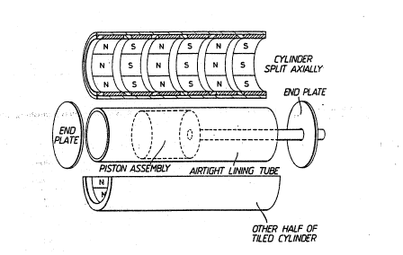
~ One practical method ~f as:sembly is shown in
Fi~ure:~3~ ere;the~outer cylinder:is split into two
hal~es and the~magnet segments are~placed as "tiles" on
the-iexposed inner surface~bf the cy;linder, with suitable
aluminium or plastic spacing elements. The moving-coil
piston unit is then inserted into~:a ~thln non-magnetic
sleeve which;is placed in:one asse~bled half of the
statDr whilst the other hal~ is aligned and ~rought
toget~er:to complete the as~embly.
~ t should be noted that there will be a force
betrJeen the two stator pieces in an axial direction
until the assembly is completed, owing to the tendency
SUBSTITUTE SHEET
WO93/01646 ; ~ ,; PCT/GB92/01277
2113344 - 36 - '
of ~he magnet half rings to seek alignment with half
rings of opposite pol~rity.)
This method of assem~ly is particularly
convenient for the use of moulded ferrite sheet material
which may be formed as flat sheet "striped" with magnets
of alternate polarity. The sheets are simply laid into
the steel half cylinders, into one of which the lining
tube and piston assembly is placed before the two halves
are brought together.
An alternative method of assembly for long
stator tubes is to construct them as modular assemblies
of length equal to two magnet rings and two spacers,
perhaps with a temporary inner steel ring "ke~per ".
Since the modules have no unbalanced magnetic fields
they can be stored, transported and brought together as
necessary to form stator assemblies into which the
airtight liner and plston assem~ly may then be
inserted.
The innovati~e features which we have
described in this document axe:-
The two stage topologi~al transformation ofelectric motor systems to cylindrical actuators~
The design of electromagnetic actuators having
no external fields.
The use of disc or plate magnets to produce
pist~n assemblies. ~ -
The use of radially-magnetized segments to
produce piston assemblies.
The use ~f radially-magne~ized segments to
produce stator sleeves in which a moving coil assembly
moves as a pistonO -~-
The design of rectangular tube thrustassemblies using plate magnets.
The design of solid state commutated coils of
finite width, such ~hat nx=y+21.
SU~STITUTE SHEET
W093/01~6 2113 3 4 4 PCT/GBg2/01277
,, ~ .
-- 37 -- i :
The use of current control in finite width
commutated segments to linearize actuator thrust.
The use of force sensing elements to
compensate ~or unpredictable and/or fast acting variabl~
transient changes in actuator thrust.
The use of accelerometer feedback to control
the current in actuator coils, 50 as to smoothe thrust
variations and to compensate for actuator attitude.
The design of a universal (AC or DC)
electromagnetic actuator system.
The design of linear actuator~ having
travelling waves in both stator and piston, the phase
xelationship between the waves determining the force
acting on the piston.
The use of a phase control to lock the piston
at a node position in such a travelling wave system.
The~design of inductively-coupled cylindrical
piston travelling wave actuator systems.
The use of servo-assisted inductively-coupled
piston actuators for increas~d thrust at low relative
speeds.
The use of phase control to modify th~ force
ana direction of the thrust in an alternating current
bi- or tri-phase~actuator system.
The comhination of Hall-effect commutator
switching and force-feedback thrust control.
The use~ of a~microprocessor and a position
transducer to produce a smooth actuator output thrust by
predict~d current variation.
The ~o~ination of position transducer
pre~etermined curreDt variation and dynamic feedback
from a force-sensing or acceleration-sensing
transducer.
The use of triac switching elements to control
the amplltude and direction of current in commutated
coi 1 elements .
SUBSTITUTE SHE T
WO93/01~6 ~ , PCT/GB92~01Z77
2113344 - 38 - '
A technique of assembly usiny a cylindrical
outer housing split along its length into two or more
pieces to provide easy access to internal areas.
A technique of assembly using a cylindrical
outer housing cut into shorter sections ox modules and
abutted after partial assemhly.
The use of moulded Ferrite material to produce
a single-piece a~sembly of magnets which may be laid in
(each half of) a split steel cylinder skator assem~ly.
The use of moulded Ferrite material to produce
a single-piece assembly of magnets which may be laid
upon (each half of) a steel~cylinder piston asse~bly.
The construction of actuator coils, directly
or as preformed and stacked assemblies, on ribbed
(ringed) steel cylinders to reduce the magnetic
reluctance and to couple the reaction forces to the
thxust components.
,,
.`,
: .
SUBSrlTUTF SHEE~T