Note: Descriptions are shown in the official language in which they were submitted.
CA 02113376 2004-07-26
Device For Securing Rotor Blades Axially And For
Eliminating Rotor Imbalances In Axial-Flow Compressors Or
Turbines
BACKGROUND OF THE INVENTION
This invention relates to a device for axially
securing a moving blade and for eliminating rotor
unbalances in the case of axial-flow compressors or
turbines of gas turbine engines, in which the moving blades
are anchored by means of their blade bases on axial grooves
of a wheel disk distributed along the circumference. Each
axial groove encloses an indentation formed between the
groove bottom and the base end.
A known device of this type is described in European
Patent document EP-A 0437 977. The moving blade operates as
an axial securing device of an unbalance weight, which only
in specific cases can be anchored by means of its exterior
edge end on a recess of the blade base. The moving blade is
approximately crescent-shaped in its cross-section. In this
case, the unbalance weight is situated in an indentation
between the base end and the groove bottom closed by the
blade base on one side. All moving blades are secured only
in one axial direction by a snap ring which
circumferentially extends on the outside between the wheel
rim and the blade base ends. The snap ring engages in this
case on the upper end in grooves of axially projecting
projections of the blade bases.
When a local disk unbalance or rotor unbalance is
determined, the axial securing must first be released and a
concerned moving blade must be pulled out of the axial
groove in order to be able to push the weight, together
with the blade, into the axial groove. The one-sided axial
1
CA 02113376 2004-07-26
blade securing and the weight arrangement, which can be
secured on the blade, require a relatively expensive and
costly fastening of the blade.
A device for axially securing blades known from German
Patent document DE-AS 10 51 286 requires a complicated
blade construction, particularly with a base-side contact
flange by means of which the blade is axially secured in
one direction on a side of the wheel rim. For securing in
the other axial direction, the prior art provides a strip
constructed as a spring steel sheet. Before the
installation of the blade, the strip is inserted in an
axial flute on the groove bottom. The flute forms a one-
sided indentation which is expanded in a diverging manner
toward one wheel rim side. In the position of the strip
which is pressed down with respect to the indentation, the
blade is slid from one side into the axial groove. In a
recess area of the contact flange, the strip, which springs
upward radially out of the indentation, forms a bent stop
which axially secures the blade in the other direction.
Another bent stop of the strip secures it on the wheel rim
on the side facing away from the indentation. In the prior
art, no compensation is provided with respect to
unbalances. This also applies to alternatives of the known
case, according to which, for example, the flute encloses a
uniform indentation along its whole length and the spring
strip has a downwardly directed U-shaped right-angle bend.
SUMMARY OF THE INVENTION
There is therefore needed a device according to the
initially mentioned type, by means of which, without any
special constructive expenditures, two-sided axial blade
securing and controlling of rotor unbalances are achieved
2
CA 02113376 2004-07-26
in a comparatively simple manner, particularly on the blade
bases and on the wheel rim.
According to the invention, these needs are met by
providing a filler piece, which sits on the groove bottom,
and a securing plate, that are inserted in each
indentation. The securing plate bridges a gap between the
base end and the filler piece extending along the
indentation. On the two ends projecting out of the
indentation, the securing plate is bent in a mutually
opposite manner with respect to the faces of the filler
piece, of the wheel disk, and of the blade base. One rotor
unbalance is compensated by at least one filler piece.
More specifically, the present invention provides a
device for axially securing a moving blade and for
eliminating rotor unbalances, the moving blade having a
blade base, comprising a wheel disk having
circumferentially distributed axial grooves, the blade base
being radially and circumferentially anchored in one of the
axial grooves wherein the axial groove encloses an
indentation having a shape formed between a bottom of the
axial groove and a radially anchored end of the blade base,
and a filler piece operatively arranged on the bottom of
the axial groove, and a securing plate having two ends, are
insertable into the indentation, wherein the securing plate
is arranged to bridge a gap formed between the radially
anchored end of the blade base and the filler piece along
an axial length of the indentation with the two ends
projecting beyond the indentation, wherein the securing
plate is bent at each of its two ends in a mutually
opposite manner with respect to end faces of the filler
piece, the wheel disk and the blade base, wherein the
filler piece is selectable as a balancing weight to
compensate for a rotor unbalance at the wheel disk, wherein
3
CA 02113376 2004-07-26
the blade base, the axial groove and the filler piece all
have identical lengths, and wherein the balancing weight is
contoured to the shape of the indentation in order to fill
the gap.
In an installed condition, all filler pieces together
with the respective securing plate completely fill up the
corresponding indentations along the entire axial groove
length, as well as in the cross-section., In this manner, a
good local secondary flow sealing is achieved on the wheel
disk or on the wheel rim. In a relatively simple manner,
the blades and the filler pieces or balancing masses are
simultaneously axially secured on both sides. In a first
installation configuration, all indentations, including
installed securing plates; can be filled up with filler
pieces of a respective identical specific weight. For
example, if a local rotor unbalance or residual unbalance
occurs on the disk, only a tab or an end piece of the plate
has to be bent into a position that is parallel to the
axis. This allows a ffiller piece to be axially pulled out
from one side and replaced by a filler piece with an
unbalance-specific mass which is congruously contoured on
the outside. The invention could therefore also be
implemented in such a manner that first the filler pieces
with the same specific weight, and then the securing
plates, are inserted. Then, the bending of the tabs or end
pieces will take place, with the exception of the
respective above-mentioned one tab or end piece, which has
the purpose of axially securing the plate on one side. In
other words, the balancing takes place in a condition in
which this one tab is in each case still in the position
which is parallel to the axis. After an unbalance is
determined, the concerned filler piece can now be replaced
directly in the axial direction by another filler piece
4
CA 02113376 2004-07-26
which, however, has a deviating specific balancing mass,
whereupon all tabs which project beyond the disk
circumference in parallel to the axis are radially bent.
Furthermore, it is advantageously possible to make
available the securing plates before the mounting with tabs
or end pieces which are already bent on one side. It is a
prerequisite of the above-mentioned measure that the filler
pieces and the securing plates are arranged in the
indentation, between the base end and the groove bottom, by
means of a slightly "tight" fit. Small eyes, bores,
indentations or recesses on the filler pieces can
facilitate the pulling-out for the purpose of an exchange
of weights or for the demounting by means of a tool.
As a result of the illustrated measures, frequent
bending and premature material fatigue of the securing
plates can also be reduced to a minimum. The use of
securing plates and their occasional replacement and of
filler pieces which, with respect to weight, are
coordinated in an unbalance-specific manner, is clearly
less cost-intensive than highly complicated measures which,
as a rule, axially secure the blades only on one side and
which use noses or projections on blades and on the wheel
rim with holding and sealing plates which are inserted
between them along the circumference and which, in
addition, require high mounting expenditures. In the state
of the art, unbalance problems cannot be solved by means of
the latter measures in a manner that is advantageous with
respect to the mounting.
Because of the fact that filler pieces can be used in
the present invention which are softly rounded on the
corners or are approximately semicircular in their cross-
section, and which are coordinated precisely with the
concerned counterfaces of the indentations, a locally large
CA 02113376 2004-07-26
surface loading on the wheel rim can be achieved which is
distributed essentially uniformly.
Other objects, advantages and novel features of the
present invention will become apparent from the following
detailed description of the invention when considered in
conjunction with the accompanying drawings.
BRIEF DESCRIPTION OF THE DRAWINGS
FIG. 1 is a longitudinal sectional view of an installed
and completely mounted device according to the present
invention in an assignment to sections, which are broken
off toward the top and toward the bottom, of a moving blade
and of a wheel disk, with a wheel rim;
FIG. 2 is a top view of the securing plate of FIG. 1 in a
completely extended state;
FIG. 3 is a longitudinal sectional view of an installed
and completely mounted device according to the present
invention in an assignment to sections, which are broken
off toward the top and toward the bottom, of a moving blade
and of a wheel disk with a wheel rim, illustrating a
securing plate which consists of two plate strips and which
is modified with respect to FIG. 1;
FIG. 4 is a lateral view of the securing plate of FIG. 3
in a completely extended state;
FIG. 4a is a top view of the securing plate according to
FIG. 4;
FIG. 5 is a frontal view of a cutout of the wheel rim,
illustrating the completely mounted device according to
FIGS. 1 and 2; and
FIG. 6 is a frontal view of a cutout of the wheel rim,
illustrating the device according to FIGS. 3 and 4.
6
CA 02113376 2004-07-26
DESCRIPTION OF THE PREFERRED EMBODIMENT
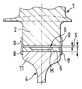
FIGS. 1 to 6 illustrate the device for axially
securing moving blades and for eliminating rotor unbalances
in the case of an axial flow compressor or a turbine of a
gas turbine engine. In this case, the moving blades 1 are
anchored by means of their blade bases 2 on axial grooves 3
of a wheel disk 4. The grooves 3 are uniformly distributed
along the circumference of the wheel disk 4. Each axial
groove 3 contains an indentation T which is formed between
the groove bottom and the blade base end. A filler piece 5,
which sits on the groove bottom, and a securing plate 6 or
12, are to be inserted in each indentation T. The securing
plate 6 or 12 bridges a gap S formed between the base end
and the filler piece 5 which extends along the length of
the indentation T. In the completely installed condition,
the securing plate 6 or 12 is bent on its two ends, which
two ends project out of the indentation T, the wheel disk
or wheel rim 11, and the blade base 2 in a mutually
opposite direction with respect to the faces of the filler
piece 5. A determined rotor unbalance can be compensated
with respect to weight by means of at least one filler
piece 5 of this type.
In a first embodiment of the invention, and applied to
FIGS. 1, 2 and 5, the securing plate 6 has two tabs 8, 9 on
its two ends which are each separated from one another by a
longitudinal slot 7. One tab 9 is bent with respect to the
faces of the blade bases 2 and of a disk hump 10. The other
tab 8 is bent with respect to the faces of the wheel rim 11
and of the filler piece 5.
In FIGS. 3, 4 and 6, the securing plate 12 consists of
two plate strips 13, 14 which are soldered together while
leaving unconnected the end pieces E1, E2. Alternatively,
7
CA 02113376 2004-07-26
they may be welded together with one another, for example,
at points P (FIG. 4). Here, one end piece E1 is, in each
case, bent with respect to a blade base 2 and the faces of
two adjacent disk humps 10. The other end piece E2 is in
each case bent with respect to the filler piece 5 and one
face on the wheel rim 11.
As illustrated particularly in FIG. 5 or 6, the bent
tabs 8, 9 or end pieces El; E2 of the securing plate 6 or
12, additionally form an edge side sealing of the axial
groove 3 and of the indentation T containing the filler
piece 5. Tabs 8, 9 or end pieces El, E2 which are
prefabricated to be longer and wider may further promote
these advantages.
The filler pieces 5, which are always designed to have
a uniform contour, may, for example by means of material
recesses M or M' (FIG. 1) of different sizes, form locally
adapted balancing masses or balancing elements. In this
case, the filler pieces 5 may all be manufactured from a
material with a lower specific weight than the material of
the wheel disk 4.
In order to compensate for an existing rotor or disk
unbalance on the outer circumference of the wheel rim 11 of
the wheel 4, the concerned filler piece, which can be
selected as the balancing element, may be equipped with an
unbalance-specific material filling 20. This may be a
filling of lead shot or the like. The filling may be
entered into a recess or blind hole bore of the respective
filler piece which can be closed off from the outside. The
required balancing element may be made available according
to the size of the bore and thus the amount of the filler.
It is also possible, for example, to construct the
filler pieces 5 from a stainless steel or from a technical
ceramic material or from a plastic material reinforced by
8
CA 02113376 2004-07-26
fibers. In the case of metallic materials, suitable
stamping processes may be used, during which the required
sizes and types of the recesses or of the beads or nubs in
the recesses can be prefabricated at the same time. In each
case, this results in unbalance-specific adaptations.
For implementing the invention, it is advantageous for
suitable depositing devices to be made available for the
filler pieces 5. Weight classifications are assigned to the
depositing devices so that the required filler piece can be
picked out rapidly as the balancing element.
As illustrated in FIGS. 2, 3, 5 and 6, the filler
pieces 5 are constructed to be adapted to the length and
shape of the indentation T, between the securing plate 6 or
12 and the groove bottom. In this case, the filler pieces
5, at least partially along their longitudinal course, by
means of a cross-section which is softly rounded on the
corners or is approximately semicircular, are laterally and
on the bottom held in the indentation T (FIG. 6).
As also illustrated in FIG. 6, securing plate 12
consists of two plate strips 13, 14 of different widths. In
this manner, the securing plate 12 is adapted to the
diagonal contour courses of the indentation T or the axial
groove 3 and, when the fit is good, the sealing is thereby
optimized.
According to FIGS. 3 and 4, the securing plate 12 is
composed of two plate strips 13, 14 of different lengths
with respect to the end pieces E1, E2 to be bent.
Among other things, a simplified mounting is achieved
by the fact that the respective securing plate 6 or 12 can
be used with tabs 8, 9 or end pieces E1, E2 which are
already bent in opposite directions to one another on one
end.
9
CA 02113376 2004-07-26
In the case of the present invention, it is not
necessary for the removal or installation of a filler piece
to displace the respective moving blade 1 relative to the
axial groove 3 or even to have to remove the blade 1 from
the axial groove 8. Analogously, this also applies to the
removal or installation of the securing plate 6 or 12.
The mounting takes place such that all successively
moving blades 1, then all filler pieces 5, with an, at
first, respective identical own weight, and then all
securing plates 6 or 12 are inserted. Finally, the blades
as well as the filler pieces are bent on both sides in an
axially securing manner. According to FIG. 3, one end piece
E2 may be left to be axially free-standing. When a rotor
unbalance occurs, a "light" filler piece contained in the
respective indentation T is replaced directly, and by
itself by a heavier filler piece 5, and only then are all
end pieces E2 bent radially.
By way of the axial grooves 3, the inserted moving
blades 1 are anchored radially as well as in the
circumferential direction. The geometry of the blade bases
2 and the respectively coordinated axial grooves 3, as
illustrated, may be in the shape of a Christmas tree base
or of a dovetail or of a hammer head.
The securing plate 12 (FIG. 4, 4a) may also be used by
means of plate strips 13, 14 which are not completely
connected with one another and have, for example, the same
length and the same width.
Although the invention has been described and
illustrated in detail, it is to be clearly understood that
the same is by way of illustration and example, and is not
to be taken by way of limitation. The spirit and scope of
the present invention are to be limited only by the terms
of the appended claims.