Note: Descriptions are shown in the official language in which they were submitted.
Closure Unit ~ 2 ~
The invention is in the field of the packaging industry and
relates to a closure unit and to a process for its
production according to the preambles of the corresponding
independent claims.
On containers for liquids, such as e.g. metal cans or
receptacles made from coated or laminated cardboard, for the
purpose of a resealable opening and for easy pouring, use is
often made of closure units, preferably made from plastic
and comprising a pouring part with a pouring opening and a
closure part closing the pouring opening of .he pouring part
and fitted into an opening of the container.
Such closure units are made from plastic, which is
inexpensive and has favourable characteristics for the
manufacture of the closure unit. It enables manufacture to
take place with tools so as to permit a considerable output.
The aim is that the closure unit only insignificantly
increases the container price and consequently the container
with the closure unit appears attractive to the user from a
maximum number of standpoints. However, it can occur that
the product in the container has to be siven additional
protection against influences from the en~ironment, so that
it can be kept longer. Such influences which can
unfavourably influence the product are e.g. environmental
moisture and air, together with light or radiation of other
types. It is also possible for gases, such ~s waste gases,
which are mixed with the environmental air, to unfavourably
influence foods in such containers and oxidize the vitamins
contained therein or modify the taste of such foods.
Therefore it can be desirable to provide such containers
with coatings, which do not permit the passage of gases
and/or light.
21 1 3423
The closure unit must also satisfy the requirements
generally made on the container. In this sense the
procedure has hitherto been such that either the opening in
the container or the opening in the closure unit is covered
with a foil or film, which must be
2 1 1 3423
destroyed at the time of the initial pouring out or removal
of the product.
The disadvantages of this solution is that said film or
foil, has to be removed or perforated at the time of the
initial pouring out and that it subsequently can no longer
fulfil its intended function, i.e. it is for example no
longer gas-tight or is no longer impervious to light. It
can also no longer fulfil its function if a closure part of
- the closure unit again firmly closes the pouring opening,
because on closing the closure part the film or foil is not
restored to its original state. Therefore, the container
as a whole, has lost part of its characteristics as a
result of the initial opening of the closure unit in the
same way as for a cont~iner not having a closure unit and
is also accepted, because it would appear to be
unavoidable.
The invention, as characterized in the claims, solves the
problem of providing a closure unit for a container, with
which the original characteristics of the container and
which are essential for protecting the product, remain
substantially unchanged even after the closure unit has
been opened several times. In particular, the invention
solves the problém of providing a closure unit for a
container, which also in the closed state is substantially
gas-tight and/or radiation-impermeable, even if the closure
has already been opened.
According to an aspect of the invention this is achieved in
that during the manufacture of the closure unit and in a
further stage, one or more coatings are applied to the
inside, to the outside or to both the inside and outside of
the closure unit. These coatings adhere to the pouring
,,~,~
21 1 3423
part and to the closure part and consequently bridge a gap
between the pouring part and the closure part in the form of
a thin membrane or at least partly fill the same. At the
time of the initial opening of the closure part the coating
is only interrupted at this comparatively very small gap and
cannot be restored again following closing. As a result of
a planned design of the closure unit at said gap or
separation point, it can be ensured that in spite of this it
is possible to substantially maintain the requisite
characteristics such as e.g. a gas and/or radiation seal.
Another aspect of this invention is as follows:
A closure unit made from thermoplastic material for
subsequent attachment to a container for the handling and
storage of a flowable product comprising
a substantially tubular pouring part having a wall
defining an opening;
an openable and reclosable closure part closing said
opening of said pouring part, and
at least a first coating extending continuously over
both an inner surface of said openable and reclosable
closure part and an interior surface of said wall defining
said opening of said pouring part, said first coating
protecting the product against undesired influences.
The advantages resulting from the invention are in
particular that the demands made on the container for the
protection of the product are still maintained if further
functions are to be performed with the container. In
, ~
,
21 1 3423
- 3a -
other words, if with respect to the product which it is
to contain, the container has to perform several
functions such as e.g. protecting the product against
external influences, product handling, product storage,
etc., one of these functions is not impaired if or
because another of the intended functions is fulfilled.
Therefore each function is independently maintained
compared with the other functions or characteristics.
This is not the case in the known containers, where the
performing of one function necessarily impairs the other
functions. For example, a handling of the product, such
as its partial removal from the known container, then
impairs the container protection function. In the case
of the container with the closure unit according to the
invention, this is not the case. An important advantage
of the solution according to the invention is that the
application of the coatings can be integrated into the
manufacturing process for the closure unit. Thus, it is
possible to manufacture a finished closure unit having
all the desired properties and this can be subsequently
fitted to a container. The invention also makes it
possible to adapt the characteristics of the container
and closure unit together to the most varied conditions.
Thus, it is possible to provide a first coating, which
fulfils in optimum manner a first condition (e.g. light
seal or oxygen e~chAnge barrier). However, if this
coating can be me~h~n;cally damaged, e.g. by granular
material in the container, then a further coating can be
provided, which protects the first coating against
mech~nical damage. A third coating can be provided,
which has further supplementary properties, etc.
Therefore the individual coatings are allocated
characteristics or functions,
i~
_ 4 _ 2 1 1 3 ~ 2 3
which they fulfil in an optimum manner and the missing properties
can be supplemented by additional coatings, which in turn fulfil
in optimum manner said supplementary properties. Thus, it is possi-
ble to fulfil in an optimum manner a large number of conditions
applied to the container and closure unit. The reduced properties
with respect to the gap between the pouring part and the closure
part can, as stated, at least partly be compensated by other meas-
ures. Even if this is not always possible, then the surface parts
which do not completely fulfil said characteristics, are negligibly
small with respect to the inner face of the container.
The invention is described in greater detail hereinafter relative
to the drawings, wherein show:
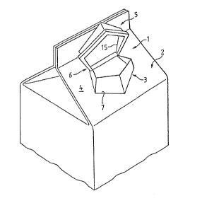
Fig. 1 a container with a closure unit in a perspective view.
Fig. 2 a closure unit in section.
Fig. 1 shows a closure unit 1, which is placed in a cardboard cont-
ainer 2. The closure unit 1 comprises a pouring part 3, which proj-
ects from one face 4 of the container 2 and also a closure part
5, which is shown here in the open state. The closure part 5 and
the pouring part 3 are non-detachably interconnected by means of
a hinge 6. The face 4 has an opening 7 in which is inserted the
closure unit 1 and in the presently illustrated example the closure
unit must be pushed through the opening 7 from the container interior
before being fixed to the wall 4, e.g. by ultrasonic welding.
Fig. 2 shows a section through the closure unit 1 of fig. 1, where
it is possible to see the pouring part 3, the closure part 5 and
a hinge 6. The construction shown has various additional details,
which are not essential to the invention, but which are represented
in order to show a completely functioning closure unit. Such a
detail is e.g. a predetermined breaking point 11, which is destroyed
on the initial opening and forms the actual gap or separating point
between the pouring part 3 and the closure part 5. The closure
2113~23
-- 5 --
unit also has sealing faces 8, which are located between the pouring
part 3 and the closure part 5, where said two parts cover one anot-
her. It is also possible to see a foot 9, which is fixed to the
pouring part 3 and which forms a face 10 by means of which the clos-
ure unit 1 can be fixed in the wall 4 (fig. 1). Bonding, adhesion
or welding can be used for fixing purposes. It is also possible
to see a first coating 12, which is here only applied to the inside
13 of the right-hand half of the closure unit and which is covered
by a further coating 14. It is also possible to see an external
coating 19, which here extends both over the closure part 5 and
the pouring part 3.
On the initial opening of the closure part 5, the coating 12,14
is destroyed in the vicinity of the predetermined breaking point
11 and which in fig. 1 roughly follows the line 15. However, the
outer coating 19 is torn or interrupted in the vicinity of a point
20. The exemplified construction of the closure unit 1 shown ensures
that the action of this destruction remains extremely small, because
the closure unit 5 so closely surrounds the pouring part 3 in the
vicinity of the sealing faces 8, that, even without a coating, the
closure unit 1 is tight with respect to the passage of gas or liquid.
This is assisted by further baffles, designated 16 and 17 and which
form additional corners and faces, which e.g. improve the sealing
action. If the coating 12,14 of the closure unit 1 is to be improved
with respect to the diffusion of gas or liquid through its walls,
said action is maintained by the intact coating 12,14 over the entire
remaining inner face 13. In the vicinity of the predetermined break-
ing point 11 the material thickness is at least doubled, so that
the diffusion is also significantly inhibited by the increased mater-
ial thickness at the point where the coating is damaged. The same
action is also obtained in the vicinity of the separation point
11 with respect to radiation, diffusion, etc. If the coatings are
in particular provided for stopping the diffusion of gases or the
passage of rays, then an inner and outer coating is particularly
effective, because both act in large-area form and do not have their
- 6 - 2113~23
separation point 11,20 at the same location, so that one coating
covers the separation point of the other coating.
Such a closure unit 1 is fixed by means of the foot 9 to the cont-
ainer 2. If this takes place by welding, then in an area 18 it
is necessary to weld through the coating, which can consequently
be destroyed at this point. However, in the said area 18 the mater-
ial from which the foot 9 and the wall 4 is formed is modified,
e.g. compacted by the welding process, so that this effect compen-
sates the lost action of the coating. If this is not the case,
it is e.g. possible to use adhesion, so that the coating remains
intact. Welding interrupts the coating, whereas adhesion or bonding
bridges the coating.
The coatings 12 can be made from the most varied materials and those
made from mineral substances are particularly favourable. This
leads to a glassy coating, which is chemically neutral and can there-
fore come into contact with the most varied materials without reac-
ting. Glassy coatings are also very suitable for preventing an
undesired gas exchange. To protect the product against the influ-
ence of radiation or electric and magnetic fields, coatings made
from metallic materials are very suitable. As a further coating
14 can be provided plastic coatings, which e.g. offer protection
to thermal and mechanical influences. Thus, it is possible to supp-
lement the characteristics of the metal coating, which are relatively
damage-prone, in that they are given the necessary damage protection.
The coatings can be provided internally on the closure unit, i.e.
on the inner face 13, as well as on the outer face or on both faces.
The coatings have a thickness extending from a few Angstrom to a
few tenths of a mm, as a function of the coating type and the task
which it has to fulfil.
In the case of the process of the invention for the production of
the closure unit firstly the closure unit 1 is produced e.g. by
2113~23
-- 7 --
moulding in per se known manner. Subsequently the closure unit
is provided with a first coating in a further, per se known device
and this preferably takes place with the closure part closed. Then
in the same or a different device a further coating is applied.
The devices used depend on the nature and material of the coating.
If e.g. an aluminium coating is provided, then this takes place
in a device for the vacuum deposition of aluminium. Coatings based
on silicone oxides, which are relatively hard, can be produced by
application in a plasma. This is very advantageous, because the
process need not take place at high temperatures. Plastic coatings
can be sprayed on.
As the coatings can be of the most varied types and as the production
or application of the coating is greatly dependent on the coating
type, the possibilities available have not been exhaustively discu-
ssed, but are covered by the scope of the invention.