Note: Descriptions are shown in the official language in which they were submitted.
DAIA:077
21~.~~5~
10
A DOUBLE-ACTING ACCELERATOR FOR UBE WITH
HYDRAULIC DRILLING JARS
This invention relates generally to an accelerator
for use with hydraulic jars in a drilling environment
and, in particular, to a double acting accelerator for
use with double acting hydraulic jars.
Drilling/jars have long been known in the field of
well drilling equipment. A drilling jar is a tool
employed when either drilling or production equipment has
become stuck to such a degree that it cannot be readily
dislodged from the wellbore. The drilling jar is
normally placed in the drill string in the region of the
stuck object and allows an operator at the surface to
deliver a series of impact blows to the drill string via i
a manipulation of the drill string, such as by lowering
and raising the drill string. Hopefully, these impact
blows to the drill string are sufficient to dislodge the
stuck object and permit continued operation.
Drilling jars contain a sliding joint which allows
relative axial movement between an inner mandrel and an
outer housing without allowing rotational movement
therebetween. The mandrel typically has a hammer formed
thereon, while the housing includes an anvil positioned
adjacent the mandrel hammer. Thus, by sliding the hammer
and anvil together at high velocity, they transmit a very
211~4~~
-2-
substantial impact to the stuck drill string, which is
often sufficient to jar the drill string free.
In some instances it is desirable to greatly enhance
the force of the impact blows so that a much larger
hammering force can be applied to a stuck object.
Typically, the force of the drilling jar has been
enhanced by adding an accelerator to the drill string.
The accelerator is used to store energy until the jar is
triggered. When the jar is triggered, the accelerator
quickly releases its stored energy and accelerates the
hammer of the drilling jar to a very high speed. The
force of the impact is, of course, related to the square
of the velocity, thus, the hammer force is greatly
enhanced by the accelerator.
Recently, drilling jars have been developed that are
capable of delivering hammer blows in both an upward and
downward direction. For example, U.S. Patent No.
4,361,195, issued November 30, 1982, to Robert W. Evans,
describes such a double acting drilling jar.
Heretofore, double acting accelerators have not been
available to cooperate with double acting drilling jars.
Thus, it has not been possible to deliver enhanced upward
and downward hammer blows with these double acting
drilling jars.
The present invention is directed to overcoming or
minimizing one or more of the problems discussed above.
In one aspect of the present invention, a double
acting accelerator is provided. The accelerator includes
a tubular housing, and a tubular mandrel substantially
coaxially arranged for telescoping longitudinal movement
within the tubular housing. A first piston is positioned
CA 02113458 2002-12-23
-3-
radially between the tubular housing and mandrel and is adapted
for movement with the mandrel in response to movement of the
mandrel in a first longitudinal direction relative to the
housing. Further, the first piston is also adapted to resist
longitudinal movement in response to movement of the mandrel in
a second longitudinal direction relative to the housing. A
second piston is positioned radially between the tubular housing
and mandrel and with the first piston forms a substantially
sealed chamber therebetween. The second piston is adapted for
movement with the mandrel in response to movement of the mandrel
in the second longitudinal direction relative to the housing and
adapted to resist longitudinal movement in response to movement
of the mandrel in the first longitudinal direction relative to
the housing. Thus, the chamber has an increase in pressure in
response to movement of the mandrel in both the first and second
longitudinal directions relative to the housing.
Other aspects and advantages of the invention will become
apparent upon reading the following detailed description and
upon reference to the drawings in which:
Figs. 1A - C illustrate successive portions, in quarter
section, of a double acting accelerator located in its neutral
operating position.
Figs. 2A - C illustrate successive portions, in quarter
section, of the accelerator in its downward operating position
Figs. 3A - C illustrate successive portions, in quarter
section, of the accelerator in its upward operating position.
-4-
While the invention is susceptible to various
modifications and alternative forms, specific embodiments
thereof have been shown by way of example in the drawings
and will herein be described in detail. It should be
understood, however, that this specification is not
intended to limit the invention to the particular forms
disclosed herein, but on the contrary, the intention is
to cover all modifications, equivalents, and alternatives
falling~within the spirit and scope of the invention, as
defined by the appended claims.
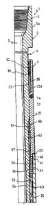
Referring to the drawings, and in particular, to
Figs. 1A-C, inclusive, there is shown a double acting
accelerator 1, which is of substantial length
necessitating that it be shown in three longitudinally
broken quarter sectional views, viz. Figs. 1A, 1B, and
1C. Each of these views is shown in longitudinal section
extending from the center line (represented by a dashed
line) of the accelerator 1 to the outer periphery
thereof. The accelerator 1 generally comprises an inner
tubular mandrel 2 telescopingly supported inside an outer
tubular housing 3. The mandrel 2 and housing 3 each
consists of a plurality of tubular segments joined
together preferably by threaded interconnections.
The mandrel 2 consists of an upper tubular portion.4
having an inner longitudinal passage 5 extending
therethrough. The upper end of the upper tubular portion
4 is enlarged as indicated at 5a and is internally
threaded at 6 for connection to a conventional drill
string or the like (not shown). The lower end of the
upper tubular portion 4 is provided with a counterbore
ending in an internal shoulder 7 and is internally
threaded as indicated at 8. An intermediate portion of
the mandrel 2 consists of a tubular portion 9 which has
-5-
its upper end threaded as indicated at 10 fox connection
inside the threaded portion 8 of the upper tubular
portion 4 with the upper end portion abutting the
shoulder 7. The lower end of the tubular portion 9 is
threaded externally as indicated at 11 and is provided
with an internal bore or passage 12, which is a
continuation of the passage 5 in the upper tubular
portion 4. The lower end of the mandrel 2 consists of a
tubular portion 13, which is provided with a counterbore
ending in a shoulder 14 and internally threaded as
indicated at 15. The tubular portion 13 is threadedly
assembled to the lower end of the tubular portion 9, with
the lower end thereof abutting the shoulder 14.
The lower end portion of the tubular portion 13 is
threaded as indicated at 16. A sleeve member 17 having
internal threads 18 is tfireadedly secured on the lower
end of the tubular portion 13. The tubular portion 13 is
provided with an internal longitudinal passage 19 which
2o is an extension of the passages 5, 12 and opens through a
central opening 20 of the sleeve member 17. The three
portions 4, 9, 13 of the mandrel 2, are threadedly
assembled, as shown, into the unitary tubular mandrel 2,
which is longitudinally movable inside the tubular
housing 3.
The tubular housing 3 is formed in several sections
for purposes of assembly, somewhat similar to the mandrel
2. The upper end of the tubular housing 3 consists of a
tubular member 21 which has a smooth inner bore 22 formed
by a conventional bearing 22a at its upper end in which
the exterior surface of the upper mandrel tubular portion
4 is positioned for longitudinal, sliding movement. The
lower end portion of the tubular housing member 21 has a
portion of reduced diameter forming an annular shoulder
23 and having an exterior threaded portion 24.
The tubular housing 3 is provided with an
intermediate tubular member 25 which is internally
threaded as indicated at 26 at its upper end for threaded
connection to the threaded portion 24 of the tubular
member 21. The upper end of the intermediate tubular
member 25 abuts the shoulder 23 when the threaded
connection is securely tightened. The lower end portion
of the tubular member 25 has a portion of reduced
diameter forming a shoulder 27 and is externally
threaded, as indicated at 28.
The lower portion of the tubular housing 3 consists
of a tubular member 29 which is internally threaded, as
indicated at 30, at its upper end for connection to the
threaded portion 28 of the intermediate tubular member
25. The upper end of the lower tubular member 29 abuts
the shoulder 27 when the threaded connection is securely
tightened. The lower end of the tubular member 29 is
internally threaded, as indicated at 31.
A tubular member 29a has a portion of reduced
diameter forming a shoulder 27a and is threadedly
connected at its upper end to the threaded portion 31 of
the tubular member 29 in abutting relation with the
shoulder 27a. The lower end of the tubular member 29a
includes a threaded portion 31a engageable with a tubular
connecting member 32. The tubular connecting member 32
is externally threaded, as indicated at 33, at its upper
end and has a shoulder 34 against which the lower end of
the tubular member 29a abuts when the threaded connection
31a, 33 is securely tightened. The tubular connecting
member 32 has an inner longitudinal passage 35 which is a
continuation of the passages 5, 12, 19 through the
mandrel 2. The lower end of the tubular connecting
member 32 is of a reduced diameter and is provided with
an externally threaded surface 32a for connection into
2113~5~
the lower portion of a drill string or for connection to
a fish, or the like (not shown), when the apparatus is
used with a fishing jar.
As has already been noted, the mandrel 2 and housing
3 are formed in sections for purposes of assembly. The
mandrel 2 is arranged for sliding movement inside housing
3. A chamber formed between the mandrel 2 and housing 3
is filled with a suitable operating fluid that is
preferably compressible, e.g. silicone, and it is
therefore necessary to provide seals against leakage from
threaded joints formed at the various sections of the
mandrel 2 and housing 3 and also from the points of
sliding engagement between the mandrel 2 and housing 3.
As previously noted, the exterior surface of the
upper mandrel portion 4 has a sliding fit in the bore 22
of the upper tubular member 21 of the housing 3. The
tubular member 21 is provided with at least one internal
annular recess 38 in which there is positioned at least
one seal 39, which seals the sliding joint against
leakage of hydraulic fluid. Likewise, the threaded
connection between the tubular housing members 21, 25 is
sealed against leakage by an 0-ring 40, or the like,
positioned in an external peripheral groove 41 in the
lower end of the tubular housing member 21. The threaded
connection between the tubular housing members 25, 29 is
similarly sealed against fluid leakage by an O-ring 42
positioned in a peripheral groove.43 in the lower end
portion of the tubular housing member 25. Likewise, the
threaded connection between the tubular housing members
29, 29a is sealed against fluid leakage by an O-ring 42a
positioned in a peripheral groove 43a in the upper end
portion of.the tubular housing member 29a.
2113~~~
Finally, the threaded connection between the lower
end of the tubular housing member 29a and the connecting
member 32 is similarly sealed against leakage of fluid by
an O-ring 46 positioned in an peripheral groove 45 in the
upper end of the connecting member 32. Similar seals are
provided to prevent leakage through the threaded joints
connecting the several sections of the mandrel 2.
The space between the inner bore of the various
components of the housing 3 and the external surface of
the mandrel 2 provides an enclosed chamber and passages
for the flow of operating fluid, such as silicone,
throughout the accelerator.
At the upper end of the tubular housing member 21,
the space between an inner bore 50 thereof and an
externah surface 51 of the tubular mandrel portion 4
provides a chamber 52. The upper end of the chamber 52
is provided with a threaded opening 53 in which a
. threaded plug member 54 is secured. The threaded opening
53 provides for the introduction of the operating fluid.
The exterior surface of the tubular mandrel portion
4 is of slightly reduced diameter at a lower end portion
55 thereof, and is provided with a plurality,.of
longitudinally extending grooves 56 forming splines
therebetween. The lower end portion of the tubular
housing member 21 is provided with an inner bore 57
having a plurality of longitudinally extending grooves 59
therein and circumferentially spaced to define a
plurality of splines therebetween to interact with the
splines and grooves 56 in the upper. tubular mandrel
portion 4. The grooves 56, 59 in the tubular housing
member 21 and in the tubular mandrel portion 4 are of
greater depth than the height of the opposed splines
positioned in those grooves 56, 59. As a result,
2~~3~~8
_g_
longitudinal passages are provided along the respective
grooves 56, 59 in the mandrel portion 4 and the housing
member 21. The passages formed by the clearance between
the splines and grooves 56, 59 permit operating fluid to
flow between the chamber 52 and the lower portions of the
accelerator 1.
Additionally, the arrangement of longitudinally
extending splines and grooves 56, 59 in the tubular
housing member 21 and on the tubular mandrel portion 4
provides a guide for longitudinal movement of the mandrel
2 in the housing 3 without permitting rotary movement
therebetween.
The clearance between the tubular housing member 25
and the mandrel portions 4, 9 is such that there is
provided a hydraulic chamber 63 of substantially enlarged
size relative to the hydraulic chamber 52. In one
embodiment, this enlarged chamber 63 operates as a fluid
reservoir for a main operating chamber, described in
detail below.
The tubular mandrel portion 9 is provided with a
plurality of longitudinally extending grooves 76. The
grooves 76 provide flow passages for the flow of
operating fluid, as will be subsequently described. A
'spacer ring 77 is supported on the tubular mandrel
portion 9 and has an internal surface 78 spaced from the
exterior surface of the mandrel portion.9 to provide an
annular flow passage 79.
The spacer ring 77 is provided with apertures 80
which open~from the passage 79 into the hydraulic chamber
63. The lower end of the passage 79 also overlaps the
upper end of the grooves or passages 76 to provide for
continuous fluid communication between the hydraulic
-lo- ~113~58
chamber 63 and the grooves 76. The upper end of the
spacer ring 77 abuts the lower end of the tubular mandrel
portion 4. The lower end of the spacer ring 77 is, in
turn, abutted by the upper end of a tubular portion 82,
which fits over the external surface of the mandrel
portion 9 in which the grooves 76 are formed. The
tubular portion 82, therefore, encloses the grooves 76
and deffines a system of longitudinally extending
passages. The lower end of the tubular portion 82 abuts
an annular spacer ring 83, which is provided with a
plurality of apertures 84 opening into the ends of the
grooves or passages 76.
An inner surface 86 of the housing member 29 and an
outer surface 87 of the tubular portion 82 are spaced
apart to define a hydraulic chamber 88, which is the main
operating chamber mentioned above. Generally, the
operating fluid within chamber 88 resists relative
movement of the mandrel 2 and housing 3. That is,
relative movement of the mandrel 2 and housing 3 reduces
the volume of the chamber 88, causing a significant
increase in the internal pressure of the fluid within
chamber 88, thereby producing a force to resist this
relative movement. This resistance to relative movement
allows a large buildup of static energy. Thus, when the
force urging the housing 3 is suddenly removed, as by
tripping of the associated drilling jar, the static
energy is converted to kinetic energy, causing the
mandrel 2 and housing 3 to move rapidly and accelerate a
hammer within the associated drilling jar (not shown) to
strike an anvil surface with great force. It should be
appreciated that this buildup of static energy is
accomplished by movement of the mandrel 2 relative to the
housing 3 in either longitudinal direction.
2113~~8
-11-
Preferably, the operating fluid is selected from a
group that is relatively compressible. For example,
liquid silicone is preferred because it is substantially
more compressible than conventional hydraulic fluid. It
should be appreciated that it is the compression of the
fluid that stores the energy in the accelerator.
Additionally, any of a variety of compressible gases,
such as nitrogen gas may also be used as the compressible
fluid without departing from the spirit and scope of the
instant invention.
Accordingly, means is provided for substantially
sealing the chamber 88 to permit this buildup of pressure
therein. The surfaces 86, 87 of the chamber 88 are
smooth cylindrical surfaces, permitting free movement of
a pair of pressure pistons supported therebetween and
defining the chamber 88. At the upper end of the
hydraulic chamber 88, an annular pressure piston 89 is,
positioned between the surfaces 86, 87 for sliding
movement therebetween. The piston 89 is sealed against
fluid leakage by o-rings 90, 91 positioned in annular
grooves 92, 93, respectively. Movement of the piston 89
is caused by engagement with the mandrel 2 and, in
particular, a shoulder formed by the end of the spacer
ring 77. That is, downward movement of the mandrel 2 and
spacer ring 77 engages the piston 89 and urges it
downward. Alternatively, the lower end of the tubular
housing member 25 forms a shoulder that prevents upward
movement of the piston 89. Thus, the longitudinal
position of the piston 89 is affected by movement of the
mandrel 2 in only the downward direction.
In one embodiment, the piston 89 is provided with at
least one passage 94 to permit a small leakage flow of
operating fluid therethrough. This leakage flow from the
chamber 88 to the chamber 63 occurs during thermal
2~~3~~8
-12-
expansion of the operating fluid as the accelerator 1 is
lowered into the wellbore. However, during jarring, only
a very small amount of operating fluid passes through the
passage 94.
The lower end of the chamber 88 is similarly sealed
by an annular pressure piston 111, which is substantially
similar to the piston 89. The piston 111 is sealed
against outward flow from the chamber 88 by a
conventional one-way check valve 112. Also, the piston
111 is moveable upwards by engagement with the annular
spacer ring 83 during movement of the mandrel 2 upward
and out of the housing 3. The upper end of the tubular
housing member 29a forms a shoulder that engages the
piston 111 and.prevents downward movement thereof. The
check valve 112 permits the replacement of the very small
amount of fluid that leaked through the passage 94 during
a previous jarring action. That is, after a jarring
action, the pressure in the chamber 110 exceeds that in
the chamber 88. Thus, fluid flows from the chamber 110,
through the check valve 112, and into the chamber 88,
thereby restoring the volume of fluid in the chamber 88
to its pre-jar level.
The mandrel 2 and housing 3 are urged to remain in
the central or neutral position illustrated in Figs. lA-C
by a pair of coil springs 118, 119. The coil springs
118, 119 are coaxially positioned about the tubular
portion 82 within the chamber 88 and respectively extend
between the pressure pistons 89, 111 and a pair of
radially extending flanges 120, 121. In particular, the
flanges 120, 121 form shoulders 122, 123 against which
the coil springs 118, 119 rest. The springs 118, 119
also operate to urge the pistons 89, 111 toward the ends
of the chamber 88 and to maintain the accelerator l in
its central or neutral operating position.
2~~345~
-13-
A floating piston 109 is positioned in sealing
relationship between the mandrel portion 13 and the
tubular member 29a to isolate a hydraulically filled
chamber 110 from the internal passage 35. The chamber
110 is hydraulically connected to the grooves 76 through
the plurality of apertures 84. Thus, the chamber 110 is
in hydraulic communication with the chambers 52, 63 to
form a substantial fluid reservoir for the operating
chamber 88. The floating piston 109 moves longitudinally
within the chamber 110 to accommodate pressure changes
between the chambers 52, 63, 110 and the internal passage
35. These pressure changes are ordinarily associated
with variations in the temperature of the operating
environment.
A better appreciation of the operation of the
accelerator 1 may be had by reference to Figs. 2A-C,
where a cross sectional view of the accelerator 1 in its
downward operating position is shown. The interaction
and movement of the various components of the accelerator
1 may best be appreciated by a description of its
operation during an actual downward and upward
acceleration. Therefore, referring now to Figs. 2A-C,
the movement of the various components of the accelerator
1 during a downward acceleration is illustrated and
discussed.
It should be appreciated that a significant
operation occurring in the accelerator 1 is the operation
and interaction of the pistons 89, 111. Accordingly, the
operation of the pistons 89, lli is discussed in detail
in conjunction with the drawings illustrated in Figs. 2A-
C. Further, a description of the accelerator 1 in its
neutral position has already been shown and discussed
with respect to Figs. lA-C.
2113~~8
-14-
The accelerator 1 operates to enhance the hammering
action of a drilling jar by storing a large amount of
energy therein, which is released in response to the jar
being triggered. Accordingly, before a downward jarring
action can be initiated, it is first preferable to "arm"
the accelerator 1 by placing a portion of the weight of
the drill string onto the accelerator 1 and jar. Figs.
2A-C illustrate the mandrel 2 and, consequently, the
spacer ring 77 moved downward relative to the housing 3
and; in particular, to the tubular member 29. This
downward movement is, of course, caused by the weight of
the drill string resting thereon.
The mandrel 2 has moved sufficiently far downward
that the spacer ring 77 has longitudinally moved into the
chamber 88, carrying the upper piston 89 therewith. The
spacer ring 77 has carried the piston 89 into the chamber
88, thereby compressing the fluid in the chamber 88. The
lower piston 111, however, has contacted the upper end of
the tubular housing member 29a, preventing further
longitudinal movement thereof. It should be appreciated
that if a relatively non-compressible hydraulic fluid
were to be is used in the chamber 88, then only
relatively minor movement would occur.
The coil spring 118 is shown to be relatively
uncompressed, owing to the lack of longitudinal movement
between the piston 89 and flange 120. The coil spring
119, on the other hand, is highly compressed, owing to
the longitudinal movement between the piston 111 and
flange 121.
At this point, the accelerator 1 is fully °'armed"
and prepared to accelerate the hammer of the jar in
response to the jar being triggered. In this downward
actuation, the mandrel 2 has been forced into the housing
3 by placing the weight of the drill string onto the
2113~~~
-15-
accelerator 1. When the jar triggers, the support for
the housing 3 is removed and the housing 3 is free to
move downward with the hammer of the jar. However, the
accelerator 1 enhances this downward movement. Since the
jar below no longer resists downward movement of the
housing 3, then the pressurized fluid in the chamber 88
is free to expand and force the housing 3 downward along
with the hammer of the jar. This forced expansion
greatly enhances the hammering force of the jar.
Referring now to Figs. 3A-C, an upward actuation of
the accelerator 1 is described. Once again, the upward
actuation is proceeded by the accelerator 1 being
positioned in its neutral position, as shown in Figs. 1A-
C. An upward actuation begins by the mandrel 2 being
withdrawn or pulled upward and out of the housing 3.
Upward movement of the mandrel 2 causes the spacer ring
83 to engage the lower piston 111 and move the piston 111
upward with the mandrel 2.
Movement of the piston 111, of course, reduces the
volume of the chamber 88 since the upper piston 89 is
prevented from moving upward by engagement with the lower
end of the tubular housing member 25. Thus, this
movement begins to drastically increase the pressure
therein. As discussed previously, a small amount of
hydraulic fluid is allowed to leak from the chamber 88
through the upper pressure piston 89, thereby permitting
continued gradual movement of the mandrel 2 upward and
out of the housing 3.
The coil spring 119 is shown to be relatively
uncompressed, owing to the lack of longitudinal movement
between the piston 111 and flange 121. The coil spring
118, on the other hand, is highly compressed, owing to
~113~58
-16-
the longitudinal movement between the piston 89 and
flange 120.
At this point, the accelerator 1 is fully "armed"
and prepared to accelerate the hammer of the jar in an
upward direction in response to the jar being triggered.
In this upward actuation, the mandrel 2 has been forced
from the housing 3 by lifting the drill string. When the
jar triggers, the housing 3 is no longer held downward by
the jar and drill string there below. Thus, the fluid in
the chamber 88 is free to expand and pull the hammer of
the jar rapidly upward. This forced expansion greatly
enhances the upward hammering force of the jar.
In an alternative embodiment of the accelerator 1,
the chamber 88 is isolated from the chambers 52, 63, 110
so that a different operating fluid may be employed in
the operating chamber 88 from that used in the chambers
52, 63, 110. In the first embodiment described above,
the operating fluid used throughout the accelerator 1 is
preferably silicone, which tends to have poor lubricating
qualities when compared to conventional hydraulic fluid,
but is preferable for its greatly enhanced
compressibility over that of conventional hydraulic
fluid. Therefore, in this alternative embodiment of the
accelerator 1, the operating chamber 88 is preferably
filled with the relatively compressible operating fluid,
such as silicone so that the accelerator 1 may store its
energy by compressing the silicone. However, the
remaining chambers 52, 63, 110 are filled with the
relatively incompressible but highly lubricating
conventional hydraulic fluid. To prevent mixing of these
different fluid types, the upper piston 89 and lower
piston 111 are not provided with the passage 94 and check
valve 112. Additionally, as discussed above other
relatively compressible fluids may be readily substituted
2113~~8
for that of silicone, such as, but not limited to,
gaseous fluids.
Although a particular detailed embodiment of the
apparatus has been described herein, it should be
understood that the invention is not restricted to the
details of the preferred embodiment, and many changes in
design, configuration, and dimensions are possible
without departing from the spirit and scope of the
invention.